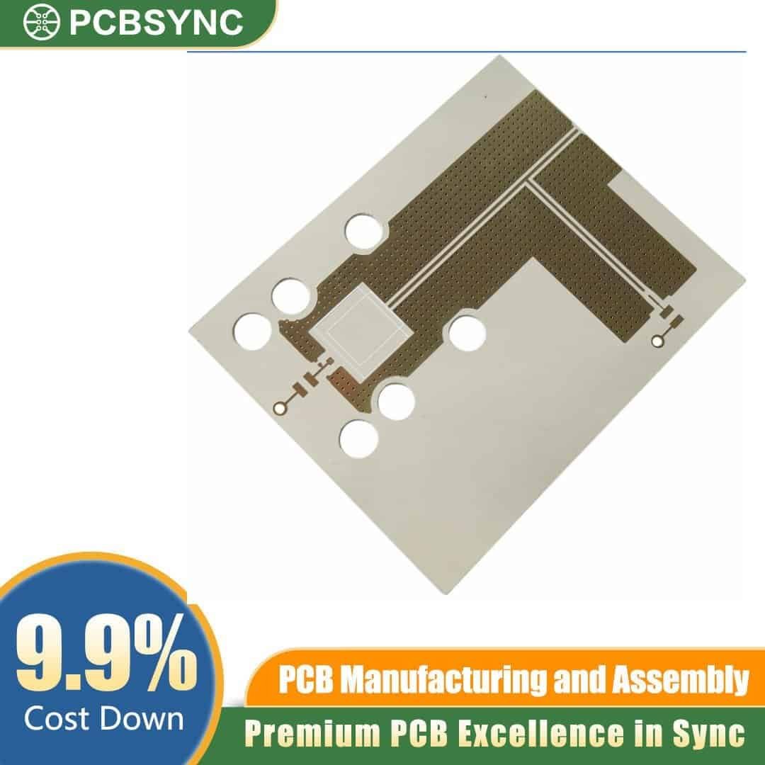
Engineered for the most demanding high-frequency applications, the PCBSync Rogers RT/duroid 5870 4-Layer RF Board delivers exceptional electrical performance where signal integrity cannot be compromised. Built on Rogers Corporation’s flagship PTFE-based laminate and finished to professional aerospace standards, this board is the trusted choice for engineers designing microwave, millimeter-wave, and high-speed digital systems.
Premium Materials, Precision Manufacturing
At the heart of this 4-layer stack-up sits Rogers RT/duroid 5870, a PTFE composite reinforced with randomly-oriented glass microfibers. With a remarkably low dielectric constant (Dk = 2.33) and an industry-leading dissipation factor (Df = 0.0012 at 10 GHz), this substrate minimizes signal loss across frequencies extending well into the Ka-band and beyond. Its uniform electrical properties, near-zero moisture absorption (<0.02%), and isotropic Dk make it ideal for tightly controlled impedance networks.
PCBSync builds each board to precise specifications:
- Substrate: Rogers RT/duroid 5870, 0.8mm (31 mil) total thickness
- Layer Count: 4 layers with controlled-impedance routing
- Copper Weight: 1/2 oz (17.5 µm) on outer and inner layers
- Surface Finish: ENIG (Electroless Nickel / Immersion Gold), 3 µ” gold over 120–240 µ” nickel
- Dielectric Constant (Dk): 2.33 ± 0.02
- Dissipation Factor (Df): 0.0012 @ 10 GHz
- Thermal Coefficient of Dk: −115 ppm/°C
- Operating Temperature: −55°C to +250°C
Why This Board Wins in RF Design
The combination of 1/2 oz copper and a 0.8mm PTFE substrate enables fine-line etching for 50-ohm microstrip and stripline structures, GCPW launches, and tightly-coupled differential pairs. The 3 µ” gold ENIG finish provides a flat, RoHS-compliant surface that excels for fine-pitch BGA assembly, wire bonding, and long-term solderability — all without the skin-effect penalties associated with HASL.
Four layers give you the routing real estate for complex RF front ends: a top signal layer for active components and transmission lines, dedicated ground planes for shielding and impedance reference, and an inner power or auxiliary signal layer. Every panel undergoes flying-probe or fixture electrical testing, AOI inspection, impedance verification, and IPC-A-600 Class 2/3 visual standards.
Engineered for Mission-Critical Applications
This board is purpose-built for:
- 5G mmWave base stations and small-cell radios
- Satellite communications and SATCOM payloads
- Phased-array and active antenna systems
- Automotive radar (24 GHz, 77 GHz, 79 GHz)
- Aerospace and defense radar platforms
- Test and measurement instrumentation
- Microwave point-to-point backhaul links
Order with Confidence from PCBSync
PCBSync combines Rogers-authorized material sourcing, mixed-dielectric stack-up expertise, and rigorous QC under ISO 9001 and AS9100. Lead times are clearly published, every file is reviewed by RF-experienced engineers, and a full impedance report ships with each order. Whether you’re prototyping a single radar module or scaling production for a 5G deployment, this Rogers 5870 4-layer RF PCB delivers the performance, repeatability, and traceability your project demands.
Upload your Gerbers today and quote your Rogers RT/duroid 5870 4-layer low-loss RF PCB in minutes.