Inquire: Call 0086-755-23203480, or reach out via the form below/your sales contact to discuss our design, manufacturing, and assembly capabilities.
Quote: Email your PCB files to Sales@pcbsync.com (Preferred for large files) or submit online. We will contact you promptly. Please ensure your email is correct.
Notes: For PCB fabrication, we require PCB design file in Gerber RS-274X format (most preferred), *.PCB/DDB (Protel, inform your program version) format or *.BRD (Eagle) format. For PCB assembly, we require PCB design file in above mentioned format, drilling file and BOM. Click to download BOM template To avoid file missing, please include all files into one folder and compress it into .zip or .rar format.
If you’ve ever worked on LED lighting projects or power electronics, you’ve probably encountered the thermal limitations of standard FR4 boards. I remember my first high-power LED driver project—the board was getting so hot you could barely touch it, and component failure rates were through the roof. That’s when I discovered aluminum PCBs, and honestly, they changed the game for thermal management in my designs.
This guide covers everything you need to know about aluminum PCBs—from the fundamental structure and material selection to real-world applications and design considerations. Whether you’re an experienced engineer looking for specific thermal conductivity data or someone exploring metal-core PCBs for the first time, you’ll find practical, actionable information here.
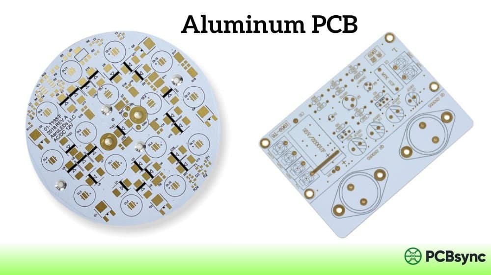
An aluminum PCB (also called aluminum base PCB, aluminum substrate PCB, or MCPCB—metal core PCB) is a type of printed circuit board that uses aluminum as its base material instead of the traditional FR4 fiberglass. The aluminum substrate acts as an efficient heat sink, rapidly transferring heat away from components and dissipating it into the surrounding environment.
The key difference from standard PCBs lies in thermal conductivity. While FR4 material has a thermal conductivity of around 0.3 W/mK, aluminum substrates typically range from 1.0 to 5.0 W/mK—that’s roughly 3 to 17 times more efficient at conducting heat. This makes aluminum PCBs the go-to choice for applications where thermal management is critical.
Most aluminum PCBs are single-sided, though double-sided and even multilayer versions exist. The manufacturing complexity increases significantly with additional layers, which is why single-layer aluminum boards dominate the market, particularly for LED applications.
Structure of Aluminum PCB
Understanding the layer structure is essential for selecting the right aluminum PCB for your application. Unlike standard FR4 boards, aluminum PCBs have a unique four-layer construction optimized for heat transfer.
Circuit Layer (Copper Foil)
The top layer is the copper circuit layer where your traces and component pads are etched. Aluminum PCBs typically use thicker copper than standard boards—ranging from 1oz to 10oz (35μm to 350μm). This thicker copper allows for higher current-carrying capacity, which is particularly important in power applications.
One design consideration: thicker copper requires wider trace spacing and larger minimum trace widths due to etching constraints. If you’re working with 3oz copper or above, you’ll need to apply width compensation during design to account for etching undercut.
Dielectric Layer (Insulation Layer)
This is the heart of any aluminum PCB—and where material selection really matters. The dielectric layer provides electrical insulation between the copper traces and the aluminum base while simultaneously transferring heat. Typical thickness ranges from 50μm to 200μm.
The dielectric is usually a polymer-ceramic composite. The polymer provides electrical isolation and bonding strength, while ceramic fillers enhance thermal conductivity. Higher thermal conductivity dielectrics (2.0+ W/mK) cost more but significantly improve heat dissipation performance.
When selecting dielectric materials, consider the trade-off: thinner dielectrics reduce thermal resistance but lower breakdown voltage. For high-voltage applications, you’ll need thicker dielectric layers even if it means slightly worse thermal performance.
Aluminum Base Layer
The aluminum base provides mechanical support and acts as the primary heat spreader. Common thickness ranges from 0.8mm to 3.0mm, with 1.0mm and 1.6mm being most popular. Thicker bases offer better heat spreading but add weight and cost.
Different aluminum alloys serve different purposes. Aluminum 5052 and 6061 are common choices, with 5052 offering better corrosion resistance and 6061 providing superior machinability. For most LED and power applications, standard aluminum alloys work perfectly fine.
Base Membrane (Optional)
Some aluminum PCBs include a protective membrane on the back of the aluminum base. This prevents scratches during handling and protects against unwanted oxidation. The membrane comes in two variants: standard (rated up to 120°C) and high-temperature (rated to 250°C). For most applications, the standard membrane works fine, but reflow soldering processes may require the high-temperature option.
Aluminum PCB Layer Structure Summary
Layer
Typical Thickness
Function
Copper Foil
35μm – 350μm (1oz-10oz)
Circuit traces, component mounting pads
Dielectric
50μm – 200μm
Electrical insulation + thermal transfer
Aluminum Base
0.8mm – 3.0mm
Heat spreading, mechanical support
Base Membrane
Optional
Surface protection, oxidation prevention
Types of Aluminum PCB
Aluminum PCBs come in several configurations, each suited to different applications and complexity levels.
Single-Layer Aluminum PCB
The most common type. One copper layer on an aluminum substrate. Perfect for LED modules, simple power supplies, and applications where all components can be placed on one side. Lower cost and faster turnaround times make single-layer boards the default choice for high-volume LED production.
Double-Layer Aluminum PCB
Two copper layers with the aluminum core in between. Uses plated through-holes (PTH) for layer-to-layer connections. More complex and expensive than single-layer, but allows for denser routing. The aluminum core sits between the layers, requiring careful via design—you need insulated vias that pass through the metal without shorting.
Multilayer Aluminum PCB
Three or more copper layers on an aluminum base. Rare and expensive due to manufacturing complexity. Used in high-density applications where thermal management and circuit complexity both matter—think advanced power modules or specialized military electronics.
Flexible Aluminum PCB
Uses thin aluminum and flexible dielectric materials (often polyimide-based) to create bendable circuits. These maintain thermal conductivity while allowing installation in curved enclosures. Common in automotive lighting where boards need to conform to headlight housings or tight spaces.
Hybrid Aluminum PCB
Combines FR4 and aluminum substrates in one board. The FR4 section handles complex signal routing while the aluminum portion manages heat from power components. A practical solution when you need both thermal management and multi-layer routing capability in a single design.
Benefits of Aluminum PCB
Superior Heat Dissipation
This is the primary reason engineers choose aluminum PCBs. The metal substrate conducts heat away from components 5-10 times more effectively than FR4. In LED applications, proper heat management can extend LED lifespan by 50% or more—when junction temperatures drop, LEDs last longer and maintain better color consistency.
From a practical standpoint, aluminum boards let you push higher power levels through smaller form factors. Where an FR4 design might require bulky external heatsinks, an aluminum PCB can often handle the thermal load directly.
Improved Dimensional Stability
Aluminum PCBs exhibit excellent dimensional stability across temperature ranges. When heated from 30°C to 150°C, dimensional change is typically only 2.5-3.0%. This stability reduces thermal stress on solder joints and components during temperature cycling, improving long-term reliability.
Mechanical Strength and Durability
The aluminum base provides significantly better mechanical strength than FR4 or ceramic substrates. This makes aluminum boards more resistant to physical stress, vibration, and accidental drops during manufacturing. For automotive and industrial applications subject to constant vibration, this durability is crucial.
Lightweight Construction
Despite the metal base, aluminum PCBs are surprisingly lightweight compared to boards with separate heatsinks. Aluminum’s density (2.7 g/cm³) is about one-third that of copper, making it ideal for weight-sensitive applications in aerospace, automotive, and portable electronics.
Environmental Considerations
Aluminum is non-toxic and highly recyclable. The material can be recovered and reused at end-of-life without degradation, aligning with RoHS requirements and sustainability initiatives. Many manufacturers now offer lead-free compatible aluminum PCB options.
Aluminum PCB vs. FR4 PCB: When to Choose Which
The decision between aluminum and FR4 ultimately comes down to thermal requirements, budget, and application complexity.
Aluminum PCB vs. FR4 Comparison
Parameter
Aluminum PCB
FR4 PCB
Thermal Conductivity
1.0 – 5.0 W/mK
0.25 – 0.35 W/mK
Layer Count
Typically 1-2 (up to 4)
1 to 20+ layers
Cost
Higher per board
Lower per board
Best Applications
LED, Power electronics, Automotive
Consumer electronics, Complex digital
Operating Temperature
Up to 150°C+ (material dependent)
Up to 130°C (standard)
Weight
Heavier but eliminates heatsink
Lighter alone, heavier with heatsink
Choose Aluminum PCB when: Your design has high heat-generating components, operates in high-temperature environments, requires compact form factor without external heatsinks, or involves LED lighting, power conversion, or automotive applications.
Choose FR4 when: Your circuit is complex with many layers, heat generation is minimal, cost is the primary driver, or you need standard PCB manufacturing with faster turnaround.
Aluminum PCB Material Brands and Selection
Material selection significantly impacts performance. Here’s a practical overview of major aluminum substrate brands and their typical specifications.
Ventec (tec-thermal Series)
Ventec offers one of the most comprehensive ranges of thermally conductive IMS (Insulated Metal Substrate) materials. Their VT-4A series is particularly popular for LED applications.
VT-4A2H: 2.2 W/mK thermal conductivity, Tg 105°C — good balance of performance and cost
Ventec materials are UL94 V-0 rated, halogen-free, and RoHS compliant. Their laminates are widely available through major PCB manufacturers worldwide.
Bergquist / TCLAD (Thermal Clad)
Bergquist Thermal Clad has been an industry standard for metal-core PCBs. Now part of TCLAD Inc., they continue to offer premium dielectric solutions.
HPL (High Power Lighting): Ultra-low thermal resistance, optimized for LED applications
HT (High Temperature): Resistant to thermal degradation, excellent dielectric breakdown
MP (Multi-Purpose): General-purpose with 2.4 W/mK thermal conductivity
Bergquist’s dielectric technology uses a proprietary polymer-ceramic blend that provides excellent electrical isolation at very thin layers (down to 76μm).
Shengyi
Shengyi is one of China’s largest CCL (copper-clad laminate) manufacturers, offering competitive pricing with solid performance.
SAR15: 1.5 W/mK, Tg 140°C — cost-effective general purpose
LED lighting is by far the largest application for aluminum PCBs. High-brightness LEDs generate significant heat at the junction, and excessive temperatures cause color shift, reduced efficiency, and shortened lifespan. Aluminum substrates efficiently transfer this heat away from the LED die, maintaining optimal operating temperatures.
Common LED applications include streetlights, commercial lighting, residential bulbs, automotive headlamps and taillights, display backlighting, and grow lights for horticulture. For high-power LED applications (1W+ per LED), aluminum PCBs are essentially mandatory for reliable long-term operation.
Power Electronics
Power converters, inverters, motor controllers, and switching power supplies all benefit from aluminum substrates. These devices handle high currents and generate substantial heat during operation. The combination of thick copper for current capacity and aluminum for heat spreading creates an optimal solution.
Specific applications include DC-DC converters, AC-DC power supplies, electric vehicle charging systems, solar inverters, UPS systems, and motor driver circuits. In these applications, maintaining low junction temperatures directly improves efficiency—power MOSFETs and IGBTs have higher on-resistance at elevated temperatures, creating a thermal runaway risk if heat isn’t properly managed.
Automotive Electronics
Modern vehicles contain numerous high-power electronic systems that demand excellent thermal management. Aluminum PCBs are used in headlight assemblies, tail light modules, dashboard illumination, battery management systems, ignition controllers, voltage regulators, and electronic power steering modules.
The automotive environment presents additional challenges: vibration resistance, wide temperature ranges, and long service life requirements. Aluminum’s mechanical stability and thermal performance address all these concerns.
Audio Equipment
Power amplifiers and audio output stages generate significant heat. Aluminum substrates help maintain stable operating temperatures, which is important for audio quality—thermal variations can cause drift in amplifier parameters. Professional audio equipment, car audio systems, and high-end consumer amplifiers commonly use aluminum PCBs.
Industrial and Medical Equipment
Industrial applications include motor controllers for manufacturing equipment, welding power supplies, and high-power laser drivers. Medical imaging equipment, surgical lighting systems, and diagnostic devices also rely on aluminum PCBs for reliable thermal management in critical applications.
Aluminum PCB Manufacturing Process
Understanding the manufacturing process helps engineers make better design decisions and set realistic expectations for lead times and costs.
Material Preparation
The process begins with aluminum base preparation. The aluminum sheet undergoes cleaning, chemical etching, and surface treatment to ensure proper adhesion of subsequent layers. Anodization or conversion coating may be applied to improve insulation and bonding properties. The prepared aluminum is then laminated with the dielectric layer and copper foil under high temperature and pressure.
Circuit Formation
Circuit patterning follows standard photolithographic processes: photoresist application, UV exposure through a photomask, development, and copper etching. For aluminum PCBs with thick copper (3oz+), etching parameters require careful control. The wider etch factor means you need to apply trace width compensation during design—typically 0.5-1.0 mil per side depending on copper thickness.
One manufacturing challenge unique to aluminum boards is solder mask printing. The height difference between thick copper traces and the base surface makes uniform mask application difficult. Many manufacturers use a two-pass solder mask process or resin filling followed by masking to achieve consistent coverage.
Mechanical Processing
Drilling, routing, and V-scoring on aluminum boards require specialized tooling. Carbide drill bits wear faster on metal substrates, and improper drilling parameters can create burrs that affect electrical performance. Professional manufacturers use specialized milling cutters and optimized feed rates to produce clean edges without metal debris.
For high-volume production, stamping or die-cutting may be more economical than routing for simple board outlines. However, complex shapes still require CNC routing for acceptable edge quality.
Aerospace and Defense
Extreme temperature environments, vibration, and reliability requirements make aluminum PCBs attractive for aerospace applications. Radar systems, avionics, satellite electronics, and military-grade power supplies benefit from the thermal stability and mechanical robustness. The weight advantage compared to traditional PCB-plus-heatsink combinations is particularly valuable in aircraft and spacecraft where every gram counts.
Telecommunications
Base station power amplifiers, 5G infrastructure equipment, and high-frequency RF modules require careful thermal management. Aluminum substrates help maintain stable operating temperatures for power transistors and RF components, ensuring consistent signal quality and long-term reliability in outdoor installations subject to weather extremes.
Design Tips for Aluminum PCB
Based on years of working with aluminum boards, here are practical design considerations that can save you time and avoid manufacturing issues.
Thermal Design Considerations
Place heat-generating components to maximize contact area with the aluminum substrate
Consider thermal vias under high-power components to improve heat transfer
Leave sufficient copper area around power devices for heat spreading
Calculate thermal resistance to ensure junction temperatures stay within spec
Manufacturing Considerations
Apply trace width compensation for copper weights above 3oz
Specify solder mask type—some standard masks don’t adhere well to thick copper
Use professional milling for outline to prevent burrs affecting electrical performance
For double-layer designs, ensure vias are properly insulated from the aluminum core
Material Selection Guidelines
Match dielectric thermal conductivity to your power requirements
Consider Tg requirements based on operating environment and soldering process
Verify material compatibility with your assembly process (lead-free vs. leaded solder)
Thermal Resistance Calculations
Estimating thermal performance before prototyping saves time and money. The total thermal resistance from junction to ambient consists of several components: junction-to-case (Rjc), case-to-board (Rcb), board thermal resistance (Rboard), and board-to-ambient (Rba).
For aluminum PCB thermal resistance: Rboard = t / (k × A), where t is dielectric thickness, k is thermal conductivity, and A is the heat spreading area. A typical 100μm dielectric with 2.0 W/mK conductivity and 1 cm² area gives Rboard = 0.0001 / (2.0 × 0.0001) = 0.5 °C/W. Compare this to FR4 at the same thickness: 0.0001 / (0.3 × 0.0001) = 3.3 °C/W.
This calculation shows why aluminum boards make such a difference—nearly 7× lower thermal resistance in this example. For a 5W LED, that’s the difference between 2.5°C and 16.5°C temperature rise through the board alone.
Assembly and Soldering Considerations
Aluminum boards require different reflow profiles due to their thermal mass
Preheat slowly to prevent thermal shock and component tombstoning
Peak temperatures may need extending due to heat absorption by aluminum
Hand soldering requires higher iron temperatures—the aluminum sinks heat rapidly
Consider selective soldering for mixed-technology boards with both SMT and through-hole
Storage and Handling
Aluminum PCBs are susceptible to moisture absorption and surface discoloration if improperly stored. Store boards in moisture-barrier bags with desiccant, in a cool, dry environment away from direct sunlight. The shelf life for properly stored laminates is typically 6-12 months for prepreg and 24 months for finished boards. Before assembly, bake moisture-sensitive boards according to IPC/JEDEC J-STD-033 guidelines to prevent delamination during reflow.
Useful Resources and Downloads
Here are some valuable resources for aluminum PCB design and material selection:
JEDEC (Joint Electron Device Engineering Council): jedec.org
Future Trends in Aluminum PCB Technology
The aluminum PCB market continues to evolve with new materials and manufacturing techniques. Higher thermal conductivity dielectrics (8+ W/mK) are emerging for extreme applications. Embedded component technology is being adapted for metal-core boards, allowing passives and even small ICs to be integrated within the PCB structure. Additionally, hybrid constructions combining aluminum with ceramic or graphite layers are pushing thermal performance boundaries further.
As electric vehicle production scales and LED efficiency demands increase, expect continued innovation in aluminum substrate technology. Understanding current capabilities positions you to take advantage of these advances as they become commercially available.
Frequently Asked Questions
What is the typical thermal conductivity range for aluminum PCBs?
Most aluminum PCB substrates offer thermal conductivity between 1.0 and 5.0 W/mK, depending on the dielectric material. Standard materials typically provide 1.0-2.0 W/mK, while premium materials can reach 3.0-5.0 W/mK or higher. For comparison, standard FR4 has thermal conductivity of only 0.25-0.35 W/mK.
Can aluminum PCBs be used for double-sided or multilayer designs?
Yes, though with limitations. Double-sided aluminum PCBs exist but require special via construction to pass through the metal core without shorting. Multilayer aluminum boards (3+ layers) are technically possible but expensive and uncommon. For complex routing requirements, consider hybrid designs that combine FR4 multilayer sections with aluminum thermal management zones.
How do I choose between aluminum and copper-based metal core PCBs?
Copper has about 60% higher thermal conductivity than aluminum (380 W/mK vs 200 W/mK for the base metal), making it better for extreme thermal demands. However, copper is heavier and significantly more expensive. For most LED and power applications, aluminum provides sufficient thermal performance at lower cost. Reserve copper-based substrates for applications where every degree of temperature reduction matters.
What surface finishes work best with aluminum PCBs?
Standard surface finishes work on aluminum PCBs, including HASL (hot air solder leveling), ENIG (electroless nickel immersion gold), OSP (organic solderability preservative), and immersion silver or tin. ENIG is popular for LED applications due to its flat surface and good reflectivity. For automotive applications, ENIG or selective gold plating provides reliable solderability and corrosion resistance.
What are the main disadvantages of aluminum PCBs?
The primary limitations include: higher cost per board compared to FR4; limited to single-layer or simple double-layer designs; thicker dielectrics needed for high voltage isolation can reduce thermal performance; and not flexible (standard aluminum boards are rigid). Additionally, manufacturing lead times may be longer than standard FR4, and not all PCB fabricators have aluminum PCB capabilities.
Conclusion
Aluminum PCBs have become essential for thermal management in LED lighting, power electronics, and automotive applications. The key to successful implementation lies in understanding the trade-offs: thermal conductivity vs. cost, dielectric thickness vs. breakdown voltage, and material selection vs. manufacturing complexity.
For most LED applications, a standard 1.5-2.0 W/mK aluminum substrate provides excellent performance at reasonable cost. Higher thermal conductivity materials (3.0+ W/mK) make sense for high-power applications where temperature margins are tight. Always work closely with your PCB manufacturer to optimize material selection, dielectric thickness, and design rules for your specific application.
As LED technology continues advancing toward higher power densities and as electric vehicle adoption accelerates, aluminum PCBs will only grow in importance. The market is expanding with new material options from established brands like Ventec, Bergquist, Totking, and Boyu, providing engineers more choices than ever for balancing performance and cost.
Whether you’re designing your first LED module or optimizing a high-volume production run, understanding aluminum PCB technology fundamentals will help you make better decisions and create more reliable products. The thermal management advantages, combined with mechanical durability and environmental benefits, make aluminum substrates an invaluable tool in any electronics engineer’s toolkit.
Inquire: Call 0086-755-23203480, or reach out via the form below/your sales contact to discuss our design, manufacturing, and assembly capabilities.
Quote: Email your PCB files to Sales@pcbsync.com (Preferred for large files) or submit online. We will contact you promptly. Please ensure your email is correct.
Notes: For PCB fabrication, we require PCB design file in Gerber RS-274X format (most preferred), *.PCB/DDB (Protel, inform your program version) format or *.BRD (Eagle) format. For PCB assembly, we require PCB design file in above mentioned format, drilling file and BOM. Click to download BOM template To avoid file missing, please include all files into one folder and compress it into .zip or .rar format.


