Inquire: Call 0086-755-23203480, or reach out via the form below/your sales contact to discuss our design, manufacturing, and assembly capabilities.
Quote: Email your PCB files to Sales@pcbsync.com (Preferred for large files) or submit online. We will contact you promptly. Please ensure your email is correct.
Notes: For PCB fabrication, we require PCB design file in Gerber RS-274X format (most preferred), *.PCB/DDB (Protel, inform your program version) format or *.BRD (Eagle) format. For PCB assembly, we require PCB design file in above mentioned format, drilling file and BOM. Click to download BOM template To avoid file missing, please include all files into one folder and compress it into .zip or .rar format.
A practical engineering guide covering the wire harness assembly process from design to production, quality standards, and industry applications.
What Is Wire Harness Assembly?
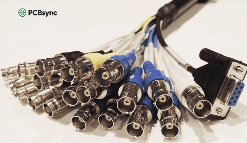
Wire harness assembly refers to the process of bundling multiple electrical wires, cables, and connectors into a single, organized unit that transmits power and signals within electronic systems. Think of it as the nervous system of any electrical device—from the dashboard of your car to the control panel of an industrial robot.
As a PCB engineer who’s worked on dozens of harness integration projects, I can tell you that a well-designed wire harness doesn’t just organize cables. It simplifies installation, reduces assembly errors, protects wires from environmental damage, and makes troubleshooting significantly easier down the line.
Unlike loose wiring, a wire harness binds conductors together using cable ties, tape, conduit, or braided sleeving. The harness is built on an assembly board (also called a pin board or form board) that acts as a full-scale template of the final product.
The design phase produces several critical documents:
Document
Purpose
Wiring Schematic
Shows electrical connections and component relationships
Harness Drawing
Full-scale layout with dimensions, routing, and callouts
Bill of Materials (BOM)
Complete list of wires, connectors, terminals, and accessories
Assembly Instructions
Step-by-step manufacturing guidelines
Step 2: Prototyping
Before committing to production, manufacturers build prototypes to:
Verify fit and form within the target equipment
Test electrical continuity and insulation resistance
Identify potential manufacturing issues
Validate the design against specifications
From my experience, skipping the prototype phase is a recipe for expensive rework. Even a “simple” 20-wire harness can have routing issues that only become apparent during physical assembly.
Step 3: Material Preparation
Wire Cutting
Automated cutting machines (like Komax or Schleuniger equipment) cut wires to precise lengths based on the BOM. Accuracy here is critical—even a few millimeters difference can cause problems during routing.
Wire Stripping
Machines strip insulation from wire ends to expose the conductor. Strip length must match terminal specifications exactly. Too short, and you get weak connections. Too long, and you risk short circuits.
Terminal Crimping
Terminals are attached to stripped wire ends using:
Automated crimp machines for high-volume production
Handheld crimping tools for prototypes and low-volume runs
Bench-top applicators for medium volumes
Critical Crimping Parameters:
Parameter
What to Check
Crimp Height
Must match manufacturer specifications (measured with micrometer)
Pull Force
Wire should not pull out under specified tension
Insulation Support
Crimp wings must fully wrap insulation without damage
Conductor Visibility
Wire strands visible in inspection window
Step 4: Assembly on Form Board
The form board (assembly board) is a full-scale template of the harness layout. Operators:
Place wires according to the routing diagram
Insert terminals into connector housings
Apply protective sleeving or conduit
Secure with cable ties, tape, or lacing cord
Attach identification labels
Why Manual Assembly Still Dominates:
Despite advances in automation, wire harness assembly remains approximately 80% manual labor. The reasons are practical:
High product customization requirements
Complex 3D routing that robots struggle with
Frequent design changes
Cost of automated tooling for low-to-medium volumes
Step 5: Electrical Testing
Every wire harness undergoes rigorous testing before shipment:
Test Type
What It Checks
Continuity Test
Verifies all connections are complete
Hi-Pot (Dielectric) Test
Confirms insulation integrity under high voltage
Insulation Resistance
Measures resistance between conductors
Functional Test
Simulates actual operating conditions
Step 6: Quality Inspection and Packaging
Final inspection includes:
Visual inspection against workmanship standards
Dimensional verification
Label verification
Documentation review
IPC/WHMA-A-620: The Industry Quality Standard
If you’re serious about wire harness assembly, you need to understand IPC/WHMA-A-620. This is the globally recognized standard for cable and wire harness acceptance criteria.
The Three Product Classes
Class
Description
Typical Applications
Class 1
General electronic products
Consumer electronics, toys, basic appliances
Class 2
Dedicated service products
Industrial equipment, telecom, business machines
Class 3
High-performance products
Medical devices, aerospace, military, life support
What IPC/WHMA-A-620 Covers
Wire preparation and strand damage limits
Crimping requirements and inspection criteria
Soldering workmanship
Connector and terminal installation
Harness securing and protection
Marking and labeling
Testing requirements
Pro Tip: When specifying harness requirements to a supplier, always include the IPC class. It eliminates ambiguity and ensures everyone works to the same quality level.
Common Wire Harness Components
Conductors
Wire Type
Typical Use
Key Properties
PVC Insulated
General purpose, indoor
Low cost, flexible, temperature limited
Cross-linked Polyethylene (XLPE)
Automotive, industrial
Heat resistant, flame retardant
Teflon (PTFE)
High-temperature, aerospace
Extreme temperature range, chemical resistant
Silicone
Medical, food processing
Biocompatible, flexible at low temps
Connectors and Terminals
Ring terminals – Secure bolt-down connections
Spade terminals – Quick-disconnect, easy service access
Pin and socket connectors – Multi-circuit, polarized mating
Sealed connectors – Weatherproof for automotive/outdoor use
Protective Materials
Material
Protection Against
Common Applications
PVC Tubing
Abrasion, bundling
General industrial
Braided Sleeving
Abrasion, heat
Automotive engine compartments
Heat Shrink
Moisture, strain relief
Connector transitions, splices
Spiral Wrap
Abrasion, flexibility
Robotic arms, moving applications
Conduit
Crushing, chemicals
Factory floor routing
Wire Harness Assembly Applications by Industry
Automotive
The average modern vehicle contains 40+ pounds of wiring—more than 1,500 individual wires. Wire harnesses connect everything from engine sensors to infotainment systems.
Aerospace
Aircraft harnesses must meet stringent weight, fire resistance, and reliability requirements. A commercial jet contains over 100 miles of wiring.
Medical Devices
Patient safety demands exceptional reliability. Class 3 workmanship and biocompatible materials are standard requirements.
Industrial Automation
Robotic systems and factory equipment rely on harnesses that withstand constant motion, vibration, and contamination.
Consumer Electronics
High-volume production of appliances, computers, and entertainment equipment drives demand for cost-effective harness solutions.
Design Best Practices for Wire Harness Assembly
1. Plan for Serviceability
Design harnesses with maintenance access in mind. Use connectors at logical service points—nobody wants to splice wires in the field.
2. Respect Bend Radius
Minimum bend radius is typically 4-10 times the cable diameter. Exceeding this stresses conductors and insulation, leading to premature failure.
3. Avoid Heat Sources
Route harnesses away from exhaust manifolds, power resistors, and other heat-generating components. Use thermal barriers when proximity is unavoidable.
4. Consider EMI/RFI
For signal integrity, separate power and signal wires. Use shielded cables and proper grounding for sensitive circuits.
5. Standardize Where Possible
Using common components across product lines reduces inventory costs and simplifies training.
Useful Resources and Downloads
Industry Standards:
IPC/WHMA-A-620 (Requirements and Acceptance for Cable and Wire Harness Assemblies) – shop.ipc.org
What is the difference between a wire harness and a wiring loom?
The terms are often used interchangeably. “Wiring loom” is more common in British English and European markets, while “wire harness” is the preferred term in North American manufacturing. Functionally, they describe the same product.
How long does it take to manufacture a custom wire harness?
Timeline varies significantly based on complexity:
Complexity
Prototype Lead Time
Production Lead Time
Simple (under 20 wires)
1-2 weeks
2-3 weeks
Medium (20-100 wires)
2-4 weeks
3-5 weeks
Complex (100+ wires)
4-8 weeks
6-10 weeks
Custom tooling, specialized materials, or certification requirements can extend these timelines.
Can wire harness assembly be fully automated?
Not entirely. While cutting, stripping, crimping, and testing can be automated, the actual routing and bundling process remains predominantly manual. The high degree of customization and three-dimensional complexity makes full automation impractical for most applications.
What certifications should I look for in a wire harness supplier?
At minimum, look for:
IPC/WHMA-A-620 certified personnel
ISO 9001 quality management
Industry-specific certifications (IATF 16949 for automotive, AS9100 for aerospace, ISO 13485 for medical)
How do I specify a wire harness for a new product?
Provide your supplier with:
Electrical schematic showing all connections
Mechanical envelope drawings with routing constraints
A good supplier will work with you to optimize the design for manufacturability.
Conclusion
Wire harness assembly is a specialized discipline that combines electrical engineering, mechanical design, and precision manufacturing. Whether you’re designing harnesses for consumer products or mission-critical aerospace systems, understanding the fundamentals covered in this guide will help you specify better products and work more effectively with manufacturing partners.
The key takeaways:
Design thoroughly before production—prototyping saves money long-term
Specify the appropriate IPC class for your application
Choose materials matched to your environmental requirements
Partner with certified manufacturers who understand your industry
For more technical guidance on related topics, explore our guides on cable harness assembly, cable assembly manufacturing, and wire harnessing techniques.
Inquire: Call 0086-755-23203480, or reach out via the form below/your sales contact to discuss our design, manufacturing, and assembly capabilities.
Quote: Email your PCB files to Sales@pcbsync.com (Preferred for large files) or submit online. We will contact you promptly. Please ensure your email is correct.
Notes: For PCB fabrication, we require PCB design file in Gerber RS-274X format (most preferred), *.PCB/DDB (Protel, inform your program version) format or *.BRD (Eagle) format. For PCB assembly, we require PCB design file in above mentioned format, drilling file and BOM. Click to download BOM template To avoid file missing, please include all files into one folder and compress it into .zip or .rar format.


