Inquire: Call 0086-755-23203480, or reach out via the form below/your sales contact to discuss our design, manufacturing, and assembly capabilities.
Quote: Email your PCB files to Sales@pcbsync.com (Preferred for large files) or submit online. We will contact you promptly. Please ensure your email is correct.
Notes: For PCB fabrication, we require PCB design file in Gerber RS-274X format (most preferred), *.PCB/DDB (Protel, inform your program version) format or *.BRD (Eagle) format. For PCB assembly, we require PCB design file in above mentioned format, drilling file and BOM. Click to download BOM template To avoid file missing, please include all files into one folder and compress it into .zip or .rar format.
After spending fifteen years designing PCBs for everything from medical devices to industrial control systems, I’ve lost count of how many times engineers have asked me: “Should I use through-hole assembly or SMT?” The answer is never simple—and anyone who tells you otherwise probably hasn’t dealt with a board that failed in the field because they chose the wrong PCB assembly method.
Through-hole assembly might seem like yesterday’s technology when over 90% of modern electronics use surface mount components. But here’s what the spec sheets don’t tell you: through-hole technology still dominates in aerospace, military, and power electronics—industries where reliability isn’t negotiable. The real question isn’t which technology is “better.” It’s which one fits your specific application.
This guide breaks down both assembly methods from a practical engineering perspective. I’ll cover the technical differences, cost considerations, and real-world scenarios where each technology excels. By the end, you’ll have a clear framework for making this critical design decision.
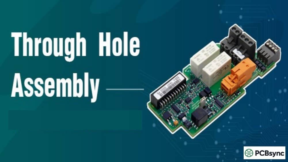
Through-hole assembly (THA) involves mounting electronic components by inserting their leads through drilled holes in a printed circuit board. The leads are then soldered to pads on the opposite side, creating both an electrical connection and a strong mechanical bond.
Before SMT emerged in the 1980s, through-hole technology was the only game in town. Every component—from resistors to integrated circuits—went through the board. The process hasn’t changed much since then: drill holes, insert components, solder. What has changed is our understanding of when this “old-school” approach still makes sense.
Types of Through-Hole Components
Through-hole components come in two primary configurations:
Axial leads: Wire leads extend from both ends of the component body (like standard resistors). These provide excellent heat dissipation and are easy to hand-solder.
Radial leads: Both leads exit from the same side of the component (like electrolytic capacitors). This configuration saves board space compared to axial packages.
Through-Hole Soldering Methods
Modern through-hole assembly uses three primary soldering techniques:
Wave soldering: The PCB passes over a wave of molten solder that fills all holes simultaneously. Ideal for high-volume production with consistent through-hole layouts.
Selective soldering: A programmable solder fountain targets specific through-hole joints without affecting nearby SMT components. Essential for mixed-technology boards.
Hand soldering: Manual soldering using a soldering iron. Best for prototypes, repairs, and low-volume production where setup costs outweigh labor.
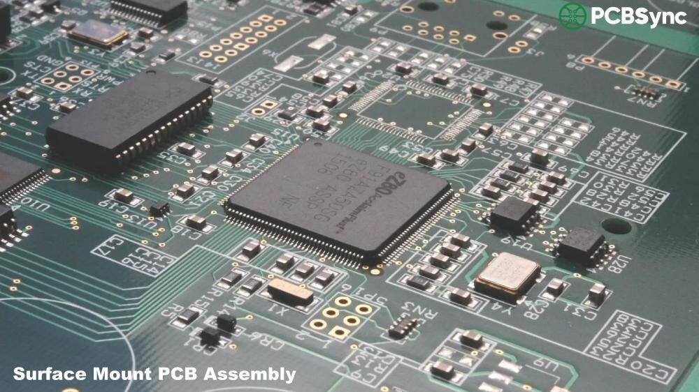
Understanding Surface Mount Technology
Surface mount technology (SMT) places components directly onto PCB surface pads without requiring drilled holes. Instead of leads passing through the board, small metal contacts on the component’s underside connect to corresponding pads through solder paste that’s melted in a reflow oven.
The SMT process is highly automated: a stencil applies solder paste to pad locations, pick-and-place machines position components at thousands of placements per hour, and reflow ovens create consistent solder joints across the entire board simultaneously. This automation explains why SMT dominates modern electronics manufacturing.
Through-Hole Assembly vs. SMT: Key Differences
The fundamental difference comes down to how components attach to the PCB. Through-hole leads pass completely through the board, creating a robust mechanical anchor. SMT components sit on the surface, held only by solder joints. This single distinction drives most of the tradeoffs between the two technologies.
Table 1: Through-Hole Assembly vs. SMT Comparison
Factor
Through-Hole Assembly
SMT
Mechanical Strength
Excellent—leads anchor through board
Moderate—surface solder joints only
Component Density
Low—holes consume routing area
High—both sides usable
Heat Tolerance
Superior—better thermal dissipation
Limited—direct surface attachment
Assembly Speed
Slow—<1,000 placements/hour
Fast—10,000+ placements/hour
Per-Unit Cost (Volume)
Higher—drilling + manual labor
Lower—automation scales efficiently
Rework/Repair
Easy—accessible joints
Difficult—tiny components, specialized tools
High-Frequency Performance
Limited—longer leads add inductance
Excellent—shorter signal paths
When to Use Through-Hole Assembly
Through-hole assembly remains the right choice for specific applications where its advantages outweigh the size and cost penalties. Here’s when you should seriously consider through-hole technology:
High-Reliability and Harsh Environments
Military and aerospace applications demand through-hole assembly because components face extreme accelerations, vibrations, thermal cycling, and mechanical shock. When a fighter jet pulls 9Gs or a satellite endures launch vibrations, solder joints need the mechanical strength that only through-hole connections provide. I’ve seen SMT components literally shake off boards that through-hole versions survived without issue.
Power Electronics and High-Current Applications
Transformers, large electrolytic capacitors, power MOSFETs, and high-current connectors typically require through-hole mounting. These components generate significant heat and handle substantial current—conditions where through-hole’s superior thermal dissipation and robust connections become critical. The leads themselves act as heat sinks, transferring thermal energy into the PCB’s copper layers.
Prototyping and Development
During early product development, designs change frequently. Through-hole components are easier to swap, test, and modify by hand. You can desolder a through-hole DIP package with a basic soldering iron; replacing a 0.4mm pitch BGA requires expensive rework equipment. For proof-of-concept work, the assembly method that lets you iterate fastest often wins.
Connectors and Mechanical Interfaces
USB ports, D-sub connectors, terminal blocks, and other components that users physically interact with should almost always use through-hole mounting. Every cable insertion and removal stresses the solder joints. Through-hole connections can withstand forces up to 10 times greater than equivalent SMT joints—a critical margin when users plug and unplug cables thousands of times over a product’s lifetime.
When to Use Surface Mount Technology
For the majority of modern electronics, SMT delivers the right combination of size, cost, and performance. Here are the scenarios where surface mount technology clearly wins:
High-Volume Production
Once you’re manufacturing thousands of units, SMT’s automation advantage becomes overwhelming. Pick-and-place machines can place 25,000+ components per hour with sub-millimeter accuracy. The same board assembled with through-hole technology might take 10-20 times longer. At scale, that time difference translates directly to cost savings that can make or break product margins.
Compact and Portable Devices
Smartphones, wearables, IoT sensors, and medical implants simply can’t exist with through-hole technology. SMT components can be 60-80% smaller than through-hole equivalents, and you can place them on both sides of the board. When your entire product needs to fit in a space smaller than a through-hole resistor, the choice is obvious.
High-Speed Digital and RF Applications
At frequencies above 100MHz, through-hole leads become antennas. Their parasitic inductance and capacitance distort signals and create noise. SMT components, with their minimal lead length, maintain signal integrity at frequencies where through-hole designs would fail. Any modern high-speed digital design—DDR memory, USB 3.0, PCIe—relies on SMT for this reason.
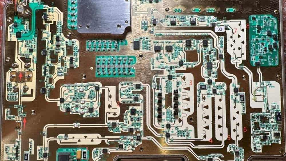
Most real-world PCBs don’t choose one technology exclusively—they use both. A typical industrial control board might use SMT for microcontrollers, memory, and signal conditioning while using through-hole assembly for power connectors, terminal blocks, and high-power components. This hybrid approach captures the benefits of each technology where they matter most.
The key to successful mixed-technology design is planning your assembly sequence. SMT components typically go through reflow first, then through-hole parts are added via wave or selective soldering. This sequence matters because through-hole components often can’t survive reflow temperatures, and SMT joints would be disturbed by wave soldering without proper protection.
Table 2: Quick Application Guide
Application
Recommended Method
Key Reason
Aerospace/Military
Through-Hole
Vibration/shock resistance
Consumer Electronics
SMT
Size, cost, volume
Power Supplies
Through-Hole + SMT
High-current paths + control logic
Industrial Controls
Through-Hole + SMT
Connectors + processing
Wearables/IoT
SMT
Miniaturization critical
Prototyping
Through-Hole
Easy modification/testing
IPC Standards for Assembly Quality
Regardless of which assembly method you choose, your boards should comply with relevant IPC standards. These industry specifications define acceptable workmanship, inspection criteria, and quality levels:
IPC-A-610: Acceptability of Electronic Assemblies. The most widely used standard for inspecting assembled PCBs.
IPC-J-STD-001: Requirements for Soldered Electrical and Electronic Assemblies. Covers materials, methods, and acceptance criteria for soldering.
IPC-7251: Generic Requirements for Through-Hole Design and Land Pattern Standard. Specific guidelines for through-hole assembly footprints.
IPC-6012: Qualification and Performance Specification for Rigid Printed Boards. Defines Class 1, 2, and 3 quality levels.
For through-hole assembly, pay particular attention to barrel fill requirements: Class 2 products require 50% minimum fill, while Class 3 (aerospace/military) demands 75% fill. These specifications directly impact reliability under thermal cycling and mechanical stress.
Useful Resources and References
For deeper dives into PCB assembly technology, these resources provide valuable technical information:
No. While SMT dominates modern electronics (over 90% of assemblies), through-hole assembly remains essential for specific applications. Military, aerospace, power electronics, and industrial equipment still rely heavily on through-hole technology for its superior mechanical reliability. The technology continues to evolve with selective soldering improvements and isn’t going away anytime soon.
Which is cheaper: through-hole or SMT?
SMT is significantly cheaper at production volumes because of automation. However, for very small runs (under 50 units), through-hole can be more economical since it doesn’t require solder stencils or pick-and-place programming. The crossover point depends on board complexity, but generally SMT wins on cost for any volume production.
Can I mix through-hole and SMT on the same board?
Absolutely—most boards do exactly this. The standard approach is to reflow SMT components first, then add through-hole parts via wave soldering or selective soldering. Just ensure adequate clearance between SMT components and through-hole pads (typically 3mm minimum) to prevent interference during the secondary soldering process.
What IPC class should I specify for through-hole assembly?
Class 2 covers most commercial and industrial applications with adequate reliability. Class 3 is required for aerospace, military, and medical life-support equipment—it specifies tighter tolerances like 75% minimum barrel fill (vs. 50% for Class 2). Don’t over-specify: Class 3 significantly increases cost without benefit for general-purpose electronics.
How do I choose between wave soldering and selective soldering?
Wave soldering is faster and cheaper for boards with only through-hole components on the bottom side. Selective soldering is necessary when you have SMT components on both sides or when through-hole components are near SMT parts that could be damaged by wave exposure. Most mixed-technology boards today use selective soldering because it offers precise control without expensive pallets or fixtures.
Making the Right Choice
Through-hole assembly and SMT aren’t competing technologies—they’re complementary tools for different engineering challenges. The best PCB designs leverage each method where it performs best: SMT for density, speed, and cost; through-hole assembly for reliability, power handling, and mechanical integrity.
Before finalizing your assembly approach, ask yourself: What’s the production volume? What environmental stresses will the board face? Which components absolutely require through-hole mounting? The answers will guide you toward the right balance of technologies for your specific application.
Remember that your assembly house is a valuable partner in this decision. Experienced contract manufacturers have seen thousands of designs and can offer practical guidance on what works—and what doesn’t—for your particular requirements. Don’t hesitate to involve them early in the design process.
Inquire: Call 0086-755-23203480, or reach out via the form below/your sales contact to discuss our design, manufacturing, and assembly capabilities.
Quote: Email your PCB files to Sales@pcbsync.com (Preferred for large files) or submit online. We will contact you promptly. Please ensure your email is correct.
Notes: For PCB fabrication, we require PCB design file in Gerber RS-274X format (most preferred), *.PCB/DDB (Protel, inform your program version) format or *.BRD (Eagle) format. For PCB assembly, we require PCB design file in above mentioned format, drilling file and BOM. Click to download BOM template To avoid file missing, please include all files into one folder and compress it into .zip or .rar format.


