Inquire: Call 0086-755-23203480, or reach out via the form below/your sales contact to discuss our design, manufacturing, and assembly capabilities.
Quote: Email your PCB files to Sales@pcbsync.com (Preferred for large files) or submit online. We will contact you promptly. Please ensure your email is correct.
Notes: For PCB fabrication, we require PCB design file in Gerber RS-274X format (most preferred), *.PCB/DDB (Protel, inform your program version) format or *.BRD (Eagle) format. For PCB assembly, we require PCB design file in above mentioned format, drilling file and BOM. Click to download BOM template To avoid file missing, please include all files into one folder and compress it into .zip or .rar format.
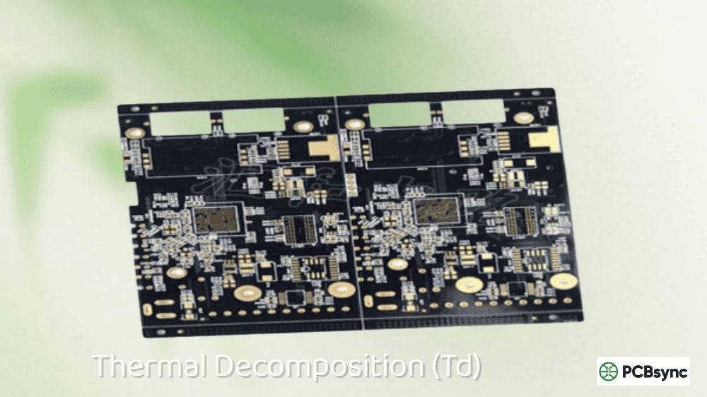
If you’ve spent any time working with PCB materials, you’ve probably encountered the term “Thermal Decomposition” or “Td” on a datasheet. But what does it actually mean for your design and manufacturing process? As someone who has dealt with countless delamination issues and material failures over the years, I can tell you that understanding Td is absolutely crucial for building reliable circuit boards, especially in today’s lead-free soldering environment.
Thermal Decomposition (Td) represents one of the most critical thermal parameters in PCB laminate selection, yet it’s often overlooked in favor of the more commonly discussed Glass Transition Temperature (Tg). This comprehensive guide will walk you through everything you need to know about Td, from its fundamental definition to practical applications in your design workflow.
Thermal Decomposition Temperature, commonly abbreviated as Td, is the temperature at which a PCB laminate material begins to chemically decompose. According to IPC-TM-650 Method 2.4.24.6, Td is defined as the temperature at which the material loses at least 5% of its original mass weight. Unlike the Glass Transition Temperature (Tg), which represents a reversible physical change, thermal decomposition is an irreversible chemical process that permanently damages the material.
When a PCB substrate reaches its Td, the polymer chains in the resin system begin to break down. This breakdown releases volatile compounds and causes the material to lose structural integrity. The result? Your board starts falling apart at a molecular level, and there’s no going back.
How Thermal Decomposition (Td) is Measured
The industry-standard method for measuring Td is Thermogravimetric Analysis (TGA), as specified in IPC-TM-650 Method 2.4.24.6. Here’s how the process works:
A sample of the laminate material (typically 10-30 mg) is prepared by removing all copper cladding
The sample is placed in a TGA instrument and its initial mass is recorded at room temperature (not exceeding 50°C)
The sample is heated at a controlled rate of 10°C per minute from ambient temperature to 550°C under nitrogen atmosphere
The instrument continuously monitors the sample’s mass throughout the heating process
Two key temperatures are recorded: Td (2%) when 2% mass loss occurs, and Td (5%) when 5% mass loss occurs
The Td (5%) value is the commonly reported specification on material datasheets. Some manufacturers also report Td (2%), which provides an earlier warning threshold for the onset of decomposition.
Thermal Decomposition (Td) vs Glass Transition Temperature (Tg)
One of the most common points of confusion in PCB material selection is understanding the difference between Td and Tg. While both are critical thermal parameters, they represent fundamentally different phenomena:
Parameter
Tg (Glass Transition)
Td (Decomposition)
Type of Change
Physical (phase transition)
Chemical (decomposition)
Reversibility
Reversible
Irreversible
Typical Range
130°C – 280°C
300°C – 400°C+
What Happens
Material softens, CTE increases dramatically
Polymer chains break, material loses mass and integrity
Test Method
DSC or TMA
TGA (IPC-TM-650 2.4.24.6)
Primary Concern
Dimensional stability, CTE mismatch
Material degradation, delamination
The key takeaway here is that Tg represents a transition point where material properties change temporarily, while Td represents a point of no return. Your design should operate well below Tg for normal use, and your manufacturing processes should stay well below Td to prevent permanent damage.
Why Thermal Decomposition (Td) Matters for Your PCB Design
Understanding Td is critical for several reasons that directly impact your product’s reliability and manufacturing success:
Lead-Free Soldering Requirements
The shift to lead-free soldering has made Td more important than ever. Traditional tin-lead solder melts at around 183°C, with typical reflow peak temperatures of 210-245°C. Lead-free solders (like SAC305) require peak temperatures of 240-270°C, putting significantly more thermal stress on your PCB materials.
Here’s the problem: conventional FR-4 materials often have Td values around 300-310°C. While this sounds like adequate margin, studies have shown that materials begin losing resin mass well before reaching the 5% threshold. At lead-free soldering temperatures, standard FR-4 can lose 1.5-3% of its resin content, which can cause delamination, void formation, and long-term reliability issues.
Multiple Reflow and Rework Cycles
Modern PCB assembly rarely involves just a single pass through the reflow oven. Consider a typical double-sided SMT assembly with through-hole components:
First reflow cycle for top-side SMT components
Second reflow cycle for bottom-side SMT components
Wave soldering for through-hole components
Potential rework operations for defective joints
Each thermal cycle brings the material closer to its decomposition threshold. This cumulative thermal damage is why materials with higher Td values (340°C+) are often specified for complex assemblies. Research indicates that materials with Td around 300°C frequently experience problems with lead-free soldering, while materials with Td of 400°C typically perform without issues.
Delamination Prevention
Delamination is one of the most common failure modes in PCB manufacturing, and Td plays a significant role. As the PCB approaches its decomposition temperature during soldering, the resin begins to break down and release volatile gases. This creates internal pressure between layers, which can cause separation at the weakest interfaces.
The reflow oven temperatures of 240-250°C required for lead-free solder can generate enough internal pressure to separate layers when combined with trapped moisture. This is why pre-baking boards before assembly and selecting appropriate Td materials is essential for preventing delamination.
Td Values for Common PCB Materials
Not all PCB materials are created equal when it comes to thermal decomposition resistance. Here’s a comparison of common materials and their typical Td values:
Important Note: Interestingly, a higher Tg doesn’t always mean a higher Td. Some low-end FR-4 materials with Tg of 140°C may actually have higher Td values than certain high-Tg (170°C) versions. Always check both specifications when selecting materials.
How to Select PCB Materials Based on Thermal Decomposition (Td)
Selecting the right material involves considering several factors beyond just the Td value itself. Here’s my recommended approach:
Assess Your Assembly Process
Identify your soldering method: Lead-free reflow requires higher Td materials than traditional tin-lead processes.
Count thermal cycles: More reflow passes and rework potential means you need higher Td margins.
Consider peak temperatures: Your Td should be at least 50-60°C above your maximum process temperature.
Evaluate Operating Conditions
High ambient temperature applications (automotive, industrial) need higher Td margins
Power electronics with high heat dissipation require careful thermal analysis
Products with long service life need extra reliability margin
Balance Cost vs Performance
Higher Td materials typically cost more and may require modified fabrication parameters. High-Tg substrates are generally more rigid and brittle, which can affect drilling efficiency and increase drill bit wear. Find the sweet spot that meets your reliability requirements without unnecessarily inflating costs.
What Happens When You Exceed Thermal Decomposition Temperature
Exceeding the Td threshold, even briefly, can cause several serious problems:
Delamination and Layer Separation
As the resin decomposes, volatile compounds are released creating internal pressure. This pressure can force layers apart, especially at interfaces between different materials (copper-to-laminate, prepreg-to-core). Delamination can occur between surface layers (visible as blistering) or internally (detectable only through cross-sectioning or acoustic microscopy).
Degraded Signal Integrity
The loss of resin material changes the dielectric constant and impedance of controlled impedance traces. For high-speed designs, even small changes in dielectric properties can cause signal integrity issues, including impedance discontinuities, increased crosstalk, and higher insertion loss.
Structural and Mechanical Weakness
Decomposition weakens the bond between glass fibers and resin matrix, reducing overall mechanical strength. This makes the board more susceptible to warping, cracking, and handling damage. In severe cases, the board may become too fragile to survive automated assembly equipment.
Outgassing and Contamination
Volatile compounds released during decomposition can contaminate solder joints and component surfaces. This is particularly problematic for fine-pitch components and ball grid arrays (BGAs), where outgassing products can prevent proper solder wetting or create voids in solder joints.
Best Practices for Managing Thermal Decomposition (Td) in PCB Design
Based on years of experience and industry best practices, here are my top recommendations for managing Td in your pcb designs:
Material Selection Guidelines
For lead-free assembly, specify materials with Td ≥340°C minimum
For high-reliability applications (automotive, aerospace, medical), target Td ≥360°C
Always consider Td alongside Tg, CTE, and moisture absorption for a complete picture
Request material certificates that include both Td (2%) and Td (5%) values
Manufacturing Process Control
Pre-bake boards before assembly to remove absorbed moisture (typically 4-6 hours at 105-125°C)
Optimize reflow profiles to minimize time above liquid temperature
Control peak temperatures within ±5°C of target
Monitor and document thermal profiles for each board design
Design Considerations
Distribute heat-generating components to avoid thermal hotspots
Use thermal vias to help conduct heat away from sensitive areas
Consider the cumulative effect of multiple reflow cycles in your design margin
For thick boards or high layer counts, increase Td margin to account for longer heat-up times
Testing and Quality Control for Thermal Decomposition
Several test methods can help verify that your PCB materials and processes are compatible with your thermal requirements:
Test Method
IPC Standard
Purpose
TGA
IPC-TM-650 2.4.24.6
Determine decomposition temperature (Td)
T260/T288
IPC-TM-650 2.4.24.1
Time to delamination at 260°C or 288°C
Thermal Stress
IPC-TM-650 2.6.8
Solder float testing for PTH reliability
Reflow Simulation
IPC-TM-650 2.6.27
Convection reflow assembly simulation
DSC
IPC-TM-650 2.4.25
Glass transition temperature and cure factor
Useful Resources and Reference Materials
Here are some valuable resources for further research on thermal decomposition and PCB materials:
Industry Standards and Specifications
IPC-TM-650 Test Methods Manual – Available at electronics.org/test-methods
IPC-4101E – Specification for Base Materials for Rigid and Multilayer Printed Boards
IEC 61189-2-807 – Decomposition Temperature (Td) using TGA
Material Databases and Manufacturer Resources
IPC Shop (shop.ipc.org) – Purchase official IPC standards
Isola Laminate Materials – Detailed datasheets with Td values
Rogers Corporation – High-frequency material specifications
Panasonic Electronic Materials – Megtron series datasheets
DuPont (Kapton) – Polyimide material data
Technical Documentation
Sierra Circuits Blog – PCB substrate and material guides
Altium Resources – IPC slash sheet explanations
I-Connect007 – Industry news and technical articles
Frequently Asked Questions About Thermal Decomposition (Td)
1. What is a good Td value for lead-free PCB assembly?
For lead-free assembly with peak reflow temperatures of 240-270°C, you should select materials with Td values of at least 340°C. For high-reliability applications or boards requiring multiple reflow cycles, target Td values of 360°C or higher. Materials with Td around 300°C have been shown to experience problems during lead-free soldering, while materials at 400°C typically perform without issues.
2. Can I use standard FR-4 for lead-free soldering?
Standard FR-4 (Tg 130-140°C) with Td around 300-310°C can technically survive lead-free reflow, but it’s not recommended for production use. The margin is too thin, and you risk delamination, especially with multiple thermal cycles. For lead-free assembly, always specify high-Tg FR-4 (Tg 170°C+, Td 340°C+) or better materials. The small additional cost is insignificant compared to the reliability improvement.
3. How does moisture affect thermal decomposition?
Moisture trapped in the PCB laminate can significantly increase the risk of delamination during thermal exposure. When the board is heated above 100°C, absorbed moisture turns to steam and creates internal pressure. This pressure, combined with weakened resin bonds as the temperature approaches Td, can cause catastrophic layer separation. Always pre-bake boards that have been stored in humid conditions (4-6 hours at 105-125°C) before assembly.
4. What’s the relationship between Tg and Td?
Tg and Td are independent material properties, though they’re both determined by the resin chemistry. A higher Tg doesn’t automatically mean a higher Td. Some materials achieve high Tg through additives that actually lower Td. Conversely, some standard Tg materials have excellent Td performance. Always check both specifications and consider them together with CTE when selecting materials for your application.
5. How many reflow cycles can my PCB survive?
The number of safe reflow cycles depends on your material’s Td, T260/T288 values, and the actual thermal profile used. Industry guidelines suggest that materials with T260 of 60 minutes and T288 greater than 10 minutes can withstand at least 12 solder cycles without delamination. However, each cycle uses some of the material’s thermal budget, and cumulative damage builds up. For safety, design your process to minimize thermal cycles and always maintain proper moisture control.
Conclusion
Thermal Decomposition (Td) is a critical parameter that every PCB engineer and designer needs to understand. With the widespread adoption of lead-free soldering and increasing demands for reliability in automotive, aerospace, and industrial applications, selecting materials with appropriate Td values has never been more important.
The key points to remember are: Td represents an irreversible chemical breakdown of the material, unlike Tg which is a reversible physical transition. For lead-free assembly, always specify materials with Td of 340°C or higher. Consider the cumulative effect of multiple thermal cycles on your material. And always evaluate Td alongside Tg, CTE, and moisture absorption for a complete thermal reliability picture.
By following the guidelines and best practices outlined in this article, you’ll be well-equipped to select appropriate materials and design robust manufacturing processes that avoid thermal decomposition-related failures. Your boards will thank you, and so will your customers.
Inquire: Call 0086-755-23203480, or reach out via the form below/your sales contact to discuss our design, manufacturing, and assembly capabilities.
Quote: Email your PCB files to Sales@pcbsync.com (Preferred for large files) or submit online. We will contact you promptly. Please ensure your email is correct.
Notes: For PCB fabrication, we require PCB design file in Gerber RS-274X format (most preferred), *.PCB/DDB (Protel, inform your program version) format or *.BRD (Eagle) format. For PCB assembly, we require PCB design file in above mentioned format, drilling file and BOM. Click to download BOM template To avoid file missing, please include all files into one folder and compress it into .zip or .rar format.


