Inquire: Call 0086-755-23203480, or reach out via the form below/your sales contact to discuss our design, manufacturing, and assembly capabilities.
Quote: Email your PCB files to Sales@pcbsync.com (Preferred for large files) or submit online. We will contact you promptly. Please ensure your email is correct.
Notes: For PCB fabrication, we require PCB design file in Gerber RS-274X format (most preferred), *.PCB/DDB (Protel, inform your program version) format or *.BRD (Eagle) format. For PCB assembly, we require PCB design file in above mentioned format, drilling file and BOM. Click to download BOM template To avoid file missing, please include all files into one folder and compress it into .zip or .rar format.
After spending over a decade in PCB manufacturing and SMT assembly, I can tell you that thermal cycling testing is one of those quality assurance processes that separates reliable electronics from field failures waiting to happen. If you’ve ever had a board fail in an automotive application or watched a consumer device brick after six months, chances are thermal stress played a role.
This guide covers everything you need to know about thermal cycling testing—from the physics behind it to the IPC and JEDEC standards that govern it. Whether you’re a design engineer trying to improve your board’s reliability or a quality manager setting up test protocols, this article will give you actionable insights you can apply immediately.
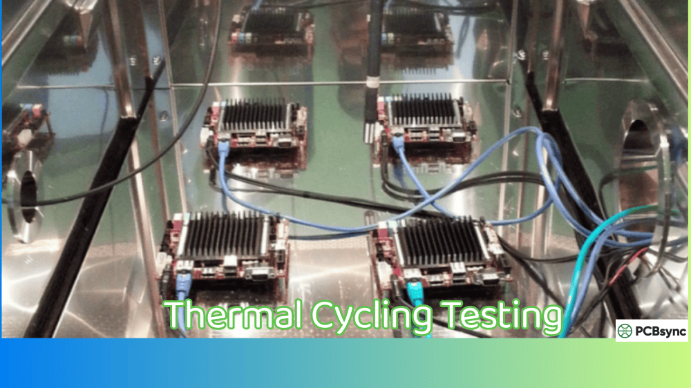
Thermal cycling testing is an accelerated reliability test that subjects PCBs and electronic assemblies to repeated temperature fluctuations between high and low extremes. The goal is straightforward: compress years of real-world thermal stress into days or weeks of controlled testing.
During normal operation, electronic devices heat up when powered on and cool down when switched off. This happens thousands of times over a product’s lifetime. Each cycle creates mechanical stress due to the thermal expansion and contraction of different materials with mismatched Coefficients of Thermal Expansion (CTE).
When I run thermal cycling tests, I’m essentially asking the board: “Will your solder joints survive five years in the field?” The answer comes in the form of resistance measurements, visual inspections, and failure analysis data that tell a complete reliability story.
How Thermal Cycling Testing Differs from Thermal Shock Testing
Many engineers confuse these two tests, but they serve different purposes:
Parameter
Thermal Cycling Testing
Thermal Shock Testing
Temperature transition rate
Slow (10-20°C/min)
Rapid (>30°C/min)
Typical temperature range
-40°C to +125°C
-55°C to +150°C
Dwell time at extremes
10-15 minutes
5-10 minutes
Test medium
Air chamber
Liquid bath or dual chamber
Primary failure mode
Solder joint fatigue
Delamination, via cracking
Realism
Simulates field conditions
Extreme stress screening
Thermal cycling is generally more representative of actual field conditions because electronic devices rarely experience instantaneous temperature changes. However, thermal shock testing can quickly identify latent defects and material weaknesses that might take longer to appear under gentler cycling conditions.
Why Thermal Cycling Testing Matters for PCB Manufacturing
The CTE Mismatch Problem
Here’s the fundamental challenge every PCB designer faces: the materials in an electronic assembly expand at different rates when heated.
Material
CTE (ppm/°C)
Silicon die
2.6-3.0
Copper
17
FR-4 substrate (X-Y plane)
14-18
FR-4 substrate (Z-axis)
60-70
SAC305 solder
21-23
Ceramic (Al₂O₃)
6-7
BGA molding compound
15-20
When you heat an assembly with these materials, everything expands—but not equally. The solder joint connecting a silicon die (CTE ~3) to an FR-4 board (CTE ~15) experiences significant shear stress. Repeat this stress a few thousand times, and you’ll see crack initiation and propagation in the solder joint.
Economic Impact of Thermal-Related Field Failures
Field failures cost anywhere from 10x to 100x more than catching the same defect during manufacturing. A thermal cycling test setup costs between $50,000 and $200,000, but a single product recall can cost millions in warranty claims, brand damage, and lost customers.
Industries with high thermal reliability requirements include:
Automotive: Engine compartment temperatures can swing from -40°C in winter starts to +150°C during operation
Aerospace: Altitude changes create rapid temperature gradients
Industrial: Factory equipment may operate 24/7 with regular power cycling
Medical devices: Sterilization cycles and operating room temperature variations
Telecommunications: Outdoor equipment faces daily temperature swings
Common Failure Modes Revealed by Thermal Cycling Testing
Solder Joint Fatigue
This is the most common failure mode I see in thermal cycling tests. Solder joints, particularly in BGA packages, develop micro-cracks that propagate with each cycle. The cracks typically start at stress concentration points—usually the corners of the solder ball where CTE mismatch is greatest.
Lead-free SAC305 solder joints behave differently than traditional tin-lead joints. Research shows SAC305 joints can fail after 1,500 cycles between -40°C and +125°C due to fatigue. The recrystallization of tin grains in the high-strain regions accelerates crack growth.
Via and PTH Cracking
Plated-through holes (PTHs) and vias are vulnerable to thermal cycling because the copper plating must accommodate Z-axis expansion of the FR-4 substrate. High-aspect-ratio vias (those with depth-to-diameter ratios above 8:1) are particularly susceptible. According to IPC reliability data, failure rates increase by approximately 20% in rapid temperature transitions.
PCB Delamination
When temperatures exceed the glass transition temperature (Tg) of the laminate material, the substrate becomes more susceptible to separation between layers. Low-Tg substrates (below 130°C) exposed to temperatures above 150°C often show delamination. This is why high-reliability applications typically specify high-Tg laminates (170°C or higher).
Intermetallic Compound Growth
At elevated temperatures, intermetallic compounds (IMCs) continue to grow at the solder-copper interface. Excessive IMC thickness makes solder joints brittle and prone to fracture. Thermal cycling accelerates this growth, making it visible in test samples much faster than in field conditions.
Key Industry Standards for Thermal Cycling Testing
IPC-9701B: Surface Mount Solder Attachment Characterization
IPC-9701B is the go-to standard for thermal cycling characterization of SMT solder joints. Released as an update to IPC-9701A (which addressed lead-free assemblies), this specification provides:
Test vehicle design requirements
Temperature profile parameters
Failure criteria based on electrical resistance measurements
Weibull analysis methodology for characteristic life calculations
A typical IPC-9701 compliant test might cycle between 0°C and 100°C with 10-minute dwells at each extreme, running for 1,000 to 6,000 cycles depending on the application class.
JEDEC JESD22-A104: Temperature Cycling Standard
JEDEC’s standard is widely used for semiconductor package qualification. It defines multiple test conditions:
Condition
Temperature Range
Typical Application
TC-A
-55°C to +85°C
Commercial/Consumer
TC-B
-55°C to +125°C
Industrial
TC-C
-65°C to +150°C
Automotive/Aerospace
TC-G
-40°C to +125°C
Automotive AEC-Q100
TC-H
-55°C to +150°C
Military/High-Rel
The standard specifies transition rates not exceeding 15°C per minute and minimum dwell times of 10 minutes at each temperature extreme.
IPC-TM-650 Method 2.6.27: Thermal Stress Testing
This test method evaluates the thermal cycling resistance of PCB interconnects by subjecting test coupons to multiple reflow profiles. The pass criteria require that resistance not increase by more than 5% after six thermal excursions to peak temperatures of 230°C or 260°C.
MIL-STD-883 Method 1010: Military Standard
For defense and aerospace applications, MIL-STD-883 defines severe thermal cycling conditions:
Temperature range: -65°C to +150°C
Minimum dwell: 10 minutes
Maximum transfer time: 1 minute
Typically requires 100-1,000 cycles
Thermal Cycling Test Methods and Equipment
Air-to-Air Thermal Cycling
This is the most common method used in reliability labs. A programmable environmental chamber alternates between hot and cold air streams to bring test assemblies to temperature. Modern chambers achieve ramp rates of 5-15°C per minute with temperature uniformity of ±2°C across the working zone.
Pros:
Representative of actual field conditions
Gentle enough to avoid artificial failure modes
Cost-effective for high-volume testing
Cons:
Slower than liquid-to-liquid methods
Tests can run for weeks or months
Highly Accelerated Thermal Shock (HATS)
HATS testing uses a single chamber with rapid air temperature transitions to stress test vehicles much faster than conventional cycling. A test that would take 6 weeks in a standard chamber can be completed in about 1 week using HATS methods.
Interconnect Stress Testing (IST)
IST represents a different approach—instead of using air to change temperature, an electrical current heats the test coupon from within. This method stresses vias directly and can complete equivalent testing in hours rather than days. The daisy-chained vias are monitored for resistance changes that indicate developing cracks.
Liquid-to-Liquid Thermal Shock
For the most aggressive testing, liquid-to-liquid shock chambers transfer test samples between hot and cold fluid baths. This achieves effective transition rates exceeding 50°C per second. While not representative of field conditions, it rapidly identifies weak designs and material incompatibilities.
Best Practices for Thermal Cycling Testing
Test Vehicle Design
Proper test vehicle design is critical for meaningful results. Based on my experience, here’s what matters:
Use daisy-chain packages: These allow continuous electrical monitoring during cycling. When a solder joint cracks, you’ll see a resistance increase immediately.
Include multiple component types: BGAs, QFNs, chip resistors, and connectors fail at different rates. Test them all to understand your weakest link.
Match the actual PCB stackup: Use the same laminate material, copper weights, and surface finish as your production boards. A test result on ENIG finish doesn’t apply to OSP.
Include test coupons: IPC-2221 compliant daisy-chain coupons allow via reliability testing without destroying actual assemblies.
Pre-conditioning Requirements
Before thermal cycling begins, assemblies should undergo preconditioning to simulate assembly stress:
3X reflow: Simulates standard SMT assembly
6X reflow: Simulates assembly plus rework scenarios
IPC-9701 recommends comparing “as received” coupons against preconditioned samples. The delta between these groups indicates how much margin your design has for manufacturing variability.
Monitoring and Failure Detection
Continuous in-situ resistance monitoring is the gold standard for thermal cycling tests. A failure is typically defined as:
20% increase in resistance (IPC-9701 criterion)
Resistance exceeding 1000Ω for more than 200 nanoseconds
Any open circuit condition
Modern event detectors can capture intermittent failures that would be missed by post-cycle measurements. This is particularly important for solder joints that may only show failure at temperature extremes.
Statistical Analysis with Weibull Distribution
Single sample results mean nothing—you need statistical analysis to make reliability predictions. Weibull analysis is the standard approach:
Characteristic life (η): The number of cycles at which 63.2% of samples fail
B10 life: Cycles to 10% failure rate—often the specification limit
For meaningful Weibull analysis, plan for at least 20-30 samples per test condition. Insufficient sample sizes produce wide confidence intervals that make prediction unreliable.
Design Tips for Improved Thermal Cycling Reliability
Solder Joint Optimization
Use larger pads where possible: Bigger solder joint area distributes stress
Avoid high-stress corner positions: Place critical components away from board corners where warpage is maximum
Consider underfill for BGAs: Underfill dramatically improves thermal cycling life by reducing solder joint strain
Material Selection
High-Tg laminates: Choose Tg ≥170°C for applications with thermal cycling above 125°C
Low-CTE substrates: Consider polyimide or ceramic for extreme temperature applications
SAC305 alternatives: Newer alloys with antimony, bismuth, or indium additions show improved thermal fatigue resistance
Via Design Rules
Minimize aspect ratio: Keep depth-to-diameter ratio below 8:1 for standard FR-4
Use filled and capped vias: Prevents solder wicking and improves thermal reliability
How many thermal cycles are required for qualification?
It depends on your application class and end-use environment. Consumer electronics typically require 500-1,000 cycles. Automotive applications per AEC-Q100 require 1,000-3,000 cycles depending on Grade (0-3). Military and aerospace specifications often require demonstration of 1,000+ cycles with zero failures.
What temperature range should I use for thermal cycling testing?
Select ranges that bracket your expected field conditions with margin. For consumer products, -20°C to +85°C is common. Automotive under-hood applications typically test -40°C to +125°C. The wider the temperature swing, the more accelerated the test. IPC-9701 provides acceleration factors for converting test cycles to equivalent field life.
How do I correlate thermal cycling test results to field life?
Use acceleration factor models like Norris-Landzberg or Engelmaier equations. These relate test cycles to field cycles based on temperature range, dwell time, and cycling frequency. For example, 1,000 cycles at -40°C to +125°C might correlate to 5-10 years of field life for a consumer product cycling once per day.
Should I use thermal cycling or thermal shock testing?
Use thermal cycling when you want realistic reliability prediction. Use thermal shock when you need rapid screening or want to stress designs beyond normal conditions. Many qualification programs require both—thermal cycling for solder joint fatigue characterization and thermal shock for screening out material defects.
What failure analysis should I perform on failed samples?
Standard failure analysis includes cross-sectioning and optical microscopy to identify crack location and propagation path, dye penetration testing for crack mapping, X-ray inspection for void identification, and SEM/EDS analysis for intermetallic evaluation. Document failure modes carefully—they provide design feedback for the next revision.
Setting Up Your Thermal Cycling Test Program
Equipment Selection Considerations
When setting up a thermal cycling capability in-house, consider these factors:
Chamber Size and Capacity: Match chamber size to your test vehicle dimensions with room for air circulation. A chamber that’s too small creates hot and cold spots. Most reliability labs use chambers with 2-8 cubic feet of working volume.
Temperature Range and Ramp Rate: For general PCB testing, a chamber capable of -70°C to +180°C covers most requirements. Ensure the chamber can achieve at least 10°C/minute ramp rates under load—spec sheet numbers are often for empty chambers.
Control System Accuracy: Look for temperature control within ±1°C and uniformity of ±2°C across the working zone. Modern controllers should support programmable profiles with multiple ramp and dwell segments.
Data Acquisition Integration: Your chamber should interface with resistance monitoring equipment. Event detection systems that can flag intermittent failures during temperature transitions are essential for catching early-stage solder joint fatigue.
Cost-Benefit Analysis of In-House vs. Outsourced Testing
Factor
In-House Testing
Contract Lab Testing
Initial investment
$80,000-$250,000
None
Per-test cost
Low (utilities only)
$5,000-$15,000/test
Lead time
Immediate
2-6 weeks queue time
Flexibility
High
Limited to standard protocols
Technical expertise
Must develop internally
Available on demand
Maintenance burden
Ongoing costs
Included in service
For companies running more than 10-15 thermal cycling tests annually, in-house capability typically pays for itself within 3-5 years. Smaller volumes or occasional testing are better served by contract laboratories.
Calibration and Maintenance Requirements
Thermal cycling chambers require regular calibration to maintain accuracy:
Temperature sensor calibration: Quarterly or after any sensor replacement
Control system verification: Semi-annual check against reference thermocouples
Chamber uniformity mapping: Annual verification with multi-point temperature survey
Compressor maintenance: Follow manufacturer schedules for refrigerant systems
Door seal inspection: Monthly visual check; replace at first sign of deterioration
Document all calibration activities—your test results are only as valid as your equipment certification.
Real-World Case Studies
Case Study 1: Automotive ECU Solder Joint Failures
A Tier-1 automotive supplier experienced field returns of engine control units (ECUs) after 18-24 months in service. Failure analysis revealed cracked BGA solder joints on the main processor. Thermal cycling testing during development had shown the design meeting requirements, so what went wrong?
Investigation discovered that field conditions were more severe than the original test profile. The ECU was mounted closer to the exhaust manifold than originally specified, experiencing temperature swings from -40°C to +145°C rather than the tested +125°C maximum.
Solution: The team redesigned the BGA mounting with an underfill process and qualified the assembly using TC-H conditions (-55°C to +150°C). The underfilled design survived 3,000+ cycles versus 800 cycles for the original design.
Case Study 2: Consumer Electronics Via Failures
A smartphone manufacturer saw display connection failures appearing after software updates. The updates increased processor utilization, raising internal temperatures by 8-10°C. Although the display connector’s solder joints were fine, vias in the flex-to-PCB interconnect were cracking.
The root cause was high-aspect-ratio vias (10:1) in a thin, dense HDI stackup. Accelerated thermal cycling confirmed via barrel cracking after just 200 cycles at -40°C to +85°C.
Solution: Redesign reduced via aspect ratio to 6:1 by increasing via diameter. The modified design passed 1,500 cycles with no failures. The lesson: don’t assume via reliability—test it explicitly.
Useful Resources and Standards Downloads
Resource
Description
Link
IPC-9701B
Thermal cycling test method for SMT solder attachments
Conclusion: Making Thermal Cycling Testing Work for You
Thermal cycling testing isn’t just a box to check for qualification—it’s a tool for understanding and improving your product’s reliability. The test data you collect drives better designs, identifies manufacturing issues before they reach customers, and provides the confidence needed for long-term warranty commitments.
Start with the right standards for your application, design test vehicles that represent your actual products, collect enough samples for statistical significance, and analyze failures thoroughly. The investment in proper thermal cycling testing pays dividends in reduced field failures and satisfied customers.
If there’s one thing I’ve learned in this industry, it’s that thermal stress will find weaknesses in your design. Better to find them in the lab than in the field.
Inquire: Call 0086-755-23203480, or reach out via the form below/your sales contact to discuss our design, manufacturing, and assembly capabilities.
Quote: Email your PCB files to Sales@pcbsync.com (Preferred for large files) or submit online. We will contact you promptly. Please ensure your email is correct.
Notes: For PCB fabrication, we require PCB design file in Gerber RS-274X format (most preferred), *.PCB/DDB (Protel, inform your program version) format or *.BRD (Eagle) format. For PCB assembly, we require PCB design file in above mentioned format, drilling file and BOM. Click to download BOM template To avoid file missing, please include all files into one folder and compress it into .zip or .rar format.


