Inquire: Call 0086-755-23203480, or reach out via the form below/your sales contact to discuss our design, manufacturing, and assembly capabilities.
Quote: Email your PCB files to Sales@pcbsync.com (Preferred for large files) or submit online. We will contact you promptly. Please ensure your email is correct.
Notes: For PCB fabrication, we require PCB design file in Gerber RS-274X format (most preferred), *.PCB/DDB (Protel, inform your program version) format or *.BRD (Eagle) format. For PCB assembly, we require PCB design file in above mentioned format, drilling file and BOM. Click to download BOM template To avoid file missing, please include all files into one folder and compress it into .zip or .rar format.
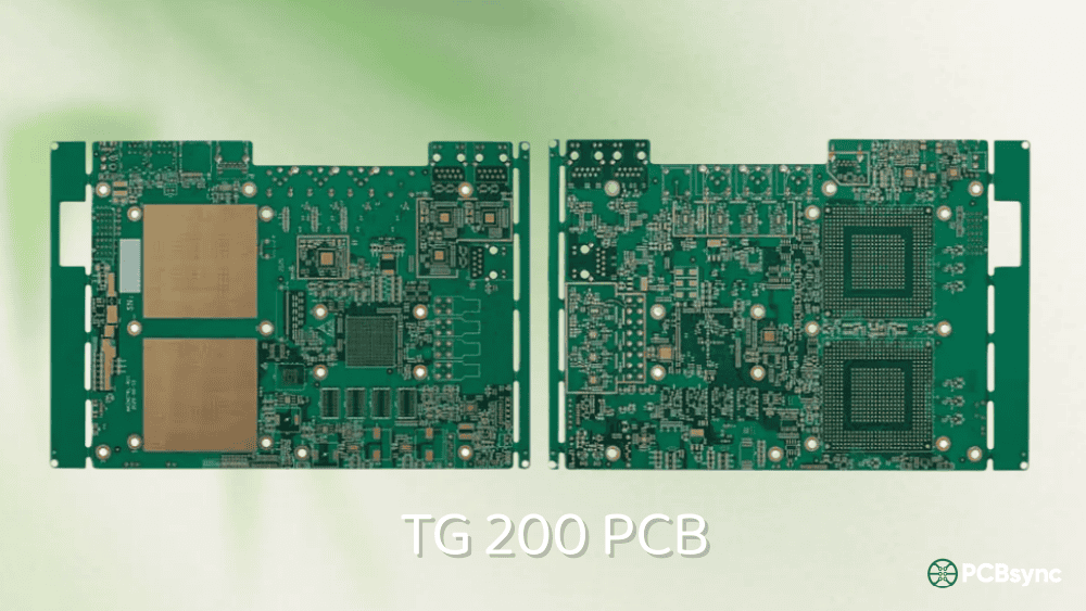
There’s a sweet spot in high-temperature PCB materials that many engineers overlook. When standard high-Tg FR4 (170-180°C) falls short of your thermal requirements but polyimide feels like overkill for the application and budget, Tg 200 PCB materials occupy that crucial middle ground. These ultra-high-Tg substrates deliver exceptional thermal performance while maintaining the processability and cost advantages of FR4-based systems.
After specifying materials for everything from downhole oil and gas electronics to high-speed data center switches, I’ve found that knowing when to reach for Tg 200 PCB material — rather than defaulting to Tg 180 or jumping straight to polyimide — can save significant cost while meeting demanding thermal requirements. This guide explains where Tg 200 fits in the material hierarchy, which specific products deliver this performance, and how to decide if it’s right for your application.
What is Tg 200 PCB? Defining the Ultra-High-Tg Tier
The Tg 200 PCB designation refers to circuit board materials with a glass transition temperature of 200°C or higher while still maintaining characteristics of FR4-type processing. At this temperature threshold, the resin system begins transitioning from rigid to pliable, but these advanced materials resist this change far longer than standard high-Tg alternatives.
This 200°C threshold represents a significant jump from the commonly specified Tg 180 materials. It’s achieved through specialized resin chemistries — including BT (Bismaleimide Triazine) epoxy systems, advanced multifunctional epoxies, and hybrid formulations — that provide denser molecular cross-linking and superior thermal stability.
The Ultra-High-Tg Advantage
What makes Tg 200 PCB materials special isn’t just the higher temperature rating. These materials typically deliver a combination of benefits:
Extended Operating Temperature: Following the 25-30°C safety margin below Tg, Tg 200 materials support continuous operation at 170-175°C — approximately 20°C higher than Tg 180 alternatives.
Superior Thermal Cycling Endurance: The advanced resin systems maintain mechanical integrity through more thermal cycles, critical for applications with repeated heating and cooling.
Often Combined with Low-Loss Properties: Many Tg 200 materials (like Panasonic MEGTRON 7) are designed for high-speed digital applications, offering both thermal stability AND excellent signal integrity — a dual benefit that premium applications increasingly require.
Better Moisture Resistance: Ultra-high-Tg formulations typically exhibit lower moisture absorption rates, improving long-term reliability in humid environments.
Tg 200 PCB Position in the Material Hierarchy
Understanding where Tg 200 PCB fits helps you make informed material selection decisions. Here’s how the complete FR4 and specialty material spectrum breaks down:
Classification
Tg Range
Material Category
Typical Applications
Relative Cost
Standard Tg
130-140°C
Basic FR4
Consumer electronics
1.0x
Medium Tg
150-165°C
Enhanced FR4
Industrial, automotive interior
1.05-1.10x
High Tg
170-175°C
High-Tg FR4
Under-hood, telecom, multilayer
1.15-1.25x
Premium High Tg
180-185°C
Premium FR4
Aerospace, military, extreme
1.25-1.40x
Ultra-High Tg
200-210°C
Advanced FR4/BT Epoxy
Extreme thermal, high-speed
1.40-1.80x
Specialty
250°C+
Polyimide
Flex, extreme temperature
2.0-3.0x
Ceramic/PTFE
280°C+
Specialty
RF/Microwave, extreme
2.5-4.0x
The Tg 200 PCB tier occupies a strategic position: it delivers thermal performance approaching polyimide while maintaining FR4-style processing, better dimensional stability, and significantly lower cost than true specialty materials.
Why the 200°C Threshold Matters
The jump from 180°C to 200°C isn’t just incremental — it opens doors to applications that were previously polyimide-only territory:
Oil and Gas Downhole Electronics: Wellbore temperatures can reach 175-200°C. Tg 200 materials provide adequate margin without polyimide cost.
Power Electronics Under Extreme Load: High-current inverters and converters generate substantial heat during peak operation.
Automotive Powertrain Adjacent: Electronics mounted near (but not on) engine blocks experience sustained elevated temperatures.
High-Layer Sequential Lamination: Boards requiring 4-5+ lamination cycles benefit from Tg 200’s superior thermal stability through repeated processing.
Tg 200 PCB vs Tg 180 vs Polyimide: Critical Comparison
This three-way comparison addresses the key decision most engineers face when specifying ultra-high-temperature materials.
Head-to-Head Specification Comparison
Property
Tg 180 FR4
Tg 200 FR4/BT
Polyimide
Glass Transition (Tg)
180-185°C
200-210°C
250-260°C
Decomposition Temp (Td)
350-360°C
380-410°C
400-450°C
Max Operating Temp
~155°C
~175°C
~230°C
Z-axis CTE (below Tg)
40-50 ppm/°C
35-45 ppm/°C
50-60 ppm/°C
Total Z-expansion
2.0-2.5%
1.5-2.2%
2.5-3.5%
Dk @ 1GHz
4.0-4.3
3.4-4.0
3.2-3.5
Df @ 1GHz
0.018-0.022
0.002-0.015
0.008-0.015
Moisture Absorption
≤0.08%
≤0.05%
0.2-0.4%
Flexibility
Rigid
Rigid
Flexible option
Processing
Standard
Standard/Modified
Specialized
Relative Cost
1.0x baseline
1.3-1.5x
2.0-2.5x
Key Observations from the Comparison
Thermal Performance: Tg 200 materials bridge the gap effectively — they provide 20°C more operating margin than Tg 180 while costing 40-60% less than polyimide.
Electrical Properties: Many Tg 200 materials (especially MEGTRON series) offer superior Dk/Df characteristics even compared to polyimide, making them excellent for high-speed digital applications.
Moisture Performance: Tg 200 materials typically exhibit lower moisture absorption than both Tg 180 FR4 and polyimide — an often-overlooked advantage for humid environments.
Z-axis Expansion: Some Tg 200 formulations achieve lower total Z-expansion than polyimide, improving via reliability in thick multilayer stackups.
When Tg 180 is Sufficient
Standard premium high-Tg material remains appropriate when:
Operating temperatures stay below 150°C sustained
Standard lead-free assembly (1-2 reflow cycles)
Layer counts up to 20 layers with standard sequential lamination
First choice: Isola IS410 (established qualification)
Alternative: Verify specific program requirements
Ultra-High Temperature Applications for Tg 200 PCB
The Tg 200 PCB excels in environments where Tg 180 falls short but polyimide is unnecessary or cost-prohibitive.
Oil and Gas Downhole Electronics
Wellbore electronics face some of the harshest thermal environments in any industry:
Depth Category
Typical Temperature
Material Recommendation
Shallow (<3,000m)
100-130°C
Tg 170-180 sufficient
Medium (3,000-5,000m)
130-160°C
Tg 180-200 recommended
Deep (5,000-7,000m)
160-185°C
Tg 200 required
Ultra-deep (>7,000m)
185-220°C
Polyimide necessary
Measurement-while-drilling (MWD), logging-while-drilling (LWD), and downhole sensors increasingly use Tg 200 PCB materials to reduce costs compared to polyimide while meeting demanding thermal requirements.
High-Speed Data Center and Networking
Modern data centers push signal speeds to 112G PAM4 and beyond, requiring materials that deliver both thermal stability and signal integrity:
Switch/Router Line Cards: High port density generates significant heat while demanding ultra-low-loss signal paths. MEGTRON 7’s combination of Tg 200°C and Df 0.0015 makes it ideal.
Optical Transceiver PCBs: DSP-based coherent optics operate at elevated temperatures while requiring pristine high-speed channels.
AI/ML Accelerator Boards: GPU and TPU boards generate substantial heat during training workloads, requiring thermal headroom beyond standard materials.
Power Electronics
High-current power conversion generates substantial heat:
EV Inverters: Silicon carbide (SiC) switching enables higher operating temperatures
Industrial Motor Drives: Continuous operation under heavy load
Renewable Energy Inverters: Solar and wind inverters in exposed locations
Data Center Power: Server power supplies with high power density
Aerospace and Defense Applications
While many aerospace applications specify polyimide, certain programs accept Tg 200 PCB materials:
Avionics in controlled thermal zones
Ground support equipment
Non-flight-critical systems
Test and measurement equipment
Space applications with thermal management
Automotive Advanced Applications
Beyond standard under-hood requirements:
Battery Management Systems in high-performance EVs
DC-DC converters with high power density
Charging electronics exposed to elevated ambient
Electronics adjacent to electric motor assemblies
Design Guidelines for Tg 200 PCB
Proper design practices maximize the benefits of ultra-high-Tg material.
Via Design Considerations
Tg 200 materials’ lower Z-axis expansion enables aggressive via designs:
Via Parameter
Recommendation
Notes
Aspect ratio
≤16:1
Improved over Tg 180
Minimum diameter (mechanical)
0.15mm
Account for harder material
Minimum diameter (laser)
0.075mm
HDI capability
Thermal via pitch
0.6-0.9mm
Enhanced thermal transfer
Via-in-pad
Fully supported
Proper fill required
Stack-Up Design
For high-layer-count designs using Tg 200 PCB material:
Layer Count
Lamination Cycles
Tg 200 Suitability
Notes
8-16 layers
2 cycles
Excellent
Standard sequential
18-24 layers
3 cycles
Very Good
Tg 200 recommended
26-32 layers
4 cycles
Good
Tg 200 required
32-40 layers
5+ cycles
Acceptable
Consider Tg 200 mandatory
High-Speed Signal Integrity
When using low-loss Tg 200 materials for high-speed applications:
Impedance control: Tighter tolerance achievable with stable Dk
Loss budget: Lower Df extends reach at 56G/112G rates
What is the maximum operating temperature for Tg 200 PCB?
Following the industry guideline of operating 25-30°C below Tg, Tg 200 PCB supports continuous operation at approximately 170-175°C. This is roughly 20°C higher than Tg 180 materials. Brief temperature excursions during soldering (260-280°C for some Tg 200 materials) are acceptable due to the high Td values (380-410°C). For applications requiring sustained operation above 175°C, polyimide or ceramic substrates become necessary.
Is Tg 200 PCB the same as BT (Bismaleimide Triazine) material?
Not exactly, though there’s overlap. BT epoxy is one type of resin system that achieves Tg 200+ levels, commonly used in IC substrates and BGA applications. However, other Tg 200 materials use different chemistries — Panasonic MEGTRON 7 uses a proprietary low-loss resin system, while Isola IS410 uses an enhanced multifunctional epoxy. BT materials typically offer Tg 200-250°C, while other Tg 200 materials are precisely targeted at the 200-210°C range.
When should I choose Tg 200 instead of polyimide?
Choose Tg 200 PCB over polyimide when: operating temperatures stay below 175°C, cost reduction of 30-40% matters, the design doesn’t require flexibility, you prefer FR4-style processing and better dimensional stability, or moisture resistance is important (polyimide absorbs more moisture). Polyimide becomes necessary when temperatures consistently exceed 175°C, flexibility is required, or specification documents mandate polyimide specifically.
What makes MEGTRON 7 special among Tg 200 materials?
Panasonic MEGTRON 7 uniquely combines ultra-high-Tg (200°C) with ultra-low-loss electrical properties (Df 0.0015 at 1GHz). Most high-Tg materials sacrifice electrical performance for thermal stability, but MEGTRON 7 delivers both — making it ideal for high-speed digital applications (112G PAM4, PCIe Gen 6) that also face thermal challenges. The tradeoff is higher cost compared to standard Tg 200 materials, but for applications requiring both thermal and signal integrity performance, it’s often the only material that meets all requirements.
How many layers can Tg 200 material reliably support?
Tg 200 PCB material reliably supports layer counts exceeding 40 layers with 5+ sequential lamination cycles. The superior thermal stability through repeated high-temperature processing makes it preferred for very high layer count designs. For comparison, Tg 180 materials become stressed at 4+ cycles, while Tg 200 maintains dimensional stability throughout. Some data center switch boards with 36+ layers specifically require Tg 200 materials for PCB manufacturing reliability.
Conclusion: Making the Right Tg 200 PCB Decision
Tg 200 PCB materials occupy a strategic position in the high-temperature material hierarchy — delivering performance that approaches polyimide while maintaining FR4-style processing and cost advantages. They’re the right choice when Tg 180 falls short but polyimide represents unnecessary cost or complexity.
Choose Tg 200 PCB when:
Operating temperatures reach 155-175°C sustained
High layer counts require 4+ sequential lamination cycles
High-speed applications need both thermal stability AND low loss
Oil/gas, power electronics, or extreme industrial environments
The 30-50% cost premium over Tg 180 is justified when your application genuinely needs the extra thermal margin. The 30-40% savings versus polyimide makes Tg 200 PCB the economical choice when polyimide’s extreme temperature capability isn’t actually required.
For high-speed digital applications, materials like MEGTRON 7 deliver the rare combination of ultra-high-Tg AND ultra-low-loss properties — enabling designs that would otherwise require difficult tradeoffs between thermal and electrical performance.
Work with your PCB fabricator and laminate supplier to select the right Tg 200 material for your specific application. They can provide guidance based on your thermal requirements, signal integrity needs, layer count, and reliability expectations. The right material choice at the design stage prevents expensive problems throughout the product lifecycle.
This guide reflects practical engineering experience with ultra-high-Tg PCB material selection. Specific material properties vary by manufacturer and product — always verify values against current datasheets for production decisions.
Inquire: Call 0086-755-23203480, or reach out via the form below/your sales contact to discuss our design, manufacturing, and assembly capabilities.
Quote: Email your PCB files to Sales@pcbsync.com (Preferred for large files) or submit online. We will contact you promptly. Please ensure your email is correct.
Notes: For PCB fabrication, we require PCB design file in Gerber RS-274X format (most preferred), *.PCB/DDB (Protel, inform your program version) format or *.BRD (Eagle) format. For PCB assembly, we require PCB design file in above mentioned format, drilling file and BOM. Click to download BOM template To avoid file missing, please include all files into one folder and compress it into .zip or .rar format.


