Inquire: Call 0086-755-23203480, or reach out via the form below/your sales contact to discuss our design, manufacturing, and assembly capabilities.
Quote: Email your PCB files to Sales@pcbsync.com (Preferred for large files) or submit online. We will contact you promptly. Please ensure your email is correct.
Notes: For PCB fabrication, we require PCB design file in Gerber RS-274X format (most preferred), *.PCB/DDB (Protel, inform your program version) format or *.BRD (Eagle) format. For PCB assembly, we require PCB design file in above mentioned format, drilling file and BOM. Click to download BOM template To avoid file missing, please include all files into one folder and compress it into .zip or .rar format.
In the PCB material hierarchy, 170°C isn’t just another number — it’s the industry-recognized threshold that separates standard materials from high-performance substrates. When your design involves automotive under-hood electronics, aerospace avionics, or high-power industrial systems, Tg 170 PCB becomes the baseline for reliable operation rather than an upgrade option.
After spending years specifying materials for everything from consumer gadgets to military-grade systems, I can tell you that understanding when and why to use high-Tg materials separates successful designs from field failures. This guide covers everything engineers need to know about Tg 170 PCB — from specifications to real-world applications.
What is Tg 170 PCB? The High-Tg Threshold Explained
The “Tg” in Tg 170 PCB stands for Glass Transition Temperature — the point where the FR4 substrate transitions from a rigid, glass-like state to a softer, more pliable condition. At 170°C, this material begins its phase change, but critically, it maintains structural integrity far longer than standard alternatives under thermal stress.
According to IPC-4101 standards, the industry classifies FR4 materials into three tiers based on glass transition temperature:
Classification
Tg Range
Industry Designation
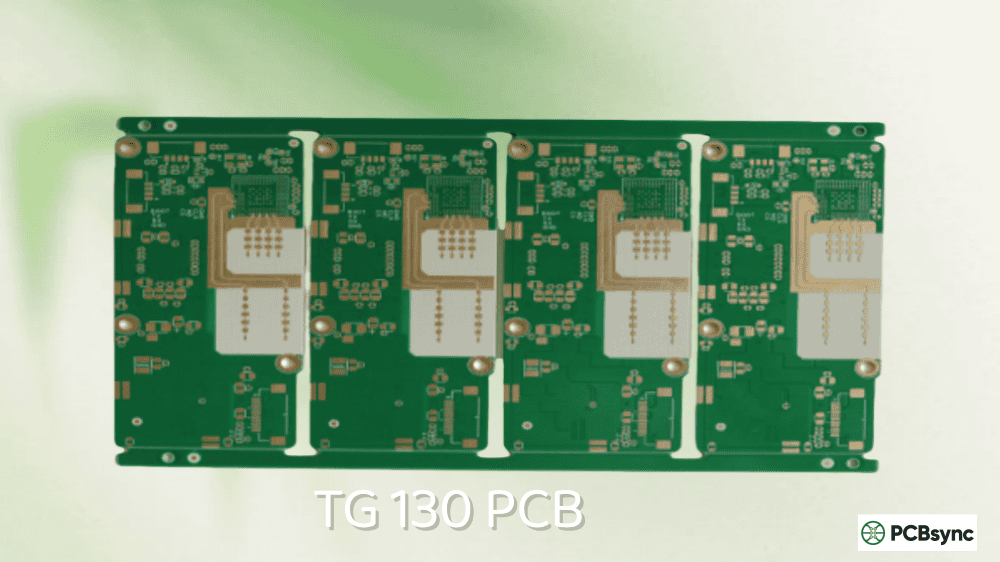
Standard/Low Tg
130-140°C
Basic FR4
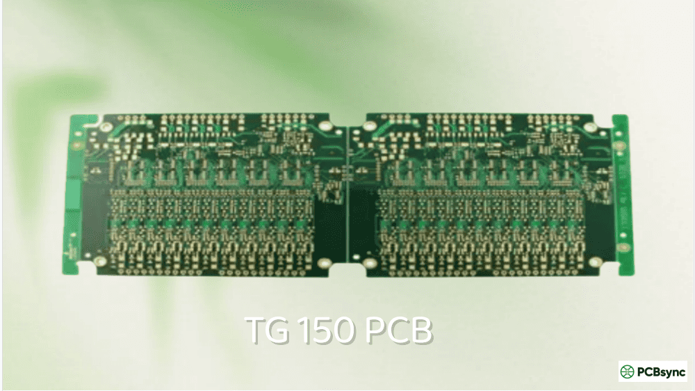
Medium Tg
150-165°C
Mid-Tg FR4
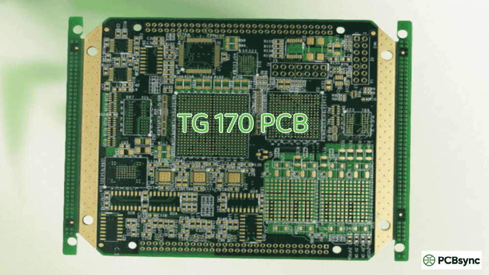
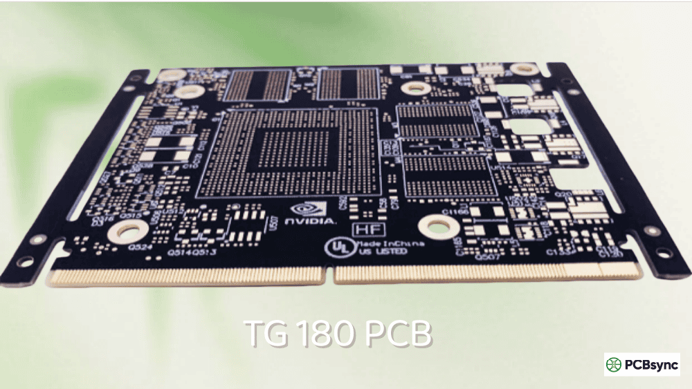
High Tg
≥170°C
High-Tg FR4, Tg 170, Tg 180
The 170°C threshold matters because it represents a significant jump in material performance. High-Tg materials use enhanced resin systems with denser molecular cross-linking, resulting in superior thermal stability, lower Z-axis expansion, and better resistance to the stresses of modern lead-free assembly processes.
Why 170°C Became the Industry Standard
The 170°C benchmark didn’t happen by accident. It emerged from practical requirements:
Lead-Free Soldering: RoHS compliance pushed reflow temperatures from 210-230°C (tin-lead) to 240-260°C (lead-free). Standard Tg 130 materials experience significant stress at these temperatures, while Tg 170+ materials handle the thermal excursion with margin to spare.
Multilayer Reliability: Complex 10+ layer boards undergo multiple lamination cycles at 180-200°C. High-Tg materials maintain dimensional stability through these repeated thermal exposures.
Operating Environment: Modern electronics in automotive, industrial, and aerospace applications routinely operate at 100-150°C ambient temperatures. The 25-30°C safety margin below Tg makes 170°C the minimum for these environments.
FR4 Tg 170 Technical Specifications
Understanding the technical specifications helps you evaluate whether Tg 170 PCB meets your design requirements. These values represent typical ranges across major manufacturers.
Thermal Properties
Property
Typical Value
Test Method
Comparison to Tg 130
Glass Transition Temp (Tg)
170-175°C
DSC (IPC-TM-650)
+40°C higher
Decomposition Temp (Td)
340-350°C
TGA (5% weight loss)
+30-40°C higher
CTE (X/Y axis)
12-14 ppm/°C
IPC-TM-650
Similar
CTE (Z axis) below Tg
40-55 ppm/°C
IPC-TM-650
15-25% lower
CTE (Z axis) above Tg
150-180 ppm/°C
IPC-TM-650
20-30% lower
Thermal Conductivity
0.3-0.4 W/m·K
—
Similar
T260 (Time to Delamination)
>60 minutes
IPC-TM-650
2x longer
T288 (Time to Delamination)
>30 minutes
IPC-TM-650
2x longer
Max Operating Temperature
~145°C
—
+40°C higher
Electrical Properties
Property
Typical Value
Test Method
Dielectric Constant (Dk) @ 1MHz
4.2-4.5
IPC-TM-650
Dissipation Factor (Df) @ 1MHz
0.015-0.020
IPC-TM-650
Volume Resistivity
10⁸-10¹⁰ MΩ·cm
IPC-TM-650
Surface Resistivity
10⁷-10⁹ MΩ
IPC-TM-650
Dielectric Breakdown
45-55 kV/mm
IPC-TM-650
CTI (Comparative Tracking Index)
≥175V
IPC-TM-650
Mechanical Properties
Property
Typical Value
Test Method
Notes
Tensile Strength
420-480 MPa
IPC-TM-650
5-10% higher than Tg 130
Flexural Strength (25°C)
520-580 MPa
IPC-TM-650
Better rigidity
Flexural Strength (150°C)
340-400 MPa
IPC-TM-650
Maintains strength at temp
Peel Strength
1.0-1.4 N/mm
IPC-TM-650
Good copper adhesion
Moisture Absorption
≤0.10%
IPC-TM-650
Low absorption
Flammability
UL94 V-0
UL
Self-extinguishing
Key Benefits of Tg 170 PCB Material
The enhanced specifications translate into real-world performance advantages. Here’s what high-Tg material delivers for demanding applications.
Superior Lead-Free Soldering Performance
This is the primary driver for Tg 170 PCB adoption. Lead-free soldering creates thermal stresses that standard materials struggle to handle:
Assembly Scenario
Standard Tg 130
High Tg 170
Single reflow cycle
Marginal
Excellent
Double-sided reflow
Stressed
Very Good
Multiple reflow (rework)
Not Recommended
Good
Wave soldering
Acceptable
Excellent
Resin weight loss per cycle
1.5-3%
<0.5%
The higher decomposition temperature (Td ~340°C vs ~310°C) means less resin degradation during the 240-260°C lead-free reflow peaks. This translates to fewer assembly defects and improved long-term reliability.
Lower Coefficient of Thermal Expansion
The Z-axis CTE improvement is critical for via reliability and component attachment:
Below Tg: Tg 170 materials exhibit 40-55 ppm/°C Z-axis expansion compared to 55-70 ppm/°C for standard FR4. This 20-25% reduction decreases stress on plated through-holes during thermal cycling.
Above Tg: When temperatures exceed Tg (during soldering), standard materials can spike to 200-250 ppm/°C expansion. High-Tg materials stay in the 150-180 ppm/°C range, significantly reducing barrel cracking risk in vias.
Enhanced Dimensional Stability
High-Tg materials maintain tighter dimensional tolerances during PCB manufacturing:
Better layer-to-layer registration in multilayer stackups
Reduced bow and twist after lamination
More consistent impedance control
Improved fine-pitch component alignment
Improved Moisture and Chemical Resistance
The denser resin cross-linking in Tg 170 materials provides:
Lower moisture absorption rates
Better resistance to processing chemicals
Reduced susceptibility to Conductive Anodic Filament (CAF) formation
Longer shelf life before assembly
Anti-CAF Performance
CAF (Conductive Anodic Filament) formation causes electrical shorts through copper migration along glass fibers. This failure mode is accelerated by moisture, voltage, and temperature. High-Tg materials with enhanced resin systems significantly reduce CAF susceptibility — a critical factor for high-reliability applications with long service life requirements.
Tg 170 PCB vs Tg 130 vs Tg 150 vs Tg 180: Comprehensive Comparison
Choosing the right Tg level requires balancing performance requirements against cost and manufacturability.
The Tg 170 PCB finds its home in applications where thermal performance is non-negotiable. Here are the primary industries and use cases.
Automotive Electronics
Modern vehicles contain extensive electronics operating in challenging thermal environments:
Under-Hood Applications (Tg 170 required):
Engine Control Units (ECUs)
Transmission controllers
Powertrain electronics
Underhood sensors
Battery Management Systems (EV/Hybrid)
DC-DC converters
Ambient temperatures in engine compartments can reach 125-150°C, with thermal spikes even higher. Tg 170 material provides the necessary margin for reliable operation.
Interior Applications (Tg 150-170):
Advanced Driver Assistance Systems (ADAS)
Infotainment systems
Instrument clusters
Body control modules
Aerospace and Defense
Aerospace applications demand the highest reliability under extreme conditions:
Avionics systems
Flight control computers
Radar and communication systems
Satellite electronics
Navigation equipment
Missile guidance systems
These systems experience temperature ranges from -55°C at altitude to 100°C+ on the ground, often with rapid thermal cycling. Tg 170+ materials maintain dimensional stability through these transitions.
Industrial Automation
Factory floor equipment operates in harsh thermal environments:
Motor drives and inverters
PLC controllers
Robotics control systems
Furnace and oven controls
Process automation equipment
Power distribution systems
Telecommunications Infrastructure
5G and network equipment generates significant heat during continuous operation:
5G base station controllers
High-speed routers and switches
Optical transceivers
Data center equipment
Server motherboards
LED and High-Power Lighting
LED drivers and controllers experience sustained elevated temperatures:
High-brightness LED drivers
Outdoor lighting controllers
Industrial lighting systems
Automotive lighting
Many engineers choose Tg 170 FR4 over metal-core PCB (MCPCB) for LED applications where the thermal requirements don’t justify the MCPCB cost premium.
Medical Devices
Equipment requiring sterilization or operating in demanding environments:
Surgical instruments (autoclave exposure)
Medical imaging equipment
Patient monitoring devices
Diagnostic equipment
Design Guidelines for Tg 170 PCB
Proper design practices maximize the benefits of high-Tg material.
Layer Stack Recommendations
Tg 170 material excels in complex multilayer constructions:
What is the maximum operating temperature for Tg 170 PCB?
The practical maximum continuous operating temperature is approximately 140-145°C. Industry guidance suggests operating at least 25-30°C below the Tg value for long-term reliability. Brief temperature excursions during soldering (240-260°C for lead-free) are acceptable since they’re transient, but sustained operation near Tg accelerates material degradation.
Is Tg 170 PCB required for lead-free soldering?
Not absolutely required, but strongly recommended for reliable lead-free assembly. Standard Tg 130 materials can survive lead-free reflow, but they experience significant stress and resin weight loss (1.5-3% per cycle). Tg 170 materials handle lead-free temperatures with minimal degradation (<0.5% weight loss), making them essential for products requiring multiple reflow cycles, rework capability, or high long-term reliability.
How many layers can be reliably manufactured with Tg 170 material?
Tg 170 material reliably supports 20+ layer designs. The improved dimensional stability and lower thermal expansion make it the standard choice for complex multilayer boards with 10+ layers. For very high layer counts (24+ layers) requiring multiple sequential laminations, some engineers prefer Tg 180+ materials for additional thermal margin during repeated processing.
What’s the difference between Tg and Td in PCB materials?
Tg (Glass Transition Temperature) is the point where the material transitions from rigid to flexible — this change is reversible when cooled. Td (Decomposition Temperature) is where the resin chemically breaks down, losing mass — this is irreversible and permanent. For high-reliability applications, both values matter: high Tg maintains mechanical stability during operation, while high Td ensures survival during lead-free soldering without permanent damage.
When should I choose Tg 180 instead of Tg 170?
Consider Tg 180+ when: operating temperatures consistently exceed 130°C, your design requires 20+ layers with multiple lamination cycles, the application is aerospace/military grade with maximum reliability requirements, or thermal cycling is extreme (wide temperature swings). For most high-temperature industrial and automotive applications, Tg 170 provides adequate margin at lower cost. The Tg 180 premium is best reserved for truly demanding scenarios.
Conclusion: Making the Right Tg 170 PCB Decision
The Tg 170 PCB represents the entry point into high-performance PCB materials. It’s not the most expensive option, but it delivers the thermal stability, dimensional control, and assembly reliability that demanding applications require.
Use Tg 170 PCB when:
Operating temperatures exceed 100°C sustained
Lead-free assembly with reliability requirements
Multilayer designs with 10+ layers
Automotive under-hood or aerospace applications
High-power electronics with thermal management needs
Products with long service life expectations
Standard Tg 130 may suffice when:
Operating temperatures stay below 85°C
Simple 2-6 layer consumer electronics
Cost is the primary constraint
Short product lifecycle
The 15-25% material cost premium for Tg 170 is insurance against field failures, assembly defects, and reliability issues. For applications where performance and reliability matter, it’s typically money well spent.
When in doubt, discuss your specific application with your PCB fabricator and laminate supplier. They can provide guidance based on your operating conditions, assembly process, and reliability requirements. The right material choice at the design stage prevents expensive problems later.
This guide reflects practical engineering experience with high-Tg PCB material selection. Specific properties vary by manufacturer — always verify values against your laminate supplier’s current datasheet for production material.
Inquire: Call 0086-755-23203480, or reach out via the form below/your sales contact to discuss our design, manufacturing, and assembly capabilities.
Quote: Email your PCB files to Sales@pcbsync.com (Preferred for large files) or submit online. We will contact you promptly. Please ensure your email is correct.
Notes: For PCB fabrication, we require PCB design file in Gerber RS-274X format (most preferred), *.PCB/DDB (Protel, inform your program version) format or *.BRD (Eagle) format. For PCB assembly, we require PCB design file in above mentioned format, drilling file and BOM. Click to download BOM template To avoid file missing, please include all files into one folder and compress it into .zip or .rar format.


