Inquire: Call 0086-755-23203480, or reach out via the form below/your sales contact to discuss our design, manufacturing, and assembly capabilities.
Quote: Email your PCB files to Sales@pcbsync.com (Preferred for large files) or submit online. We will contact you promptly. Please ensure your email is correct.
Notes: For PCB fabrication, we require PCB design file in Gerber RS-274X format (most preferred), *.PCB/DDB (Protel, inform your program version) format or *.BRD (Eagle) format. For PCB assembly, we require PCB design file in above mentioned format, drilling file and BOM. Click to download BOM template To avoid file missing, please include all files into one folder and compress it into .zip or .rar format.
After spending 15 years designing RF circuits, I can tell you that material selection makes or breaks a high-frequency project. When signals push beyond 5 GHz, standard FR4 boards start falling apart—literally losing your signal to the substrate. That’s where Teflon PCBs come in.
A Teflon PCB uses polytetrafluoroethylene (PTFE) as its base substrate material instead of traditional FR4 epoxy-glass laminate. DuPont trademarked the name “Teflon” back in 1941 after chemist Roy Plunkett accidentally discovered PTFE in 1938 while working on refrigerants. The same properties that make your non-stick frying pan work—low friction, chemical inertness, and thermal stability—make PTFE an exceptional material for high-frequency circuit boards.
The key difference? PTFE’s dielectric constant sits around 2.1 compared to FR4’s 4.3-4.8. Lower dielectric constant means faster signal propagation and significantly reduced signal loss at microwave frequencies. I’ve seen designs where switching from FR4 to PTFE cut insertion loss by 60% at 10 GHz.
Understanding PTFE’s material properties helps you decide when it’s worth the premium cost. Here’s what actually matters for circuit design:
Electrical Characteristics
PTFE delivers a dielectric constant between 2.1 and 2.5, depending on the specific formulation. This low Dk value allows signals to travel faster through your board. The dissipation factor (Df) typically ranges from 0.0009 to 0.002 at 10 GHz—roughly ten times lower than FR4. In practical terms, this means your 77 GHz automotive radar antenna actually works instead of turning into an expensive paperweight.
The dielectric properties remain remarkably stable across frequency ranges from 1 MHz to over 100 GHz. This consistency simplifies impedance control calculations and reduces the iterative prototyping cycles that drive up development costs.
Teflon PCB Calculator
PCBSync Engineering Tools
Microstrip Impedance Calculator for Teflon PCB
Characteristic Impedance
–Ω
Effective Dk
–
Propagation Delay
–ps/in
Stripline Impedance Calculator
Stripline Impedance
–Ω
Propagation Delay
–ps/in
Teflon/PTFE Material Comparison Chart
Material
Dk @10GHz
Df @10GHz
Frequency
Cost Level
Application
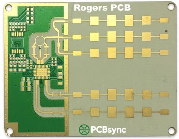
Rogers RT/duroid 5880
2.20
0.0009
Up to 77 GHz
High
Aerospace, Radar
Rogers RT/duroid 5870
2.33
0.0012
Up to 40 GHz
High
Microwave, Satellite
Rogers RO3003
3.00
0.0010
Up to 40 GHz
Medium-High
Automotive Radar
Rogers RO4003C
3.55
0.0027
Up to 20 GHz
Medium
5G, Base Stations
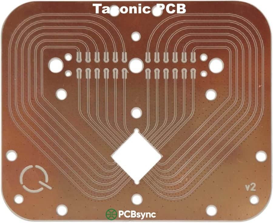
Taconic TLY-5
2.17
0.0009
Up to 60 GHz
High
Military, Space
Taconic RF-35
3.50
0.0018
Up to 15 GHz
Medium
Wireless, IoT
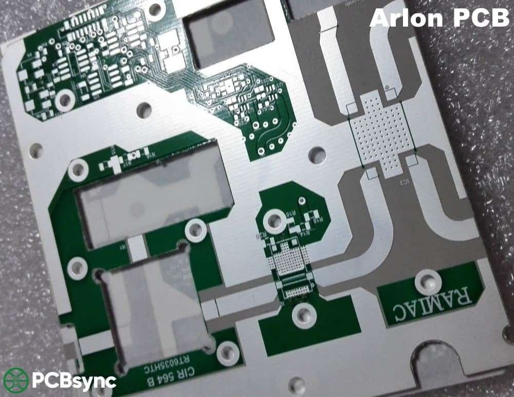
Arlon DiClad 880
2.17
0.0009
Up to 40 GHz
High
Antenna, Radar
Isola Astra MT77
3.00
0.0017
Up to 30 GHz
Medium
5G mmWave
Material Selection Guide
Recommended Material
–
Teflon PCB Manufacturing Cost Estimator
×
Base Material Cost$0
Processing Cost$0
Surface Finish$0
Additional Options$0
Total Estimated Cost$0
Unit Price
$0
Lead Time
–
Note: This is an estimate only. Actual pricing depends on design complexity, current material availability, and specific requirements. Contact PCBSync for accurate quotation.
Teflon PCB Stackup Configuration
Select stackup type to view configuration
Hybrid Stackup Benefits
Cost Optimization: Use Teflon only for RF layers and FR4 for power/ground planes to reduce material costs by 30-50%.
Signal Integrity: Teflon layers provide low loss for high-frequency signals while FR4 offers mechanical stability.
Manufacturing: Hybrid stackups require careful bonding process – use appropriate prepreg materials.
Teflon PCB Design Guidelines
1. Material Storage: Store Teflon laminates in a controlled environment (20-25°C, <50% RH). PTFE materials can absorb moisture affecting Dk values.
2. Drilling Considerations: Use carbide drills with 130° point angle. Reduce feed rate by 30-50% compared to FR4. Consider controlled-depth drilling for blind vias.
3. Surface Preparation: Plasma treatment or sodium etch is required for proper adhesion. ENIG finish is recommended for consistent impedance and solderability.
4. Trace Design: Maintain consistent trace width. Use smooth transitions for impedance changes. Avoid sharp corners – use 45° or curved traces for RF paths.
5. Via Design: Use back-drilled or blind vias to minimize stub effects at high frequencies. Keep via-to-trace transitions short.
6. Ground Plane: Use solid ground planes without splits under RF traces. Place ground vias around RF traces for isolation (via stitching).
7. Thermal Management: PTFE has lower thermal conductivity than FR4. Use thermal vias and consider copper coin inserts for heat dissipation.
8. Layer Alignment: Account for CTE differences in hybrid stackups. Use proper registration marks for multi-layer alignment.
Common Mistakes to Avoid
✗ Using standard FR4 design rules without accounting for Teflon properties
✗ Ignoring via stubs in high-frequency designs (>10 GHz)
✗ Insufficient ground via stitching near RF traces
✗ Not specifying impedance tolerance in fabrication notes
✗ Using incompatible prepreg for hybrid stackups
Frequency vs. Material Selection Quick Reference
Frequency Range
Recommended Materials
Key Consideration
< 6 GHz
RO4003C, RF-35, Standard PTFE
Cost-effective solutions work well
6 – 20 GHz
RO3003, RT/duroid 5870
Balance Dk stability and loss
20 – 40 GHz
RT/duroid 5880, TLY-5
Ultra-low loss critical
> 40 GHz
RT/duroid 5880, Specialized PTFE
Lowest Df, tight Dk tolerance
Thermal Performance
PTFE handles temperatures from -200°C to +260°C without degrading—a range that makes aerospace engineers sleep better at night. The glass transition temperature (Tg) exceeds 280°C, far surpassing FR4’s typical 130-170°C range. For power amplifiers and circuits that generate significant heat, this headroom prevents delamination failures that plague lower-grade materials.
Chemical and Environmental Resistance
PTFE resists practically every chemical you’ll encounter in industrial and aerospace environments—acids, bases, solvents, and fuels. Moisture absorption sits below 0.01%, ensuring consistent electrical performance even in humid conditions or marine applications. This chemical inertness also makes PTFE boards suitable for medical devices that undergo repeated sterilization cycles.
PTFE vs FR4: Head-to-Head Comparison
Before committing to PTFE, you need to understand exactly how it stacks up against FR4. This comparison covers the specifications that actually impact your design decisions:
Property
PTFE (Teflon)
FR4
Impact
Dielectric Constant (Dk)
2.1 – 2.5
4.3 – 4.8
Signal speed & trace width
Dissipation Factor (Df)
0.0009 – 0.002
0.02 – 0.025
Signal loss at high freq
Operating Temp
-200°C to +260°C
-40°C to +130°C
Environmental limits
Glass Transition (Tg)
>280°C
130-170°C
Thermal stability
Moisture Absorption
<0.01%
0.1-0.2%
Performance consistency
Dielectric Strength
1000 V/mil
300-500 V/mil
Voltage handling
Relative Cost
5-10x higher
Baseline
Project budget
The practical takeaway: use PTFE when operating above 2-3 GHz and FR4 becomes a liability. For frequencies below 1 GHz, FR4 usually provides adequate performance at a fraction of the cost.
Types of PTFE PCB Materials
Pure PTFE alone doesn’t make a practical PCB substrate—it’s too soft and has adhesion problems with copper. Commercial PTFE laminates add reinforcements and fillers to create usable materials. Here are the main categories:
Woven Glass Reinforced PTFE
These laminates use woven fiberglass fabric coated with PTFE resin. Examples include Rogers CuClad series and Taconic TLY-5. The woven structure provides excellent dimensional stability and mechanical strength while maintaining low dielectric loss. TLY-5, for instance, delivers Dk values around 2.2 with dissipation factors as low as 0.0009 at 10 GHz—making it popular for 77 GHz automotive radar applications.
Ceramic-Filled PTFE
Adding ceramic particles to PTFE creates materials with tailored dielectric constants while maintaining low loss. Rogers RO3003 uses ceramic fillers to achieve a stable Dk of 3.0 across wide temperature and frequency ranges. This stability makes ceramic-filled PTFE ideal for 5G infrastructure and aerospace applications where environmental conditions vary dramatically.
Microfiber Glass Reinforced PTFE
Rogers RT/duroid 5880 represents this category, using randomly oriented microfibers instead of woven fabric. This construction yields Dk values around 2.2 with exceptional uniformity across the laminate surface. The RT5880 has become a standard for satellite communications and military radar systems due to its ultra-low loss characteristics.
Teflon PCBs appear wherever high-frequency performance is non-negotiable. Here’s where the material truly earns its premium price:
5G and Telecommunications
The rollout of 5G networks has driven massive demand for PTFE boards. Base station equipment operates at 28 GHz and 39 GHz frequencies where FR4 simply cannot perform. Massive MIMO antennas with dozens of antenna elements require phase-matched feed networks—something only achievable with PTFE’s consistent dielectric properties. Beamforming networks, power amplifiers, and filter banks in 5G infrastructure commonly use Rogers RO3003 or Taconic TLY-5 materials.
Aerospace and Satellite Systems
Satellite transponders, phased-array antennas, and Ka-band communication systems rely on PTFE’s stability across extreme temperature cycling. In orbit, electronics face temperature swings from -150°C to +150°C—conditions that would destroy FR4 boards within days. The RT5880 and RT6002 series dominate this space due to their low outgassing characteristics and radiation resistance, which prevent performance degradation over multi-year missions.
Automotive Radar and ADAS
Modern vehicles pack 77 GHz radar sensors for adaptive cruise control, collision avoidance, and autonomous driving features. At these frequencies, every tenth of a dB matters for detection range. Automotive radar modules typically use low-loss PTFE laminates like TLY-5 or RO3003, which maintain consistent performance despite engine compartment temperature variations and vehicle vibration.
Defense and Radar Systems
Military radar, electronic warfare equipment, and missile guidance systems demand the highest reliability under the harshest conditions. The RT6000 series laminates meet MIL-spec requirements for defense applications. These boards must operate from desert heat to Arctic cold while maintaining precise electrical characteristics that determine whether a radar system detects threats accurately.
Medical Electronics
MRI coils, RF amplifiers in imaging equipment, and medical telemetry devices benefit from PTFE’s chemical resistance and sterilization compatibility. Medical applications also leverage PTFE’s biocompatibility in implantable devices where the substrate contacts bodily fluids.
Manufacturing Challenges and Solutions
Working with PTFE isn’t like processing standard FR4. The same properties that make it excellent for high-frequency circuits create significant fabrication challenges. Here’s what your manufacturer needs to handle:
Drilling Operations
PTFE’s softness causes it to deform under drill pressure rather than cutting cleanly. Standard drilling speeds produce smeared hole walls that prevent proper copper plating adhesion. Manufacturers use high-speed spindles running 70,000-100,000 RPM with specially designed bit geometries and slow feed rates. Laser drilling provides cleaner results for microvias but increases processing costs.
Surface Preparation and Plating
Remember that non-stick property from your frying pan? It makes copper refuse to bond with PTFE surfaces. Plasma treatment or sodium etching activates the PTFE surface before copper deposition. Without this step, you’ll see delamination failures during thermal cycling or soldering. The plated copper also needs high tensile strength to accommodate PTFE’s higher coefficient of thermal expansion—around 200 ppm/°C in the Z-axis for pure PTFE.
Lamination Process
Multilayer PTFE boards require precise temperature and pressure control during lamination. Unlike FR4, PTFE substrates don’t need oxide pretreatment. Lamination occurs at temperatures up to 370°C and pressures of 450-500 PSI using vacuum presses to ensure void-free bonds. Some fabricators use low-melting-point bonding films to reduce processing temperatures for hybrid PTFE-FR4 stackups.
Solder Mask Application
Standard solder masks have poor adhesion to PTFE’s slippery surface. Manufacturers must apply solder mask within 12 hours of etching and often bake the boards first to eliminate residual moisture. High CTE mismatch between solder mask and substrate can cause cracking during thermal cycling if the wrong mask chemistry is selected.
Cost Factors and Budget Planning
Let’s talk money—because PTFE boards cost significantly more than FR4, and understanding where those costs come from helps you make smarter design decisions.
Material Costs
PTFE laminates themselves run 5-10 times more expensive than equivalent FR4 sheets. Military-grade materials like the RT6000 series cost even more due to tighter specifications and additional qualification testing. Some specialty laminates, like the Rogers RT7000 series for military radar, have limited availability and extended lead times that can stretch to 8-12 weeks.
Processing Costs
The specialized drilling, plating, and lamination processes for PTFE require dedicated equipment and trained operators. Not every PCB shop can handle PTFE—and those that can charge premium rates. Expect fabrication costs 3-5 times higher than comparable FR4 boards. Prototype quantities often face minimum order charges since manufacturers batch PTFE jobs to justify setup time.
Cost Optimization Strategies
Use hybrid stackups—PTFE only for RF layers, FR4 for DC and logic sections
Consider Rogers 4350B for cost-sensitive designs below 10 GHz (processes like FR4)
Source from Asian manufacturers for non-military applications—costs run 40-60% lower
Design for standard panel sizes to minimize material waste
Order in volume when possible—PTFE MOQ requirements make small batches expensive
How to Select the Right PTFE Material
Choosing between PTFE options requires balancing electrical performance, processability, and cost. Here’s my decision framework after years of RF designs:
Frequency-Based Selection
Below 2 GHz: FR4 usually works fine—save your budget
2-6 GHz: Rogers 4350B or 4003C (hydrocarbon ceramic, easier to process)
6-40 GHz: RO3003, TLY-5, or RT5880 depending on loss requirements
Above 40 GHz: Pure PTFE materials like RT5880 for ultra-low loss
Application Considerations
Satellite/aerospace: RT5880 or RT6002 for temperature stability and low outgassing
5G base stations: RO3003 for phase stability across large antenna arrays
Automotive radar: TLY-5 balances performance with automotive qualification requirements
Power amplifiers: RF-35 or similar ceramic-filled materials for thermal management
Frequently Asked Questions
What is the difference between Teflon PCB and Rogers PCB?
“Teflon PCB” refers to any board using PTFE-based materials, while “Rogers PCB” specifically means boards using Rogers Corporation laminates. Not all Rogers materials contain PTFE—the popular RO4000 series uses hydrocarbon ceramics without PTFE. True Teflon/PTFE Rogers products include the RT5000, RT6000, and RO3000 series. Think of it this way: all PTFE boards are high-frequency boards, but not all Rogers boards are PTFE boards.
Can Teflon PCBs be soldered using standard processes?
Yes, but with precautions. PTFE boards tolerate lead-free soldering temperatures (260°C peak) without structural damage. However, the surface preparation is critical—poorly activated PTFE surfaces cause solder mask peeling and pad lifting. Pre-bake the boards at 105°C for 2-4 hours before reflow to eliminate absorbed moisture. Use nitrogen atmosphere during reflow for best results, and ensure your assembly house has experience with high-frequency materials.
How much more expensive are Teflon PCBs compared to FR4?
Expect to pay 5-10 times more for raw materials and 3-5 times more for fabrication compared to equivalent FR4 boards. A simple two-layer FR4 prototype might cost $50-100, while the same design in RT5880 could run $400-800. Military-grade PTFE boards with additional certifications push costs even higher. Volume production narrows the gap somewhat, but PTFE never approaches FR4 pricing. Budget accordingly and justify the premium through improved system performance.
What frequency range requires Teflon PCB materials?
The cutoff isn’t absolute—it depends on your loss budget and performance requirements. As a general guideline: consider PTFE above 2-3 GHz for demanding applications, and definitely use PTFE above 6 GHz for any serious RF work. At 77 GHz automotive radar frequencies, PTFE is essential. However, I’ve designed successful 900 MHz systems on FR4 and struggling 3 GHz systems that needed PTFE—context matters. Simulate your design and calculate whether FR4 losses are acceptable before committing to PTFE costs.
How should Teflon PCB materials be stored?
Store PTFE laminates in climate-controlled conditions at room temperature (18-25°C) away from direct sunlight. Most manufacturers recommend using materials within 45 days of receipt for optimal quality—the surface can oxidize over time, affecting copper adhesion during fabrication. Keep boards in their original vacuum-sealed packaging until ready to process. If storing unpanelized laminates, stack them flat with interleaving paper to prevent surface contamination or scratching of the delicate PTFE surface.
Additional Resources
Deepen your understanding of PTFE PCB technology with these authoritative resources:
Getting a PTFE design from schematic to working prototype requires attention to details that standard FR4 designs forgive. Here are lessons learned from real projects:
Impedance Control Considerations
PTFE’s lower dielectric constant means wider traces for the same impedance compared to FR4. A 50-ohm microstrip that requires a 12-mil trace on 10-mil FR4 might need a 24-mil trace on equivalent PTFE. This affects routing density and board size—plan accordingly during the schematic phase. Use electromagnetic simulation tools to verify impedance calculations, as handbook formulas lose accuracy above 10 GHz.
The stable Dk of PTFE materials simplifies impedance control across temperature ranges. Where FR4’s dielectric constant shifts with temperature (causing impedance drift), PTFE maintains consistent values. This stability reduces the need for calibration circuits in precision RF systems.
Via Design and Transitions
Signal vias become significant discontinuities at microwave frequencies. Use via stitching around RF traces to maintain ground reference and reduce radiation losses. For layer transitions, implement via stubs compensation or backdrilling to eliminate resonances. At 77 GHz, even a 5-mil stub can create a notch filter that destroys your signal. Ground via fencing around transmission lines improves isolation between channels—critical for multichannel radar and phased array designs.
Thermal Management Integration
While PTFE handles high temperatures structurally, its thermal conductivity (around 0.25-0.40 W/mK) is lower than FR4. Power amplifiers and high-current circuits need proper thermal design. Use thermal vias under hot components to conduct heat to internal ground planes or metal backing. Some designs benefit from hybrid constructions with metal-core substrates for the thermal layers and PTFE only for the RF circuits.
Assembly Process Planning
Coordinate with your assembly house before finalizing the design. PTFE boards require modified reflow profiles—typically lower ramp rates to prevent thermal shock. Component placement accuracy becomes more critical because rework on PTFE substrates risks pad lifting. Design for test points and inspection access to minimize rework needs. Consider using temperature indicators during first article runs to verify actual board temperatures match your profile.
Working with PCB Manufacturers
Finding a capable PTFE fabrication partner prevents months of frustration. Here’s how to evaluate and collaborate with manufacturers:
Qualifying Your Fabricator
Ask potential manufacturers about their specific experience with your chosen material. A shop that excels at RO4350B may struggle with pure PTFE like RT5880. Request references from similar projects and review their equipment list—PTFE requires plasma treatment systems, specialized drilling equipment, and controlled atmosphere lamination presses. Verify they maintain material inventory or have short lead times from distributors; PTFE laminate supply chain disruptions can delay projects by months.
Design for Manufacturing Communication
Share your design files early for DFM review—before final release. Good fabricators identify problematic features like tight via-to-trace clearances, thin copper on high-aspect-ratio holes, or stackup combinations that cause CTE stress. Their feedback costs nothing and saves expensive respins. Specify your critical features clearly: which dimensions are critical-to-function, what impedance tolerances you actually need, and where you can accept relaxed specifications to improve yield.
Test Coupon Requirements
For production volumes, require impedance test coupons on every panel. These coupons verify that the actual fabrication matches your designed impedance values. TDR (time-domain reflectometry) measurements on coupons catch process drift before it affects your assemblies. Some high-reliability applications also require microsection samples to verify copper plating thickness, via fill quality, and layer registration on PTFE multilayer boards.
Future Trends in PTFE PCB Technology
The high-frequency materials landscape continues evolving as application demands push into millimeter-wave and terahertz ranges. Understanding these trends helps with long-term technology roadmap planning:
Emerging Applications Driving Innovation
The proliferation of 5G mmWave networks, automotive radar beyond 77 GHz, and emerging 6G research at 100+ GHz frequencies push material requirements further. Next-generation PTFE formulations target even lower loss tangents while maintaining processability. Satellite internet constellations like Starlink create massive demand for ground terminal PCBs operating at Ka-band (26-40 GHz), driving both material innovation and PCB manufacturing scale-up.
Hybrid Construction Advances
Advanced hybrid stackups combining PTFE RF layers with high-speed digital substrates enable single-board solutions for complex systems. New bonding materials provide reliable interconnection between dissimilar dielectrics while maintaining controlled impedance across transitions. These hybrids reduce system size and cost for applications like 5G small cells where RF, digital processing, and power management share a single substrate.
Sustainability Considerations
Environmental regulations increasingly scrutinize fluoropolymers including PTFE. While current materials remain available, the industry explores alternative high-frequency substrates with reduced environmental impact. Designers should monitor regulatory developments, particularly in the European Union, that may affect long-term material availability or require design changes for certain applications.
Final Thoughts
Teflon PCBs aren’t just “better FR4″—they’re a fundamentally different technology that enables RF and microwave systems impossible with standard materials. The higher cost makes sense when you consider that a failed radar system or dropped 5G connection costs far more than the substrate price difference.
Start with a clear understanding of your frequency requirements, loss budget, and environmental conditions. Match those requirements to the right PTFE material family. Work with fabricators experienced in high-frequency materials—not every shop can properly process PTFE. And simulate before you fabricate, because respins in PTFE boards hit your schedule and budget hard.
Whether you’re designing 5G infrastructure, automotive radar, satellite communications, or defense electronics, PTFE materials provide the foundation for systems that actually work at microwave frequencies. Choose wisely, process carefully, and your high-frequency designs will perform as intended.
Inquire: Call 0086-755-23203480, or reach out via the form below/your sales contact to discuss our design, manufacturing, and assembly capabilities.
Quote: Email your PCB files to Sales@pcbsync.com (Preferred for large files) or submit online. We will contact you promptly. Please ensure your email is correct.
Notes: For PCB fabrication, we require PCB design file in Gerber RS-274X format (most preferred), *.PCB/DDB (Protel, inform your program version) format or *.BRD (Eagle) format. For PCB assembly, we require PCB design file in above mentioned format, drilling file and BOM. Click to download BOM template To avoid file missing, please include all files into one folder and compress it into .zip or .rar format.


