Inquire: Call 0086-755-23203480, or reach out via the form below/your sales contact to discuss our design, manufacturing, and assembly capabilities.
Quote: Email your PCB files to Sales@pcbsync.com (Preferred for large files) or submit online. We will contact you promptly. Please ensure your email is correct.
Notes: For PCB fabrication, we require PCB design file in Gerber RS-274X format (most preferred), *.PCB/DDB (Protel, inform your program version) format or *.BRD (Eagle) format. For PCB assembly, we require PCB design file in above mentioned format, drilling file and BOM. Click to download BOM template To avoid file missing, please include all files into one folder and compress it into .zip or .rar format.
How to Generate Gerber Files in Fusion 360: A Complete Engineering Guide
Generating accurate Gerber files is a critical step in transitioning from PCB design to manufacturing. Autodesk Fusion 360 offers multiple export methods that give engineers flexibility and control over their production output. This comprehensive guide walks through each approach to generating Gerber files in Fusion 360, ensuring your designs reach fabrication houses with all necessary data intact.
Understanding Gerber Files and Their Role in PCB Manufacturing
Gerber files serve as the universal language between PCB designers and manufacturers. These industry-standard files (RS-274X format) contain all the geometric information required to fabricate each layer of your printed circuit board. A complete Gerber package typically includes copper layers, solder mask layers, silkscreen layers, paste layers, and board outline definitions.
Beyond Gerber files, manufacturers require NC drill files (Excellon format) specifying hole positions, sizes, and types. Fusion 360’s CAM processor handles both file types, streamlining the export workflow for engineers working on prototypes or production runs.
Prerequisites Before Exporting
Before initiating the Gerber export process, ensure your design passes Design Rule Check (DRC) validation. Fusion 360’s integrated DRC tool identifies clearance violations, unconnected nets, and other potential manufacturing issues. Address all errors and review warnings before proceeding—fabrication houses will reject files containing critical violations.
Additionally, verify that your layer stackup matches your intended board configuration. For multilayer designs, confirm that internal plane assignments and layer ordering align with your manufacturer’s capabilities and your design requirements.
Method One: Using CAM Preview for Gerber Export
The CAM Preview approach provides a visual verification step before committing to file generation. This method is particularly valuable when validating complex designs or when working with unfamiliar stackup configurations.
To access CAM Preview, navigate to MANUFACTURING > MANUFACTURING > CAM Preview from the main toolbar. The Manufacturing Preview window renders your board’s layers, allowing visual inspection of copper pours, trace routing, and component placements before export.
From the Manufacturing Preview window, click the CAM Processor button located in the bottom right corner. This transitions you to the CAM Processor interface where actual file generation occurs.
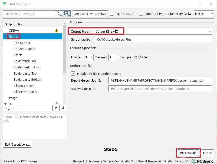
Within the CAM Processor dialog, click the document icon adjacent to the CAM file name field. Select Load CAM jobs > examples and choose the appropriate job file matching your layer count. For a standard two-layer board, select “example_2_layer.cam”—Fusion 360 includes templates for common configurations including 4-layer and 6-layer stackups.
On the left panel, select Gerber and verify the Output Type remains set to Gerber RS-274X. This format ensures compatibility with virtually all PCB fabrication houses worldwide. Click Process Job and specify your output directory. Fusion 360 generates individual Gerber files for each layer plus accompanying drill files.
Method Two: Direct CAM Processor Access
Engineers familiar with CAM workflows can bypass the preview step by accessing the CAM Processor directly. Navigate to MANUFACTURING > MANUFACTURING > CAM Processor to open the processing dialog immediately.
The subsequent workflow mirrors Method One: load the appropriate CAM job template, configure output settings, and execute the job. This streamlined approach reduces clicks for experienced users who have already verified their designs through other means.
The CAM Processor interface provides granular control over individual layer exports. Engineers can selectively enable or disable specific outputs, adjust aperture settings, and configure drill file parameters. This flexibility proves valuable when regenerating only specific layers after design modifications.
Method Three: Quick Export via Gerber Output Command
Fusion 360’s third export option prioritizes speed and simplicity. Access this method through MANUFACTURING > MANUFACTURING > Export Gerber, NC Drill, Assembly and Drawing Outputs. This command bypasses the CAM Processor interface entirely, presenting a consolidated file list for immediate export.
The CAM Export File List window displays all exportable files including profile (board outline), copper layers, soldermask, solderpaste, and drill files. Review the file list to confirm all necessary layers appear—missing layers indicate potential design issues requiring attention.
Click OK, select your destination folder, and click Save. Fusion 360 automatically packages all files into a ZIP archive, ready for direct upload to your manufacturer’s quoting system. This archive structure eliminates manual file organization and reduces the risk of omitting critical files during submission.
Understanding Generated File Types
A complete Fusion 360 Gerber export produces several file categories that engineers should understand.
Copper layer files (.GTL for top, .GBL for bottom, .G2/.G3 for internal layers) define all conductive traces, pads, and copper pours. Soldermask files (.GTS for top, .GBS for bottom) specify areas where soldermask should be absent, exposing copper for soldering. Silkscreen files (.GTO for top, .GBO for bottom) contain component designators, polarity markings, and other textual annotations.
The board outline file (.GKO or .GM1) defines the physical board boundary and any internal cutouts. Paste layer files (.GTP for top, .GBP for bottom) guide stencil fabrication for SMT assembly processes.
NC drill files (.DRL or .XLN) use Excellon format to specify all hole locations and diameters. Some manufacturers require separate files for plated through-holes versus non-plated holes—verify your fabricator’s requirements.
Best Practices for Production-Ready Exports
Maintaining organized project structures simplifies the export process and reduces errors. Create dedicated output folders for each board revision, clearly labeled with version numbers and dates. This practice facilitates design iteration tracking and prevents accidental submission of outdated files.
Always verify exported files before submission using a standalone Gerber viewer. Tools like GerbView, ViewMate, or web-based viewers allow layer-by-layer inspection independent of Fusion 360. Check for proper layer alignment, verify drill hit positions correspond to pad centers, and confirm board outline accuracy.
Include a README file with your Gerber package specifying layer stackup, finished board thickness, copper weight, surface finish requirements, and any special fabrication notes. Clear documentation reduces manufacturer questions and accelerates quoting cycles.
Troubleshooting Common Export Issues
Missing layers in the export typically indicate incomplete CAM job configuration. Ensure your selected CAM job template matches your actual layer count. For custom stackups, modify template files or create new CAM jobs reflecting your specific configuration.
If drill files appear empty or contain incorrect hole counts, verify that your design includes properly defined drills rather than just pads. Fusion 360 distinguishes between pad geometry and actual drill specifications—both must be correctly defined.
Gerber files showing unexpected content may result from incorrect layer mapping. Review the CAM Processor’s layer assignment settings to confirm each output file draws from the correct design layer. Mixed-up assignments commonly occur when modifying existing CAM jobs for different stackup configurations.
Manufacturer Submission Considerations
Different PCB fabrication houses maintain varying file requirements and naming conventions. Before submitting your Gerber package, review your manufacturer’s specifications document. Some fabricators require specific file extensions or naming patterns that differ from Fusion 360’s defaults.
Layer count verification remains essential—ensure your package contains exactly the number of copper layers your manufacturer expects. Submitting a two-layer Gerber set when ordering a four-layer board creates costly delays and potential re-spins.
Many manufacturers offer online Gerber viewers integrated into their quoting systems. Use these tools as a final verification step, comparing the manufacturer’s rendering against your design intent before committing to production.
Conclusion
Fusion 360 provides robust Gerber generation capabilities suitable for professional PCB development workflows. Whether using CAM Preview for visual verification, the direct CAM Processor for granular control, or the quick export command for streamlined output, engineers can produce manufacturing-ready files efficiently.
Mastering these export methods ensures smooth transitions from design to fabrication, minimizing delays caused by file format issues or missing data. Combined with thorough pre-export verification and clear manufacturer communication, Fusion 360’s Gerber tools support reliable, repeatable PCB production processes.
Inquire: Call 0086-755-23203480, or reach out via the form below/your sales contact to discuss our design, manufacturing, and assembly capabilities.
Quote: Email your PCB files to Sales@pcbsync.com (Preferred for large files) or submit online. We will contact you promptly. Please ensure your email is correct.
Notes: For PCB fabrication, we require PCB design file in Gerber RS-274X format (most preferred), *.PCB/DDB (Protel, inform your program version) format or *.BRD (Eagle) format. For PCB assembly, we require PCB design file in above mentioned format, drilling file and BOM. Click to download BOM template To avoid file missing, please include all files into one folder and compress it into .zip or .rar format.


