Inquire: Call 0086-755-23203480, or reach out via the form below/your sales contact to discuss our design, manufacturing, and assembly capabilities.
Quote: Email your PCB files to Sales@pcbsync.com (Preferred for large files) or submit online. We will contact you promptly. Please ensure your email is correct.
Notes: For PCB fabrication, we require PCB design file in Gerber RS-274X format (most preferred), *.PCB/DDB (Protel, inform your program version) format or *.BRD (Eagle) format. For PCB assembly, we require PCB design file in above mentioned format, drilling file and BOM. Click to download BOM template To avoid file missing, please include all files into one folder and compress it into .zip or .rar format.
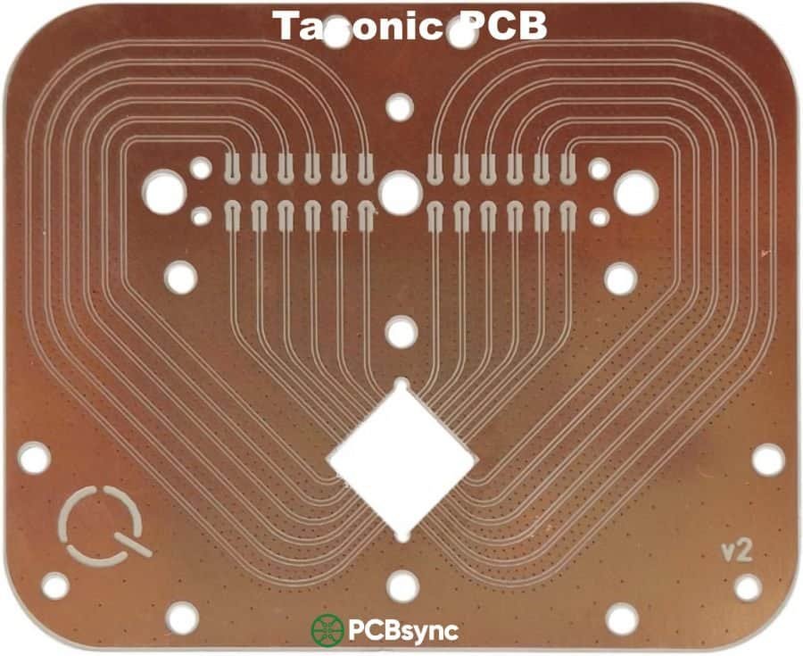
If you’ve spent any time designing RF circuits or high-frequency systems, you’ve probably hit the wall with standard FR-4. Signal loss at 2 GHz, unstable impedance, and thermal drift—it’s frustrating when your simulations look great but your boards don’t perform. That’s exactly where Taconic PCB materials come in.
Having worked with various high-frequency laminates over the years, I can tell you that Taconic materials have earned their place in the RF engineer’s toolkit. They’re not the cheapest option, but when you need consistent performance from satellite communications to automotive radar, these PTFE-based substrates deliver where FR-4 simply can’t.
This guide covers everything you need to know about Taconic PCB materials—from fundamental properties to practical design considerations. Whether you’re specifying your first RF-35 board or comparing options for a 77 GHz radar module, you’ll find the technical details and real-world insights here.
Taconic PCB materials are high-performance laminates manufactured by Taconic Advanced Dielectric Division—now part of AGC (Asahi Glass Company) following their 2019 acquisition. Founded in 1961, Taconic pioneered the process for applying PTFE (polytetrafluoroethylene) to fiberglass fabric, and they’ve been refining high-frequency substrates ever since.
What makes Taconic different from your standard PCB material? It comes down to composition. While FR-4 uses epoxy resin with woven glass reinforcement, Taconic materials are built on PTFE—commonly known as Teflon—combined with ceramic fillers or glass fiber reinforcement. This fundamental difference translates to dramatically lower signal loss and more stable electrical properties across frequency and temperature.
The dielectric constant (Dk) range spans from 2.17 to 10.0, covering frequencies from 2 GHz all the way up to 110 GHz. That’s a massive operating window compared to FR-4, which starts showing significant losses above 1-2 GHz.
For accurate specifications, refer to official Taconic datasheets
Key Properties of Taconic Laminates
Understanding the core properties helps you select the right material for your application. Here’s what matters for high-frequency design:
Low Dielectric Constant (Dk)
Taconic materials offer Dk values ranging from 2.17 (TLY series) to 10.0 (CER-10), with tight tolerances of ±0.02 to ±0.05. A lower Dk means faster signal propagation and reduced signal delay—critical for timing-sensitive applications. The stability of this value across frequency and temperature sets Taconic apart from commodity materials.
Low Dissipation Factor (Df)
This is where Taconic really shines. The dissipation factor (loss tangent) measures how much electromagnetic energy gets absorbed as heat. TLY-5 achieves an incredibly low Df of 0.0009 at 10 GHz, while RF-35 comes in at 0.0019. Compare that to FR-4’s typical Df of 0.02—that’s roughly 10-20x more signal loss with standard materials.
Thermal Stability
RF-35 has a glass transition temperature (Tg) exceeding 315°C, making it compatible with lead-free soldering processes. The Z-axis coefficient of thermal expansion (CTE) is well-controlled, reducing stress on plated through-holes during thermal cycling. This matters for automotive and aerospace applications where temperature swings are severe.
Moisture Resistance
PTFE is inherently hydrophobic. Taconic materials typically show moisture absorption rates of 0.02-0.04%—essentially negligible compared to FR-4. This stability means your dielectric constant won’t drift in humid environments, keeping impedance consistent over the product lifetime.
Taconic offers three main categories of laminates, each engineered for specific performance requirements:
Woven Glass Reinforced PTFE Laminates
The TLY and TLX series use woven fiberglass fabric coated with PTFE. This construction provides excellent dimensional stability and more uniform dielectric properties than non-woven alternatives. The TLY-5 is particularly popular for satellite communications and automotive radar due to its ultra-low loss tangent of 0.0009.
TLY-5A: Enhanced version for power amplifiers and satellite systems
TLX-8: Higher Dk option (2.55) for compact antenna designs
TLC-32: Balanced performance for cost-sensitive RF applications
Ceramic Filled PTFE Laminates
These materials combine PTFE with ceramic particles to achieve specific dielectric constants while maintaining low loss. The RF-35 series has become an industry workhorse for commercial microwave applications, offering an excellent balance of performance and cost.
Common materials:
RF-35: Dk 3.5, best choice for high-volume commercial RF
RF-35TC: Thermally enhanced version with improved heat dissipation
RF-60: Dk 6.15, excellent interlaminar bond strength
CER-10: Dk 10.0, for miniaturized high-frequency circuits
Hydrocarbon Laminates
The HF series uses polybutadiene-based formulations, offering a cost-effective alternative for microstrip antennas and power amplifiers where extreme performance isn’t required but FR-4 won’t cut it.
Common materials:
HF340: Good balance of cost and RF performance
HF341: Enhanced thermal performance
HF300F: Flexible variant for specialized applications
Material Selection Guide
Material
Dk
Df @10GHz
Best For
Cost Level
TLY-5
2.2
0.0009
77 GHz Radar, Satellite
High
RF-35
3.5
0.0019
Commercial RF, Wireless
Medium
RF-60
6.15
0.0028
High-Power Amplifiers
Medium-High
CER-10
10.0
0.0035
Size-Critical RF
High
TSM-DS3
3.0
0.0013
mmWave, 5G
Medium
Deep Dive: Taconic RF-35 Laminate
RF-35 deserves special attention because it’s become the go-to material for commercial high-frequency applications. It strikes the optimal balance between performance and cost that most production environments need.
RF-35 Technical Specifications
Dielectric Constant: 3.5 ±0.05 (very tight tolerance for impedance control)
Loss Tangent: 0.0019 at 10 GHz (10x better than FR-4)
Peel Strength: Excellent even with standard copper weights
Flammability: UL-94 V-0 rated
Why RF-35 Works for Production
What makes RF-35 practical for volume PCB manufacturing is its fabrication compatibility. Unlike some exotic PTFE materials that require specialized processes, RF-35 uses woven glass reinforcement that behaves more predictably during drilling, routing, and plating operations. The excellent peel strength means you won’t have delamination issues during rework—a real concern with some high-frequency materials.
For hybrid multilayer designs, RF-35 bonds well with standard epoxy prepregs, allowing you to combine high-frequency RF layers with lower-cost digital sections. This is common in designs where the RF front-end needs performance but the baseband processing doesn’t.
RF-35 Application Sweet Spots
Cellular base station power amplifiers and filters
Wireless LAN and WiFi 6E infrastructure
GPS antenna systems and LNAs
Radar signal processing boards
Multi-gigabit digital backplanes (10+ Gbps)
High-Frequency Applications
Taconic materials serve demanding applications across multiple industries. Here’s where you’ll find them making a difference:
5G and Wireless Communications
The rollout of 5G networks—particularly mmWave bands at 24-40 GHz—has driven significant demand for low-loss substrates. Taconic materials support phased array antennas, beamforming networks, and RF front-end modules where signal integrity directly impacts network capacity and coverage. TLY-5 and TSM-DS3 are common choices for these applications. The proliferation of small cells and distributed antenna systems further expands the addressable market for high-frequency laminates.
Automotive Radar (77 GHz)
Modern vehicles rely on multiple radar sensors for adaptive cruise control, collision avoidance, and autonomous driving features. At 77 GHz, material selection directly affects detection accuracy and range. TLY-5’s combination of ultra-low loss and dimensional stability makes it the preferred choice for automotive radar modules operating in harsh temperature environments. As ADAS adoption increases and autonomous vehicles move toward commercial reality, demand for qualified high-frequency substrates continues to grow significantly.
Aerospace and Defense
Military radar systems, satellite communications, and avionics demand materials that perform reliably under extreme conditions—temperature cycling from -55°C to +125°C, vibration, altitude changes, and humidity. Taconic’s exceptional thermal stability and low moisture absorption make these materials suitable for airborne and space applications where failure simply isn’t an option. Defense contractors often specify Taconic materials for programs requiring long-term reliability and consistent lot-to-lot performance.
Medical Electronics
High-frequency imaging equipment like MRI RF coils and ultrasound probes require precise signal handling for accurate diagnostic imaging. The stable dielectric properties of Taconic materials ensure consistent performance in medical diagnostic equipment where accuracy directly impacts patient outcomes. Additionally, the materials’ biocompatibility and reliability under repeated sterilization cycles make them suitable for implantable and reusable medical devices.
Manufacturing Process for Taconic PCBs
Understanding the manufacturing process helps you work more effectively with your fabricator and avoid common pitfalls. Taconic PCB production involves several critical steps that differ from standard FR-4 processing.
Material Preparation and Handling
PTFE materials are softer than FR-4 and require careful handling. Fabricators should lift laminates by two parallel edges rather than one side to prevent stretching or copper sliding. Chemical cleaning is preferred over mechanical scrubbing to maintain dimensional accuracy. Contamination prevention is critical—gloves and slip sheets should be used throughout the process.
Drilling and Via Formation
Drilling PTFE materials requires different parameters than FR-4. Slower spindle speeds and specialized carbide bits help prevent smearing and ensure clean hole walls. For TLY-5 and similar woven glass products, hit counts typically range from 1,500 to 3,000 holes per bit. Plasma or sodium etch treatment prepares hole walls for plating—this step is essential for reliable through-hole connections in PTFE substrates.
Lamination and Bonding
Multilayer Taconic boards can use HT 1.5 bonding film (thermoplastic, melts at ~204°C) or FEP film (higher melt point ~260°C) for pure PTFE stackups. For hybrid builds combining Taconic with FR-4, standard epoxy prepreg bonds the dissimilar materials. The lamination cycle requires precise temperature control to achieve proper flow without damaging the PTFE layers.
Design Considerations for Taconic PCBs
Working with PTFE-based materials requires some adjustments from standard FR-4 design practices:
Impedance Control
The tight Dk tolerance of Taconic materials (±0.02 to ±0.05) enables precise impedance matching—but only if you account for it in your calculations. Always use the actual measured Dk from your material lot, not typical datasheet values, for critical impedance calculations. Most Taconic materials maintain Dk stability across the frequency range, simplifying wideband designs.
Trace Routing Guidelines
At high frequencies, electromagnetic coupling between traces becomes significant. Maintain adequate spacing between RF signal lines—typically 3x trace width minimum for microstrip. Use ground planes and via stitching to contain fields and prevent crosstalk. For differential pairs, keep the traces tightly coupled and symmetrical.
Via Design
Via transitions introduce inductance that can cause impedance discontinuities. For frequencies above 10 GHz, consider back-drilled vias or blind/buried vias to minimize stub effects. Via fencing around RF traces helps maintain isolation and reduces electromagnetic coupling between adjacent signal paths. Taconic’s dimensional stability supports tight via registration even in multilayer builds, enabling the precision needed for controlled impedance through-holes.
Hybrid Stackups
Combining Taconic layers with FR-4 in hybrid multilayer designs can optimize cost while maintaining RF performance. Place RF-critical layers on Taconic substrates with ground plane isolation from digital sections on FR-4. Ensure your fabricator has experience bonding PTFE materials to epoxy systems—the processes differ from all-epoxy builds.
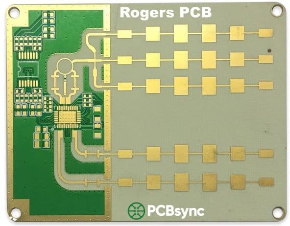
Taconic vs Rogers: Which Should You Choose?
The Taconic vs Rogers question comes up constantly in RF design. Both are quality manufacturers, but there are practical differences worth considering:
Factor
Taconic
Rogers
Cost
Generally lower, better for volume
Premium pricing
Thermal Performance
Good thermal stability
Excellent for extreme temps
Product Range
Good variety, Dk 2.17-10
Extensive range, more options
Fabrication
Standard PTFE processes
Wider fab support
Best Use Case
Cost-sensitive commercial RF
Mil/aero, complex multilayer
The bottom line: For commercial applications where cost matters and you need solid high-frequency performance, Taconic often wins on value. For aerospace, defense, or applications requiring the absolute best thermal performance, Rogers may justify the premium.
Cost Considerations and Procurement Tips
Let’s be honest—Taconic materials cost more than FR-4, typically 3-5x the base material price. But when you factor in the performance requirements, the math often works out differently than expected.
When Premium Materials Pay Off
Consider the total cost of your design. Using FR-4 for a 10 GHz application might save on material costs but lead to multiple respins when signal integrity fails. The engineering time, prototype iterations, and delayed time-to-market often exceed the material premium. For applications above 2-3 GHz, start with the right material from the beginning.
Procurement Strategies
Order material in standard panel sizes (36″x48″ common) to minimize waste
Discuss volume pricing with your fabricator for production quantities
Consider hybrid stackups to reduce Taconic usage to only RF-critical layers
Request material certifications and lot traceability for defense applications
Work with fabricators who stock Taconic materials to avoid long lead times
Additional Resources
For further technical information, consult these resources:
AGC Taconic Official Website (www.agc-multimaterial.com) – Datasheets and processing guides
IPC Standards (IPC-4101, IPC-4103) – Base material specifications
Your PCB fabricator’s engineering team – Material availability and DFM guidance
RF Cafe and Microwaves101 – Practical RF design tutorials
Frequently Asked Questions
1. What frequency range is Taconic PCB material suitable for?
Taconic materials support frequencies from 2 GHz up to 110 GHz, depending on the specific laminate. TLY-5 works well up to 77 GHz and beyond (common in automotive radar), while RF-35 is typically used up to 35 GHz. For most commercial wireless and 5G applications in the sub-6 GHz and mmWave bands, there’s a Taconic material that fits.
Yes, hybrid stackups are common and cost-effective. RF-critical layers use Taconic substrates while digital sections use standard FR-4. The key is proper bonding—work with a fabricator experienced in PTFE/epoxy hybrid lamination. Ground planes between material types help maintain isolation.
3. How does Taconic RF-35 compare to Rogers RO4350B?
Both are excellent choices for commercial RF applications with similar Dk values (RF-35: 3.5, RO4350B: 3.48). RF-35 typically costs less, making it attractive for volume production. RO4350B may have slight edges in certain thermal properties and wider fabricator support. For most designs, either will work—choose based on cost and your fab shop’s experience.
4. What special fabrication processes does Taconic require?
PTFE-based Taconic materials require plasma or sodium treatment for hole wall preparation before plating—this step is absolutely essential for reliable through-hole connections in PTFE substrates and cannot be skipped. Drilling parameters differ significantly from FR-4, requiring lower speeds and specialized carbide bits. RF-35’s woven glass reinforcement makes it more forgiving than some pure PTFE materials. Always verify your fabricator’s specific experience with PTFE processing before committing to production orders.
5. Is Taconic material suitable for lead-free assembly?
Yes. Materials like RF-35 have a Tg exceeding 315°C, well above lead-free solder reflow temperatures (typically 260°C peak). However, proper thermal relief in multilayer designs is recommended to manage stress during repeated thermal cycles. All current Taconic laminates are RoHS compliant.
Final Thoughts
Taconic PCB materials fill a critical niche in high-frequency design—providing the performance needed for RF, microwave, and mmWave applications without the cost premium of some alternatives. Whether you’re designing 5G infrastructure, automotive radar, or satellite communications systems, understanding the available material options helps you make better engineering decisions.
The RF-35 series works for most commercial applications where cost-performance balance matters. For ultra-high frequencies or extreme environments, the TLY-5 and other specialty laminates deliver the extra performance margin. And when standard FR-4 just can’t cut it anymore, Taconic materials provide a proven path to better signal integrity and reliable high-frequency operation.
Start early in your design process by engaging with your PCB fabricator about material selection—their experience with specific Taconic grades can save you significant time and money in development. Request samples for prototyping, verify fabricator certifications, and don’t hesitate to contact AGC’s technical support for application-specific guidance. The investment in proper material selection pays dividends throughout your product’s lifecycle.
Inquire: Call 0086-755-23203480, or reach out via the form below/your sales contact to discuss our design, manufacturing, and assembly capabilities.
Quote: Email your PCB files to Sales@pcbsync.com (Preferred for large files) or submit online. We will contact you promptly. Please ensure your email is correct.
Notes: For PCB fabrication, we require PCB design file in Gerber RS-274X format (most preferred), *.PCB/DDB (Protel, inform your program version) format or *.BRD (Eagle) format. For PCB assembly, we require PCB design file in above mentioned format, drilling file and BOM. Click to download BOM template To avoid file missing, please include all files into one folder and compress it into .zip or .rar format.


