Inquire: Call 0086-755-23203480, or reach out via the form below/your sales contact to discuss our design, manufacturing, and assembly capabilities.
Quote: Email your PCB files to Sales@pcbsync.com (Preferred for large files) or submit online. We will contact you promptly. Please ensure your email is correct.
Notes: For PCB fabrication, we require PCB design file in Gerber RS-274X format (most preferred), *.PCB/DDB (Protel, inform your program version) format or *.BRD (Eagle) format. For PCB assembly, we require PCB design file in above mentioned format, drilling file and BOM. Click to download BOM template To avoid file missing, please include all files into one folder and compress it into .zip or .rar format.
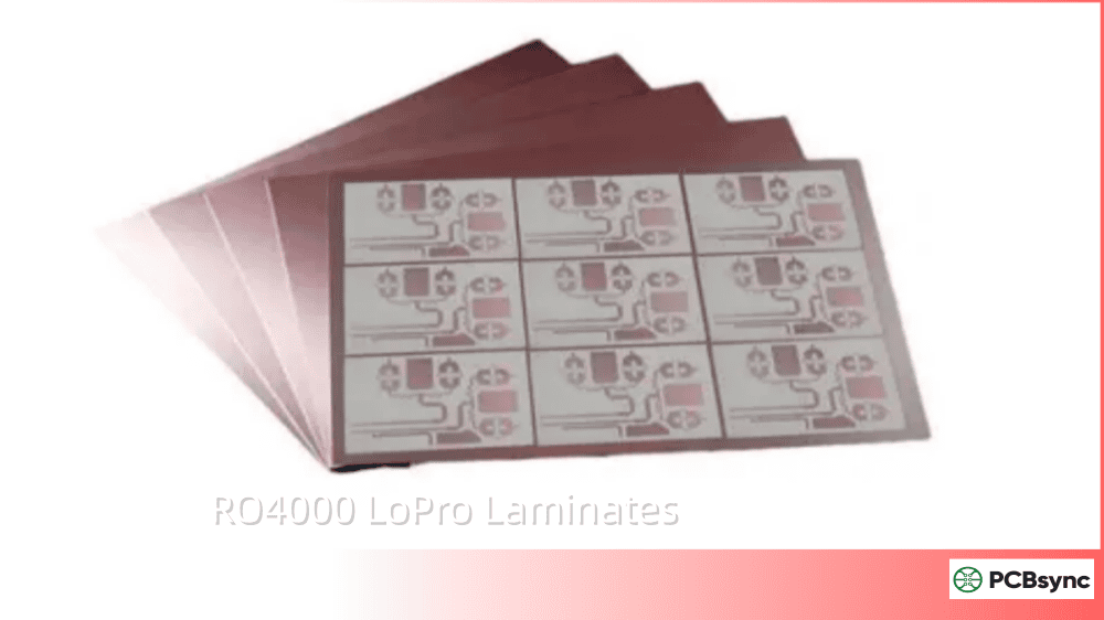
If you’ve spent any time designing high-frequency PCBs, you’ve likely run into the same frustrating tradeoff I have: you need better electrical performance, but you don’t want to deal with the headaches of PTFE processing. That’s exactly the problem RO4000 LoPro Laminates were designed to solve.
I’ve been working with Rogers materials for over a decade, and the RO4000 LoPro series has become my go-to choice for applications ranging from 5G base station antennas to automotive radar systems. In this guide, I’ll walk you through everything you need to know about these laminates—from their technical specifications to real-world fabrication tips that will save you time and money.
RO4000 LoPro Laminates are high-frequency circuit materials manufactured by Rogers Corporation. These hydrocarbon ceramic laminates combine the exceptional RF performance typically associated with PTFE materials with the ease of fabrication you get from standard FR-4 processes.
The “LoPro” designation refers to the low-profile reverse-treated copper foil that Rogers uses in these laminates. This proprietary technology allows the reverse-treated foil to bond to the standard RO4000 dielectric material, resulting in significantly reduced conductor loss compared to conventional copper-clad laminates.
How LoPro Technology Works
Here’s what makes the LoPro technology special: traditional copper foils have a rough “tooth” on the treatment side to promote adhesion to the dielectric. While this roughness improves bonding, it also increases conductor losses at high frequencies because the signal travels along the surface of the copper (skin effect).
Rogers’ LoPro technology uses a specially treated reverse-side copper foil that achieves excellent adhesion without the aggressive surface roughness. The result? You get copper peel strength equal to or better than standard RO4000 materials, but with dramatically improved insertion loss characteristics.
For double-sided boards, the LoPro foil adds approximately 0.0007″ (18μm) to the total thickness. The LoPro resin layer has a Dk of approximately 2.4, which is something you’ll need to factor into your impedance calculations.
RO4000 LoPro Laminates: Key Technical Properties
Before selecting any laminate for your design, you need to understand its electrical, thermal, and mechanical properties. Here’s a detailed breakdown of what RO4000 LoPro Laminates bring to the table.
Electrical Properties of RO4000 LoPro Laminates
The electrical performance is where RO4000 LoPro Laminates really shine. The table below summarizes the key electrical specifications:
Property
RO4003C LoPro
RO4350B LoPro
RO4835 LoPro
Test Method
Dielectric Constant (Dk) @10GHz
3.38 ±0.05
3.48 ±0.05
3.48 ±0.05
IPC-TM-650 2.5.5.5
Dissipation Factor (Df) @10GHz
0.0027
0.0037
0.0037
IPC-TM-650 2.5.5.5
Thermal Coefficient of Dk
+40 ppm/°C
+50 ppm/°C
+50 ppm/°C
IPC-TM-650 2.5.5.5
Volume Resistivity
1.7×10¹⁰ MΩ·cm
1.2×10¹⁰ MΩ·cm
1.7×10¹⁰ MΩ·cm
IPC-TM-650 2.5.17.1
Surface Resistivity
4.2×10⁹ MΩ
5.7×10⁹ MΩ
4.2×10⁹ MΩ
IPC-TM-650 2.5.17.1
A few things worth noting: The design Dk values represent averages from multiple tested lots. In practice, the Dk decreases by about 0.1 as core thickness drops from 0.020″ to 0.004″. This is critical information for your impedance calculations—always use the design Dk specific to your chosen thickness.
Thermal and Mechanical Properties
High-frequency circuits often generate significant heat, making thermal properties just as important as electrical ones. RO4000 LoPro Laminates excel in this area:
Property
Value
Test Method
Glass Transition Temperature (Tg)
>280°C (536°F)
IPC-TM-650 2.4.25 (TMA)
CTE (X-axis)
10-12 ppm/°C
IPC-TM-650 2.4.41
CTE (Y-axis)
14-16 ppm/°C
IPC-TM-650 2.4.41
CTE (Z-axis) below Tg
32 ppm/°C
IPC-TM-650 2.4.41
Thermal Conductivity
0.62-0.71 W/m·K
ASTM E1530
Td (Decomposition Temperature)
390°C (734°F)
TGA
Moisture Absorption
0.06%
IPC-TM-650 2.6.2.1
That high Tg of over 280°C is particularly valuable—it means the expansion characteristics remain stable across the entire range of circuit processing temperatures, including lead-free assembly cycles.
Mechanical Strength and Copper Adhesion
One concern engineers often have with low-profile copper is whether it compromises peel strength. With RO4000 LoPro Laminates, that’s not an issue:
Property
Typical Value
Test Condition
Peel Strength (1 oz copper)
6 lb/in (1.05 N/mm)
After solder float
Peel Strength (After Thermal Stress)
5.5 lb/in (0.96 N/mm)
288°C, 10 sec
Flexural Strength (MD)
45 ksi (310 MPa)
IPC-TM-650 2.4.4
Flexural Modulus
2900 ksi (20 GPa)
IPC-TM-650 2.4.4
The copper peel strength equals or exceeds that of standard RO4000 materials, which means you’re not sacrificing mechanical reliability for electrical performance.
Benefits of RO4000 LoPro Laminates for High-Frequency Design
When I’m evaluating materials for a high-frequency project, I look at several key performance factors. Here’s why RO4000 LoPro Laminates consistently make my shortlist.
Lower Insertion Loss for Better Signal Integrity
Insertion loss is the enemy of high-frequency design. Every dB of loss means reduced signal strength, degraded signal-to-noise ratio, and potentially compromised system performance.
RO4000 LoPro Laminates achieve insertion loss as low as 1.3 dB/inch at certain frequencies—a significant improvement over standard copper-clad laminates. This improvement comes from two sources: the low dissipation factor of the dielectric and, more importantly, the reduced conductor loss from the low-profile copper.
In practical terms, this means you can design circuits operating at frequencies above 40 GHz without the signal degradation that would make standard materials unsuitable.
If you’re designing base station antennas or any high-power RF system, PIM is likely keeping you up at night. Passive intermodulation occurs when two or more signals mix at a nonlinear junction, creating unwanted intermodulation products that can fall directly into your receive band.
RO4000 LoPro Laminates were specifically engineered to minimize PIM. The low-profile copper surface reduces the nonlinearities that generate PIM products, making these materials ideal for cellular infrastructure and other applications where spectral purity is critical.
FR-4 Compatible Processing
Here’s where RO4000 LoPro Laminates really stand out from PTFE alternatives: you can fabricate them using standard epoxy/glass processes. No sodium etch required for via preparation. No special handling procedures. Your existing FR-4 fabrication line can handle these materials with minimal adjustment.
This compatibility translates directly to lower manufacturing costs and faster turnaround times—often 30-50% less than comparable PTFE-based solutions.
Lead-Free Assembly Compatible
With RoHS compliance now standard, lead-free compatibility isn’t optional. The high Tg (>280°C) of RO4000 LoPro Laminates ensures they can withstand the higher temperatures of lead-free soldering processes without degradation.
For Rogers PCB applications requiring UL 94 V-0 flame retardancy, the RO4350B LoPro variant meets this requirement, though note that RO4350B LoPro has a separate UL designation from standard RO4350B laminates.
RO4000 LoPro Laminates Variants Comparison
Rogers offers several variants within the RO4000 LoPro family. Choosing the right one depends on your specific application requirements.
Available RO4000 LoPro Variants
Variant
Dk @10GHz
Df @10GHz
Key Features
Primary Applications
RO4003C LoPro
3.38 ±0.05
0.0027
Lowest loss, non-flame retardant
RF modules, LNBs, low-loss RF
RO4350B LoPro
3.48 ±0.05
0.0037
UL 94 V-0, tight Dk control
Base station antennas, power amps
RO4835 LoPro
3.48 ±0.05
0.0037
10x oxidation resistance, spread glass
Automotive radar, mmWave
RO4835IND LoPro
3.48 @60GHz
0.0037
Industrial radar optimized
60-81 GHz industrial radar
RO4003C LoPro vs RO4350B LoPro: Which One to Choose?
This is the most common question I get, so let me break it down simply:
Choose RO4003C LoPro when:
You need the absolute lowest dielectric loss
Flame retardancy isn’t required
You’re designing low-noise amplifiers or receiver front ends
Cost is a primary concern (RO4003C is generally less expensive)
Choose RO4350B LoPro when:
You need UL 94 V-0 flame retardancy
You’re designing power amplifiers or active devices
The application requires stringent safety certifications
You’re working on base station antennas
RO4835 LoPro for Automotive and Industrial Applications
The RO4835 LoPro variant deserves special mention for automotive radar applications. With 10x the oxidation resistance of traditional thermoset laminates and spread glass construction to minimize Dk variation, it’s specifically optimized for the harsh temperature cycling and long service life requirements of automotive electronics.
For industrial radar sensors operating in the 60-81 GHz range, the RO4835IND LoPro offers a design Dk of 3.48 at 60 GHz and 3.49 at 77 GHz—ensuring consistent performance at millimeter-wave frequencies.
Applications of RO4000 LoPro Laminates
The versatility of RO4000 LoPro Laminates makes them suitable for a wide range of high-frequency applications. Here are the primary markets where these materials excel.
5G and Cellular Base Station Antennas
Base station antennas represent one of the largest markets for RO4000 LoPro Laminates. The combination of low insertion loss, excellent PIM performance, and UL 94 V-0 flame retardancy (with RO4350B LoPro) makes these materials ideal for massive MIMO antenna arrays and other 5G infrastructure.
The low-profile copper is particularly valuable here—at the high power levels used in base stations, even small nonlinearities can generate significant PIM products that interfere with received signals.
Automotive Radar (ADAS, 77 GHz)
Advanced Driver Assistance Systems rely on 77 GHz radar sensors for functions like adaptive cruise control, collision avoidance, and blind-spot detection. RO4000 LoPro Laminates—particularly the RO4835 variant—offer the combination of millimeter-wave performance and automotive-grade reliability these applications demand.
The spread glass construction in RO4835 LoPro minimizes Dk variation across the panel, which is critical for achieving consistent phase and amplitude performance in radar antenna arrays.
High-Speed Digital Backplanes
It’s not just RF engineers who benefit from RO4000 LoPro Laminates. As data rates push into the multi-gigabit range, signal integrity challenges that were once exclusive to RF design now affect digital systems as well.
For high-speed backplanes running at 56 Gbps NRZ and beyond, hybrid stackups combining RO4000 LoPro cores for critical high-speed layers with standard FR-4 for power distribution offer an excellent balance of performance and cost.
Additional Applications
RO4000 LoPro Laminates are also widely used in:
Direct broadcast satellite LNBs
Microwave radio links
Automatic test equipment (ATE)
Servers and high-speed routers
Aerospace and defense RF systems
RFID readers and systems
PCB Fabrication Guidelines for RO4000 LoPro Laminates
One of the biggest advantages of RO4000 LoPro Laminates is their compatibility with standard FR-4 fabrication processes. However, there are some specific guidelines that will help ensure optimal results.
Storage and Handling Requirements
Proper material handling starts before fabrication begins:
Parameter
Requirement
Storage Temperature
20°C to 25°C (68°F to 77°F)
Relative Humidity
40% to 60%
Acclimatization
24 hours at room temperature before processing
Handling
Clean, lint-free gloves; avoid bending or folding
Unlike some high-frequency materials, RO4000 LoPro Laminates can be stored indefinitely under ambient conditions. The dielectric materials are inert to high humidity at room temperature, though copper oxidation can occur during prolonged exposure to humid conditions.
Drilling and Routing Parameters
RO4000 LoPro Laminates machine well with standard carbide tooling:
Process
Recommended Parameters
Drill Speed
150-300 surface meters per minute
Chip Load
0.05-0.10 mm/revolution
Router Speed
200-300 surface meters per minute
Feed Rate
1.5-3 meters per minute
Stack Height
70% of flute length maximum
Use sharp, high-quality drill bits designed for FR-4 materials. Tool life is generally greater than 50 linear feet when following these parameters. The low Z-axis thermal expansion of these materials also supports longer drill tool life compared to some alternatives.
Lamination Process for Multilayer Boards
For multilayer constructions using RO4450B or RO4450F bondply:
Parameter
Recommended Value
Lamination Temperature
182°C to 199°C (360°F to 390°F)
Lamination Pressure
200-350 PSI (14-24 kg/cm²)
Heating Rate
3°C to 5°C per minute
Cooling Rate
3°C to 5°C per minute
Minimum Dwell at Cure Temp
60 minutes
Apply pressure before the package temperature exceeds 38°C (100°F). For high layer count designs or those with buried metal layers thicker than ½ oz copper, higher pressures (650-750 PSI) may be necessary.
Desmear and Plating Considerations
While RO4000 LoPro Laminates don’t require sodium etch like PTFE materials, multilayer constructions will need desmear. Both CF4/O2 plasma and alkaline-permanganate processes work well.
For electroless copper deposition and plating:
Use standard FR-4 processes
Optimize pre-treatment steps for proper adhesion
Maintain uniform current distribution during plating
Surface Finish Compatibility
RO4000 LoPro Laminates are compatible with common surface finishes:
ENIG (Electroless Nickel Immersion Gold)
HASL (Hot Air Solder Leveling)
OSP (Organic Solderability Preservatives)
Immersion Silver
Immersion Tin
RO4000 LoPro Laminates vs Standard RO4000: Direct Comparison
Understanding the differences between LoPro and standard variants helps you make informed material selections:
Parameter
RO4350B Standard
RO4350B LoPro
Improvement
Copper Surface Roughness
Standard ED
Low-profile RT
~50% reduction
Insertion Loss @10GHz
Higher
Lower
~15-25% improvement
PIM Performance
Good
Excellent
Significant improvement
Copper Peel Strength
6 lb/in
6 lb/in
Equivalent
Processing Compatibility
FR-4
FR-4
Equivalent
Core Thickness (with foil)
Standard
+0.0007″
Slight increase
The key takeaway: you get better electrical performance without sacrificing mechanical reliability or process compatibility.
RO4000 LoPro Laminates vs PTFE Materials
For engineers considering PTFE-based alternatives, here’s how RO4000 LoPro compares:
Factor
RO4000 LoPro
PTFE (e.g., RT/duroid)
Electrical Performance
Excellent (Dk 3.38-3.48)
Excellent (Dk 2.2-10.2)
Insertion Loss
Very Low
Very Low
Processing
Standard FR-4
Specialized (sodium etch)
Fabrication Cost
Lower
Higher
Dimensional Stability
Excellent
Good (PTFE is soft)
PTH Reliability
Excellent
Requires special treatment
CAF Resistance
Yes
Varies
RO4000 LoPro Laminates offer “PTFE-like” performance with “FR-4-like” processing—the best of both worlds for many applications.
Real-World Performance: Case Studies
To illustrate the practical benefits of RO4000 LoPro Laminates, let me share two examples from projects I’ve been involved with.
Case Study 1: 5G Base Station Feed Network
A telecommunications equipment manufacturer was developing 28 GHz antenna feed networks for 5G base stations. Their initial design using standard FR-4 was experiencing unacceptable insertion loss—about 0.8 dB higher than the link budget allowed.
By switching to RO4003C LoPro for the feed network layers while keeping FR-4 for power distribution, they achieved:
23% reduction in insertion loss
PIM levels improved by 8 dB
Total material cost increase of only 15% due to hybrid stackup approach
The project met all performance targets and entered production successfully.
Case Study 2: 56 Gbps Digital Backplane
A data center equipment company needed to support 56 Gbps NRZ signaling over 20-inch backplane traces. Standard FR-4 was causing excessive eye closure at the receiver.
Their solution involved implementing RO4003C LoPro for the high-speed differential pairs with the following results:
Eye height improved from 45 mV to 72 mV
BER improved from 10⁻⁹ to 10⁻¹² at target margins
Manufacturing yields improved due to wider process windows
These examples demonstrate that the benefits of RO4000 LoPro extend well beyond traditional RF applications into high-speed digital design.
How to Select the Right RO4000 LoPro Variant
Selecting the optimal variant requires balancing several factors. Here’s my decision framework:
Account for the LoPro resin layer (Dk ≈ 2.4) in thickness calculations
The Dk decreases by ~0.1 as thickness drops from 0.020″ to 0.004″
Run first articles to establish scaling factors before production
Most EDA tools allow you to define custom stackups with accurate material properties. Don’t rely on generic “Rogers” settings—input the actual design Dk from the datasheet.
Thermal Management Strategies
While RO4000 LoPro Laminates have moderate thermal conductivity (0.62-0.71 W/m·K), proper thermal design is still essential for high-power applications:
Use thermal vias beneath power components
Consider copper pours on inner layers for heat spreading
The matched CTE to copper reduces thermal stress on solder joints
Artwork Compensation
Compensate for thermal expansion and contraction in your artwork. Use the CTE values from the datasheet, and work with your fabricator to establish appropriate scaling factors.
Hybrid Stackup Design
For cost-sensitive designs, consider hybrid stackups:
Use RO4000 LoPro for high-speed/RF signal layers
Use standard FR-4 for power and low-speed signal layers
RO4450 bondply enables bonding RO4000 cores to FR-4
This approach can reduce material costs by 30-50% while maintaining performance where it matters.
Useful Resources for RO4000 LoPro Laminates
Here are the essential resources for working with these materials:
Rogers Technology Support Hub: Calculators, technical papers, and design tools
Local Sales Representatives: Contact for application-specific guidance
Customer Service: For product availability and custom configurations
Industry Standards
IPC-4103: Specification for base materials for high-frequency PCBs
IPC-TM-650: Test methods referenced in Rogers datasheets
Frequently Asked Questions About RO4000 LoPro Laminates
Is RO4000 LoPro compatible with lead-free assembly?
Yes, absolutely. With a glass transition temperature exceeding 280°C, RO4000 LoPro Laminates are fully compatible with lead-free soldering processes. The high Tg ensures the material’s expansion characteristics remain stable throughout the assembly process. The materials are also RoHS compliant.
What is the Dk (dielectric constant) of RO4000 LoPro?
It depends on the specific variant. RO4003C LoPro has a design Dk of 3.38 ±0.05 at 10 GHz, while RO4350B LoPro and RO4835 LoPro both have a design Dk of 3.48 ±0.05 at 10 GHz. Keep in mind that the LoPro resin layer has a Dk of approximately 2.4, which affects the overall effective Dk, particularly for thinner cores.
Can I use standard FR-4 processes to fabricate RO4000 LoPro boards?
Yes, this is one of the primary advantages of RO4000 LoPro Laminates. Unlike PTFE materials that require sodium etch and special handling, RO4000 LoPro can be processed using standard epoxy/glass fabrication techniques. This includes drilling, routing, plating, and assembly. The only adjustment needed is using appropriate desmear processes for multilayer constructions.
What’s the maximum operating frequency for RO4000 LoPro Laminates?
RO4000 LoPro Laminates support designs operating at frequencies well above 40 GHz. The RO4835IND LoPro variant is specifically characterized for 60-81 GHz industrial radar applications. For millimeter-wave applications, the low insertion loss and tight Dk control make these materials excellent choices.
How does RO4000 LoPro compare to RO4835 for automotive radar?
RO4835 (and RO4835 LoPro) is specifically optimized for automotive applications with 10x the oxidation resistance of traditional thermoset laminates and spread glass construction for better Dk uniformity. If you’re designing for automotive radar, RO4835 LoPro is generally the better choice. For non-automotive applications where maximum oxidation resistance isn’t critical, standard RO4350B LoPro may be more cost-effective while still delivering excellent performance.
Conclusion
RO4000 LoPro Laminates represent a significant advancement in high-frequency PCB materials. By combining the electrical performance typically associated with PTFE substrates with the processing simplicity of FR-4, Rogers has created materials that serve an increasingly demanding range of applications—from 5G infrastructure to automotive radar to high-speed digital systems.
The key advantages are clear: lower insertion loss for improved signal integrity, excellent PIM performance for antenna applications, FR-4-compatible processing for cost efficiency, and robust thermal properties for lead-free assembly compatibility.
Whether you’re an RF engineer pushing into millimeter-wave frequencies or a digital designer dealing with multi-gigabit signal integrity challenges, RO4000 LoPro Laminates deserve serious consideration for your next high-performance design.
For specific application guidance or to request material samples, I recommend reaching out to Rogers Corporation directly or consulting with your PCB fabricator about their experience with these materials.
Inquire: Call 0086-755-23203480, or reach out via the form below/your sales contact to discuss our design, manufacturing, and assembly capabilities.
Quote: Email your PCB files to Sales@pcbsync.com (Preferred for large files) or submit online. We will contact you promptly. Please ensure your email is correct.
Notes: For PCB fabrication, we require PCB design file in Gerber RS-274X format (most preferred), *.PCB/DDB (Protel, inform your program version) format or *.BRD (Eagle) format. For PCB assembly, we require PCB design file in above mentioned format, drilling file and BOM. Click to download BOM template To avoid file missing, please include all files into one folder and compress it into .zip or .rar format.


