Inquire: Call 0086-755-23203480, or reach out via the form below/your sales contact to discuss our design, manufacturing, and assembly capabilities.
Quote: Email your PCB files to Sales@pcbsync.com (Preferred for large files) or submit online. We will contact you promptly. Please ensure your email is correct.
Notes: For PCB fabrication, we require PCB design file in Gerber RS-274X format (most preferred), *.PCB/DDB (Protel, inform your program version) format or *.BRD (Eagle) format. For PCB assembly, we require PCB design file in above mentioned format, drilling file and BOM. Click to download BOM template To avoid file missing, please include all files into one folder and compress it into .zip or .rar format.
If you’re designing RF circuits for 5G, automotive radar, or satellite systems, you’ve probably hit the wall with standard FR-4. The signal losses above 10 GHz become unacceptable, the dielectric constant drifts with temperature, and suddenly your carefully simulated impedance is nowhere close to what you measured on the bench.
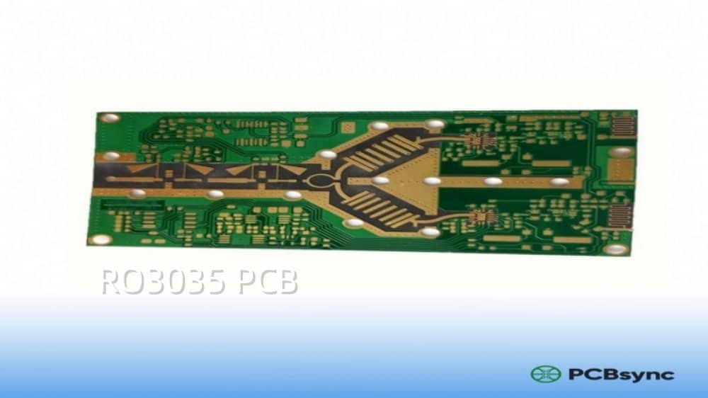
That’s exactly where RO3035 PCB material comes in. As a ceramic-filled PTFE laminate from Rogers Corporation, RO3035 delivers the electrical stability and low-loss performance that high-frequency designs demand. I’ve worked with this material on several mmWave projects, and once you understand its strengths and quirks, it becomes an incredibly reliable substrate for demanding applications.
In this guide, I’ll walk you through everything you need to know about RO3035 — from its technical specifications to practical design tips that will save you headaches during fabrication.
RO3035 is a high-frequency laminate belonging to the RO3000 series from Rogers Corporation. It’s a ceramic-filled PTFE (polytetrafluoroethylene) composite specifically engineered for commercial microwave and RF applications.
Unlike woven-glass reinforced materials, RO3035 doesn’t contain fiberglass. This absence of glass cloth gives it isotropic electrical properties — meaning the dielectric constant remains consistent regardless of the signal direction. For anyone who’s dealt with the anisotropic behavior of glass-reinforced laminates at high frequencies, this is a significant advantage.
The material sits within a family that includes RO3003, RO3006, and RO3010, each offering different dielectric constants while maintaining identical mechanical properties. This consistency allows designers to create multilayer stackups using different Dk values per layer without worrying about CTE mismatch or warpage issues.
Why Engineers Choose RO3035 PCB Over Standard Materials
The primary reasons come down to three factors:
Signal Integrity at High Frequencies Standard FR-4 starts showing significant losses above 1-2 GHz. The dissipation factor (Df) of FR-4 typically ranges from 0.020 to 0.025, while RO3035 delivers a Df of just 0.0015 to 0.0017 at 10 GHz. That’s more than a 10x improvement in signal loss characteristics.
Temperature Stability The dielectric constant of RO3035 remains remarkably stable across a wide temperature range. Where FR-4’s Dk can vary by several percent over operating temperatures, RO3035 maintains tight control — critical for phase-sensitive applications like phased array antennas.
Matched Thermal Expansion RO3035’s CTE of 17 ppm/°C in X and Y axes matches copper exactly. This prevents the stress-related failures you’d see with materials that expand at different rates during thermal cycling.
RO3035 PCB Technical Specifications
Understanding the specs is crucial before committing to any material. Here’s the complete specification breakdown for RO3035:
Electrical Properties
Property
Value
Test Condition
Dielectric Constant (Dk)
3.50 ± 0.05
10 GHz / 23°C
Design Dk
3.50
Process recommendation
Dissipation Factor (Df)
0.0015 – 0.0017
10 GHz / 23°C
Volume Resistivity
10⁷ MΩ·cm
Condition A
Surface Resistivity
10⁷ MΩ
Condition A
Electrical Strength
31 kV/mm
—
Thermal Properties
Property
Value
Notes
Thermal Conductivity
0.50 W/m·K
—
CTE (X-axis)
17 ppm/°C
-55°C to 288°C
CTE (Y-axis)
17 ppm/°C
-55°C to 288°C
CTE (Z-axis)
24 ppm/°C
-55°C to 288°C
Td (Decomposition Temperature)
>500°C
TGA
TCDk (Thermal Coefficient of Dk)
15 ppm/°C
—
Mechanical Properties
Property
Value
Test Method
Peel Strength
8.9 lb/in (1.56 N/mm)
1 oz EDC foil
Flexural Strength
—
Inherently flexible
Density
2.1 g/cm³
—
Moisture Absorption
0.05%
48 hr immersion
Flammability
V-0
UL 94
Available Thicknesses and Copper Options
Substrate Thickness
Tolerance
0.005″ (0.13 mm)
± 0.0005″
0.010″ (0.25 mm)
± 0.0007″
0.020″ (0.50 mm)
± 0.0010″
0.030″ (0.76 mm)
± 0.0015″
0.060″ (1.52 mm)
± 0.0020″
Copper Foil Options:
½ oz (18 μm) Electrodeposited
1 oz (35 μm) Electrodeposited
Rolled Copper (for ultra-low insertion loss)
Standard Panel Sizes:
12″ × 18″ (305 × 457 mm)
24″ × 18″ (610 × 457 mm)
Key Benefits of RO3035 PCB for High-Frequency Design
Let me break down the practical advantages that matter most when you’re actually designing circuits.
Ultra-Low Dielectric Loss
At 77 GHz, RO3035’s dissipation factor remains around 0.0019. This is exceptional for automotive radar and mmWave 5G applications where every fraction of a dB matters. Lower loss means better receiver sensitivity, longer range, and more efficient power amplifier designs.
Excellent Dimensional Stability
The material exhibits less than 0.5 mils per inch etch shrinkage after processing. This predictability simplifies impedance calculations and reduces the need for costly design iterations. When you’re working with 50-ohm microstrip lines at 77 GHz, trace width tolerances of a few microns can make or break your design.
Consistent Performance Across Frequencies
Unlike some materials that show significant Dk variation with frequency, RO3035 maintains consistent behavior from DC through 40+ GHz. The frequency dependence curves show minimal slope, which simplifies broadband design work.
Superior PTH Reliability
The Z-axis CTE of 24 ppm/°C is significantly better than FR-4’s typical 60+ ppm/°C. This translates directly to improved plated through-hole (PTH) reliability, especially important for multilayer boards subjected to thermal cycling.
Hybrid Stackup Compatibility
RO3035 can be combined with FR-4 in hybrid constructions, placing the RF circuits on RO3035 layers while using standard FR-4 for digital/control sections. This approach balances performance with cost-effectiveness.Read more Rogers PCBs:
RO3035 PCB Applications: Where This Material Excels
Based on the material properties, certain applications benefit most from RO3035’s characteristics.
5G Infrastructure and Millimeter Wave Systems
5G base stations operating in sub-6 GHz and mmWave bands (24-39 GHz) require substrates that can handle high frequencies with minimal signal degradation. RO3035 PCB supports these designs with its stable Dk and low loss tangent. Massive MIMO antenna arrays particularly benefit from the phase consistency this material provides.
Automotive Radar Systems (77 GHz)
Modern vehicles use 77 GHz radar for adaptive cruise control, collision avoidance, and autonomous driving functions. At these frequencies, material selection directly impacts detection range and accuracy. RO3035’s performance at 77 GHz — with Df values around 0.0019 — makes it suitable for these safety-critical applications.
Satellite Communications
Low-noise block downconverters (LNBs), feed networks, and satellite antenna systems demand materials with tight impedance control. Ka-band applications (26.5-40 GHz) particularly benefit from RO3035’s stability across temperature extremes encountered in outdoor installations.
Wireless Communication Patch Antennas
Patch antenna designs require predictable dielectric properties for accurate radiation pattern control. The isotropic nature of RO3035 (no glass reinforcement) eliminates the directional variations that complicate antenna design with woven-glass materials.
Power Amplifiers
High-power RF amplifiers generate significant heat. RO3035’s thermal conductivity of 0.5 W/m·K, combined with its temperature-stable Dk, helps maintain performance even under demanding thermal conditions.
Additional Applications
Global positioning satellite (GPS) antennas
Direct broadcast satellite systems
Datalink systems for cable networks
Remote meter reading systems
Point-to-point microwave backhaul
Medical imaging equipment
RO3035 vs Other High-Frequency Materials: Comparison Guide
Choosing between Rogers materials depends on your specific requirements. Here’s how RO3035 stacks up against common alternatives.
RO3035 vs RO3003
Parameter
RO3035
RO3003
Dielectric Constant (Dk)
3.50 ± 0.05
3.00 ± 0.04
Dissipation Factor (Df)
0.0015
0.0013
Best For
General RF, balanced impedance
Lowest loss, 77 GHz radar
Cost
Moderate
Moderate
When to Choose RO3003: If you need the absolute lowest insertion loss and your impedance requirements can work with Dk = 3.0.
When to Choose RO3035: When you need slightly higher Dk for narrower trace widths or tighter impedance matching.
RO3035 vs RO4350B
Parameter
RO3035
RO4350B
Dielectric Constant (Dk)
3.50 ± 0.05
3.48 ± 0.05
Dissipation Factor (Df)
0.0015
0.0037
Material Base
Ceramic-filled PTFE
Hydrocarbon ceramic
Processing
Requires PTFE handling
FR-4 compatible
Cost
Higher
Lower
Frequency Range
Up to 77 GHz+
Up to 10-20 GHz
When to Choose RO4350B: For applications below 10 GHz where you want simpler fabrication and lower material cost. It processes like FR-4, which most fab shops can handle without specialized equipment.
When to Choose RO3035: For applications above 20 GHz, or when the lowest possible loss is critical to your design margins.
RO3035 vs Standard FR-4
Parameter
RO3035
Standard FR-4
Dielectric Constant (Dk)
3.50
4.2-4.8
Dissipation Factor (Df)
0.0015
0.020-0.025
Dk Stability vs Temp
Excellent
Poor
Dk Stability vs Freq
Excellent
Poor
Maximum Useful Frequency
77 GHz+
~1-2 GHz
Cost
10-20x higher
Baseline
FR-4 remains the practical choice for digital circuits and low-frequency analog work. But for anything above a few GHz, the performance gap becomes significant.
RO3035 PCB Design Guidelines
Getting the most out of RO3035 requires attention to several design factors.
Impedance Control Considerations
Use the design Dk value of 3.50 for impedance calculations. Rogers provides this value specifically for design purposes, accounting for typical processing conditions. For tighter control, request Dk tolerance data for your specific thickness and work with your fabricator to establish process Dk values.
Typical 50-ohm microstrip width on 10 mil RO3035 is approximately 25 mils — significantly narrower than on FR-4, which can be advantageous for dense layouts.
Transmission Line Design
Microstrip: RO3035 works well for microstrip designs. The smooth surface (especially with rolled copper foil) minimizes conductor losses from skin effect at high frequencies.
Stripline: For better isolation and lower radiation, stripline configurations are straightforward since RO3000 series materials can be combined in multilayer stackups without mechanical compatibility issues.
Grounded Coplanar Waveguide (GCPW): This topology provides good isolation and works well on RO3035. Maintain gap-to-trace ratios that optimize your target impedance.
Via Design for High-Frequency Performance
Use smaller via diameters when possible (8-10 mil) to minimize inductance
Backdrilled vias improve performance by removing unused via stubs
Via fencing around transmission lines helps contain fields and reduce crosstalk
Thermal vias under power devices should connect directly to ground planes
Layer Stackup Recommendations
For hybrid designs combining RO3035 with FR-4:
Layer
Material
Purpose
Top
RO3035
RF circuits
Prepreg
RO3003 bondply
Bonding
Inner 1
FR-4
Ground plane
Core
FR-4
Digital/control
Inner 2
FR-4
Power plane
Prepreg
Standard
Bonding
Bottom
FR-4
Digital routing
This approach concentrates the more expensive material where it’s needed while keeping costs reasonable for non-RF sections.
RO3035 PCB Manufacturing and Processing Tips
PTFE-based materials require specialized handling compared to FR-4. Understanding these requirements helps you communicate effectively with your fabricator and avoid processing issues.
Drilling Considerations
Use sharp carbide bits with appropriate rake angles for PTFE
Slower feed rates than FR-4 to prevent material smearing
Entry and exit materials specifically designed for PTFE help maintain hole quality
PTFE’s chemical inertness requires surface treatment before copper plating:
Plasma etching or sodium naphthalene treatment creates a bondable surface
This step is critical — skip it and your plating will fail during thermal cycling
Not all fab shops have these capabilities, so verify before placing orders
Lamination Parameters
Parameter
Typical Range
Temperature
200-220°C
Pressure
Carefully controlled (PTFE flows under pressure)
Ramp Rate
Slow (2-3°C/min)
Cool Down
Controlled to minimize stress
Excessive pressure causes PTFE to flow, changing dielectric thickness. This is why working with experienced Rogers PCB fabricators matters — they understand these sensitivities.
Surface Finish Options
Finish
Suitability for RO3035
ENIG
Good, commonly used
Immersion Gold
Excellent for wire bonding
OSP
Limited shelf life
Immersion Silver
Good for soldering
ENEPIG
Best for mixed assembly
ENIG (Electroless Nickel Immersion Gold) is the most common choice, providing good solderability and wire bondability.
Cost Considerations and Sourcing RO3035
Let’s address the elephant in the room: RO3035 isn’t cheap. Raw laminate costs range from $100 to $600 per sheet depending on thickness, copper weight, and panel size. That’s 10-20 times more expensive than FR-4.
Factors Affecting RO3035 PCB Price
Factor
Impact on Cost
Substrate thickness
Thicker = more expensive
Copper weight
Heavier copper = higher cost
Panel utilization
Better nesting = lower per-board cost
Volume
Higher quantities reduce unit cost
Layer count
Each RO3035 layer adds significant cost
Processing complexity
PTFE handling premiums
Cost Optimization Strategies
Hybrid Stackups: Use RO3035 only where RF performance demands it. Route digital signals on FR-4 layers.
Panel Optimization: Work with your fab shop to maximize the number of boards per panel.
Standardize Thicknesses: Using common thicknesses (10 mil, 20 mil) typically costs less than custom options.
Volume Commitments: If you have ongoing production needs, negotiate volume pricing with distributors.
Authorized Distributors
Rogers materials are available through authorized distribution partners including:
Digi-Key Electronics
Mouser Electronics
Richardson Electronics
Arrow Electronics
Lead times vary from stock availability to 8-12 weeks for non-standard configurations.
Useful Resources for RO3035 PCB Design
Official Documentation
Resource
Description
Link
RO3000 Series Datasheet
Complete specifications for RO3003, RO3006, RO3010, RO3035
These are available through the Rogers Technology Support Hub.
Frequently Asked Questions About RO3035 PCB
What frequency range is RO3035 suitable for?
RO3035 PCB material performs well from DC through 77 GHz and beyond. The low dissipation factor (0.0015-0.0019) maintains signal integrity at millimeter-wave frequencies. Most practical applications fall in the 1-77 GHz range, covering 5G, automotive radar, satellite, and general RF work.
Can RO3035 be used in multilayer PCBs?
Yes, RO3035 works well in multilayer constructions. The RO3000 series shares identical mechanical properties regardless of Dk value, so you can combine RO3035 with RO3003 or RO3006 layers without CTE mismatch issues. Hybrid stackups with FR-4 are also possible using appropriate bonding materials.
Is RO3035 RoHS compliant?
Yes, Rogers RO3035 laminates comply with RoHS (Restriction of Hazardous Substances) requirements. The material is also compatible with lead-free soldering processes, with thermal stability exceeding 500°C decomposition temperature.
What’s the main difference between RO3035 and FR-4?
The differences are substantial. RO3035 has a dissipation factor of 0.0015 compared to FR-4’s 0.020-0.025 — more than 10x lower loss. RO3035’s Dk remains stable across temperature and frequency, while FR-4 varies significantly. RO3035’s CTE matches copper (17 ppm/°C), preventing thermal stress. However, FR-4 costs 10-20x less and is suitable for applications below 1-2 GHz.
How much does RO3035 PCB fabrication cost?
Raw RO3035 laminate costs $100-600 per sheet. Finished PCB costs depend on layer count, board size, and complexity. Expect 3-5x the cost of equivalent FR-4 boards for simple 2-layer designs, increasing for multilayer constructions. Hybrid stackups with FR-4 can reduce costs while maintaining RF performance where needed.
Conclusion
RO3035 PCB material delivers the electrical performance that modern RF and microwave designs demand. Its combination of low dielectric loss, stable Dk across temperature and frequency, and matched CTE with copper makes it a reliable choice for applications from 5G base stations to 77 GHz automotive radar.
The material isn’t for every application — for digital circuits or low-frequency work, FR-4 remains the practical choice. But when your design pushes into the microwave and millimeter-wave spectrum, RO3035 provides the foundation for successful, manufacturable circuits.
Work with fabricators experienced in PTFE processing, use the design Dk values Rogers provides, and optimize your stackup to balance performance with cost. With the right approach, RO3035 enables designs that simply aren’t possible with standard materials.
Inquire: Call 0086-755-23203480, or reach out via the form below/your sales contact to discuss our design, manufacturing, and assembly capabilities.
Quote: Email your PCB files to Sales@pcbsync.com (Preferred for large files) or submit online. We will contact you promptly. Please ensure your email is correct.
Notes: For PCB fabrication, we require PCB design file in Gerber RS-274X format (most preferred), *.PCB/DDB (Protel, inform your program version) format or *.BRD (Eagle) format. For PCB assembly, we require PCB design file in above mentioned format, drilling file and BOM. Click to download BOM template To avoid file missing, please include all files into one folder and compress it into .zip or .rar format.


