Inquire: Call 0086-755-23203480, or reach out via the form below/your sales contact to discuss our design, manufacturing, and assembly capabilities.
Quote: Email your PCB files to Sales@pcbsync.com (Preferred for large files) or submit online. We will contact you promptly. Please ensure your email is correct.
Notes: For PCB fabrication, we require PCB design file in Gerber RS-274X format (most preferred), *.PCB/DDB (Protel, inform your program version) format or *.BRD (Eagle) format. For PCB assembly, we require PCB design file in above mentioned format, drilling file and BOM. Click to download BOM template To avoid file missing, please include all files into one folder and compress it into .zip or .rar format.
Raspberry Pi GPIO Pinout Explained: The Complete Reference Guide
Every engineer who works with Raspberry Pi eventually faces the same challenge: staring at that 40-pin header wondering which pins do what. After spending years designing embedded systems and prototyping countless Pi-based projects, I’ve learned that understanding the raspberry pi pinout isn’t just about memorizing numbers. It’s about knowing how to leverage each pin’s capabilities without frying your board.
This guide breaks down every aspect of the GPIO pins on modern Raspberry Pi models. Whether you’re connecting your first LED or designing a complex sensor array, this reference will become your go-to resource for working with raspberry pi pins.
GPIO stands for General Purpose Input/Output. These pins form the physical interface between your Raspberry Pi and the outside world. Unlike dedicated pins on microcontrollers, GPIO pins can be configured through software as either inputs or outputs, giving you flexibility in how you interact with external hardware.
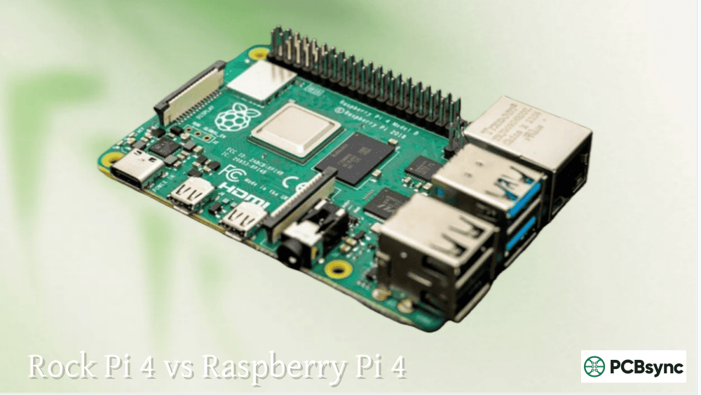
The 40-pin header found on Raspberry Pi models from the B+ onwards provides 26 configurable GPIO pins, power outputs, ground connections, and specialized communication interfaces. This standardized layout means HATs (Hardware Attached on Top) and breakout boards designed for one Pi model typically work across the entire modern lineup.
What makes the raspberry pi pinout particularly powerful is the alternate functions many pins support. Beyond simple digital I/O, specific pins handle I2C, SPI, UART serial communication, PWM signal generation, and even audio output. Understanding these capabilities unlocks the Pi’s full potential for hardware projects.
Complete Raspberry Pi GPIO Pinout Diagram Reference
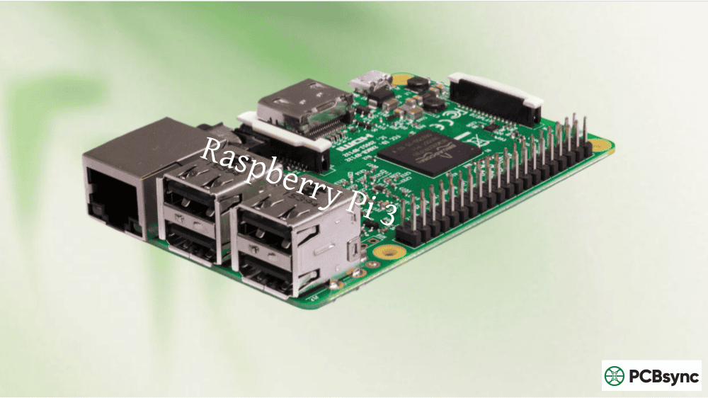
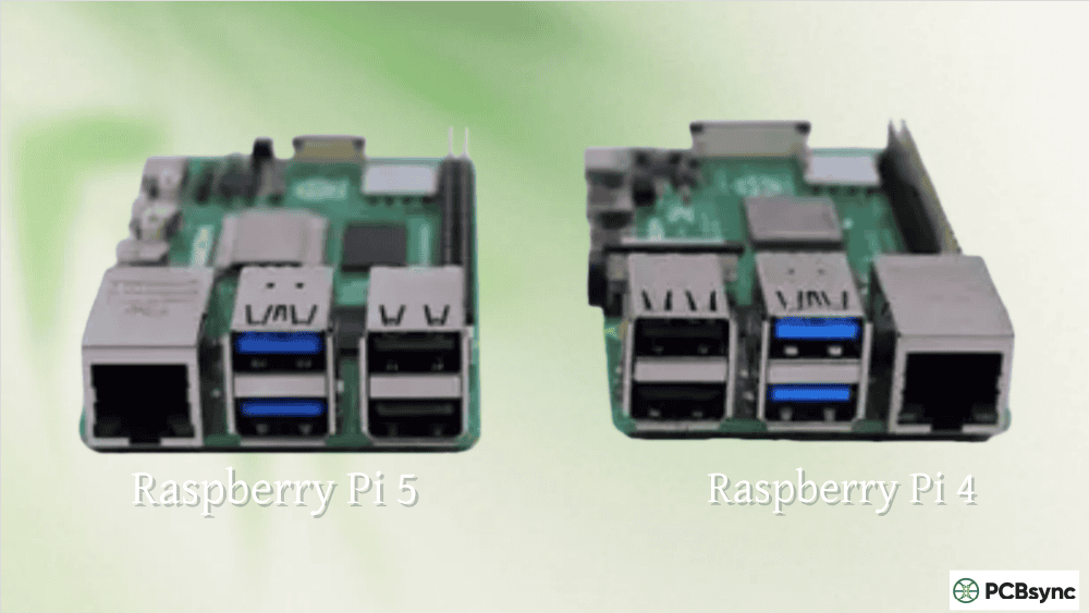
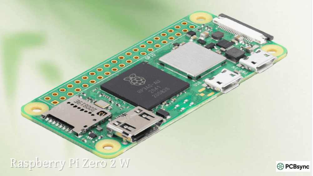
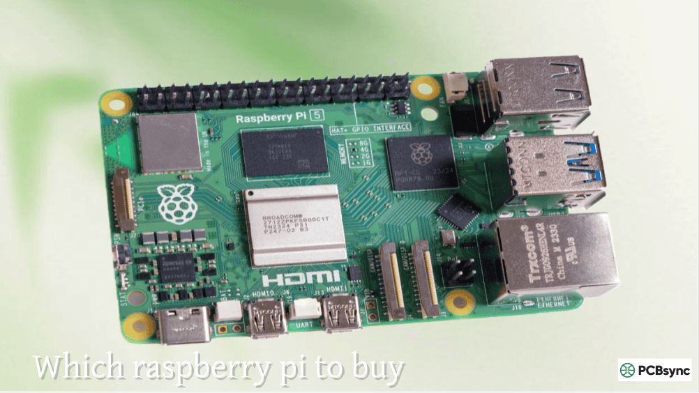
The 40-pin header layout has remained consistent across Raspberry Pi B+, 2, 3, 4, 5, and Zero models. Pin 1 sits in the top-left corner when you orient the board with the GPIO header on the right and HDMI ports on the left. Pin 1 is identifiable by its square solder pad on the underside of the PCB.
Full 40-Pin Header Pinout Table
Physical Pin
GPIO (BCM)
Function
Physical Pin
GPIO (BCM)
Function
1
–
3.3V Power
2
–
5V Power
3
GPIO 2
I2C1 SDA
4
–
5V Power
5
GPIO 3
I2C1 SCL
6
–
Ground
7
GPIO 4
GPCLK0 / 1-Wire
8
GPIO 14
UART TX
9
–
Ground
10
GPIO 15
UART RX
11
GPIO 17
General I/O
12
GPIO 18
PCM CLK / PWM0
13
GPIO 27
General I/O
14
–
Ground
15
GPIO 22
General I/O
16
GPIO 23
General I/O
17
–
3.3V Power
18
GPIO 24
General I/O
19
GPIO 10
SPI0 MOSI
20
–
Ground
21
GPIO 9
SPI0 MISO
22
GPIO 25
General I/O
23
GPIO 11
SPI0 SCLK
24
GPIO 8
SPI0 CE0
25
–
Ground
26
GPIO 7
SPI0 CE1
27
GPIO 0
ID EEPROM SDA
28
GPIO 1
ID EEPROM SCL
29
GPIO 5
General I/O
30
–
Ground
31
GPIO 6
General I/O
32
GPIO 12
PWM0
33
GPIO 13
PWM1
34
–
Ground
35
GPIO 19
PCM FS / PWM1
36
GPIO 16
General I/O
37
GPIO 26
General I/O
38
GPIO 20
PCM DIN
39
–
Ground
40
GPIO 21
PCM DOUT
This table shows the physical pin numbers alongside their BCM (Broadcom) GPIO numbers and primary functions. Keep this reference handy when wiring your projects.
Understanding GPIO Pin Numbering Systems
One of the most confusing aspects of the raspberry pi pinout for newcomers is the dual numbering system. Two completely different schemes exist for referencing the same physical pins, and mixing them up causes endless debugging headaches.
BCM (Broadcom) Numbering
BCM numbering refers to the GPIO channel numbers assigned by the Broadcom SoC (System on Chip). When you see “GPIO 17” in documentation or code, that’s BCM numbering. This scheme is what most Python libraries like gpiozero and RPi.GPIO expect when you select BCM mode.
The BCM numbers appear somewhat random when looking at the physical header because they reflect the chip’s internal architecture rather than any logical pin arrangement. For example, physical pin 11 corresponds to GPIO 17, while physical pin 12 maps to GPIO 18.
Physical (Board) Numbering
Physical numbering counts pins sequentially based on their position on the header. Pin 1 sits top-left, pin 2 is top-right, and they continue alternating down to pin 40. This system is intuitive when physically wiring components but requires looking up the BCM equivalent for programming.
Which Numbering System Should You Use?
For most projects, BCM numbering is the standard. Modern libraries default to it, and documentation typically references GPIO by BCM number. However, when working from a physical pinout diagram or following older tutorials, you might encounter board numbering.
The key is consistency. Pick one system and stick with it throughout your project. Mixing systems within the same codebase leads to confusion and potential hardware damage.
Power Pins on the Raspberry Pi Header
Not all raspberry pi pins handle data. Several provide power for external circuits, and misusing them can destroy your Pi or connected components.
3.3V Power Pins
Physical pins 1 and 17 supply regulated 3.3V power. This voltage matches the GPIO logic level, making these pins ideal for powering low-current sensors and small ICs. The combined current draw from both 3.3V pins should stay under 50mA for safety.
5V Power Pins
Physical pins 2 and 4 provide 5V directly from the Pi’s power input. These pins bypass the onboard voltage regulator, so they deliver whatever your power supply provides (typically 5V within tolerance). Use these for powering components that require 5V, but remember that the GPIO logic remains 3.3V.
Critical Warning: Never connect 5V directly to any GPIO pin. The Broadcom SoC operates at 3.3V logic levels. Applying 5V to a GPIO input will permanently damage your Raspberry Pi. If you’re interfacing with 5V devices, use a level shifter or voltage divider.
Ground Pins
Eight ground pins are distributed throughout the header at physical positions 6, 9, 14, 20, 25, 30, 34, and 39. Always connect external circuits to these ground pins to establish a common reference. Failing to share ground between circuits causes erratic behavior, incorrect readings, and potential damage.
Power Pin Summary Table
Pin Type
Physical Pins
Voltage
Notes
3.3V Power
1, 17
3.3V regulated
Max ~50mA combined
5V Power
2, 4
5V from supply
Directly from USB power
Ground
6, 9, 14, 20, 25, 30, 34, 39
0V
Essential for all circuits
Communication Protocol Pins Explained
Beyond simple digital I/O, the raspberry pi pinout includes dedicated pins for standard communication protocols. These interfaces dramatically expand what you can connect to your Pi.
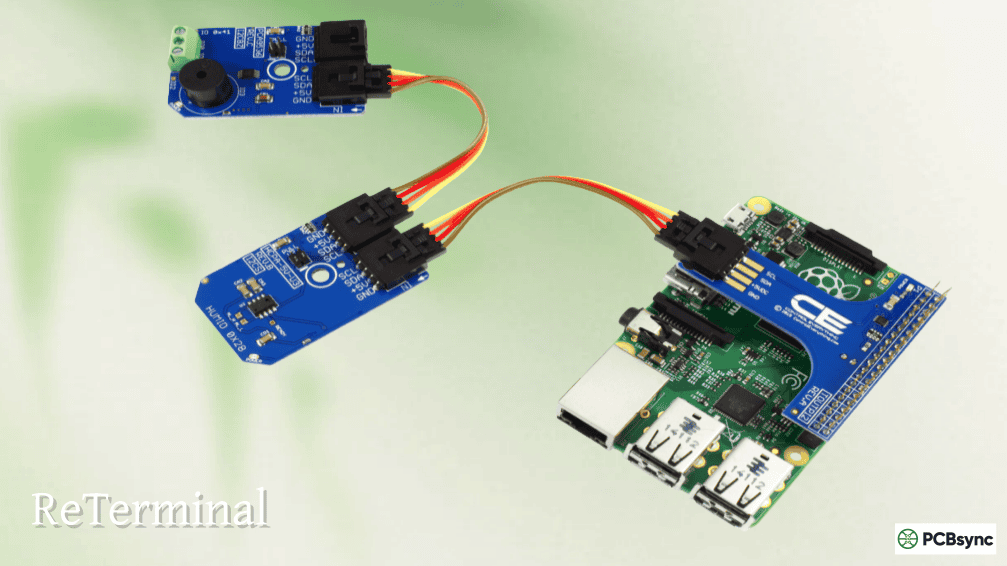
I2C (Inter-Integrated Circuit) Pins
I2C provides a two-wire interface for connecting multiple peripherals to the same bus. Sensors, displays, ADCs, and numerous other devices support I2C communication.
Pin Function
Physical Pin
GPIO (BCM)
SDA (Data)
3
GPIO 2
SCL (Clock)
5
GPIO 3
The Raspberry Pi includes fixed 1.8kΩ pull-up resistors on these pins, so external pull-ups are typically unnecessary. Each I2C device has a unique address (between 0x03 and 0x77), allowing up to 112 devices on a single bus theoretically.
To enable I2C on Raspberry Pi OS:
sudo raspi-config
# Navigate to: Interface Options > I2C > Enable
Detect connected I2C devices with:
sudo i2cdetect -y 1
Note: Pins 27 and 28 (GPIO 0 and GPIO 1) are reserved for HAT EEPROM identification. Don’t use these for general I2C communication unless you understand the implications.
SPI (Serial Peripheral Interface) Pins
SPI offers faster data transfer than I2C and works well for displays, SD cards, and high-speed sensors. The Raspberry Pi supports two SPI buses with multiple chip select lines.
Pin Function
Physical Pin
GPIO (BCM)
MOSI (Master Out)
19
GPIO 10
MISO (Master In)
21
GPIO 9
SCLK (Clock)
23
GPIO 11
CE0 (Chip Enable 0)
24
GPIO 8
CE1 (Chip Enable 1)
26
GPIO 7
SPI runs significantly faster than I2C, with the Pi supporting clock speeds up to 125MHz theoretically (though practical speeds depend on the peripheral). The tradeoff is that each SPI device requires its own chip enable line, limiting simultaneous connections.
Enable SPI through raspi-config under Interface Options, similar to I2C.
UART (Serial Communication) Pins
UART provides simple serial communication, commonly used for debugging, GPS modules, and communication between microcontrollers.
Pin Function
Physical Pin
GPIO (BCM)
TX (Transmit)
8
GPIO 14
RX (Receive)
10
GPIO 15
By default, Raspberry Pi OS uses these pins for the serial console. To use UART for other purposes, disable the console in raspi-config under Interface Options > Serial Port.
When connecting UART devices, remember to cross TX and RX lines. Your Pi’s TX connects to the peripheral’s RX, and vice versa. Also, ensure both devices share a common ground.
Communication Protocol Comparison
Protocol
Speed
Wires
Devices
Best For
I2C
Up to 400kHz (standard)
2
Multiple (127 max)
Sensors, small displays
SPI
Up to 125MHz
4+
Limited by CE pins
Displays, SD cards, fast sensors
UART
Up to 115200 baud typical
2
Point-to-point
Debug, GPS, microcontroller comm
PWM (Pulse Width Modulation) Pins
PWM signals control LED brightness, servo motor positions, and motor speeds. The Raspberry Pi provides both hardware and software PWM options.
Hardware PWM Pins
True hardware PWM runs independently of CPU load and provides stable, precise signals. Four GPIO pins support hardware PWM:
Physical Pin
GPIO (BCM)
PWM Channel
12
GPIO 18
PWM0
32
GPIO 12
PWM0
33
GPIO 13
PWM1
35
GPIO 19
PWM1
Note that GPIO 12 and 18 share PWM channel 0, while GPIO 13 and 19 share channel 1. You can only generate two independent hardware PWM signals simultaneously.
Software PWM
Any GPIO pin can produce software-generated PWM, but these signals depend on CPU timing and may jitter under load. For LED dimming or non-critical applications, software PWM works fine. For servo control or precision applications, hardware PWM is essential.
Working with raspberry pi pins requires careful attention to electrical specifications. I’ve seen plenty of dead Pis on lab benches, and most failures trace back to simple mistakes.
Voltage Limits
All GPIO pins operate at 3.3V logic levels. Input voltages above 3.3V damage the SoC permanently. When interfacing with 5V systems like Arduino Uno, use bidirectional level shifters or resistive voltage dividers.
Current Limits
Each GPIO pin can source or sink approximately 16mA safely. The total current across all GPIO pins should not exceed 50mA. For driving LEDs, always use appropriate current-limiting resistors (220Ω to 1kΩ typically).
ESD (Electrostatic Discharge) Protection
The BCM SoC has minimal ESD protection. Work on an anti-static mat and ground yourself before handling the Pi. In production designs, consider adding external ESD protection diodes on GPIO lines.
Hot Swapping Warning
Never connect or disconnect components while the Pi is powered. Hot-swapping causes voltage spikes that can damage both the Pi and your peripherals. Power down completely before making any wiring changes.
Useful Resources for Raspberry Pi GPIO Development
Resource
URL
Description
Pinout.xyz
pinout.xyz
Interactive pinout reference
Raspberry Pi Documentation
raspberrypi.com/documentation
Official hardware docs
gpiozero Documentation
gpiozero.readthedocs.io
Python GPIO library
SparkFun Pi Tutorials
learn.sparkfun.com
Hardware tutorials
Pi My Life Up GPIO Guide
pimylifeup.com/raspberry-pi-gpio
Beginner tutorials
BCM2835 Datasheet
raspberrypi.com/documentation
SoC technical reference
Random Nerd Tutorials
randomnerdtutorials.com
Project guides
Getting Started with GPIO Programming
For those ready to start using GPIO pins, here’s a minimal Python example using the gpiozero library:
from gpiozero import LED, Button
from time import sleep
# LED on GPIO 17 (physical pin 11)
led = LED(17)
# Button on GPIO 27 (physical pin 13)
button = Button(27)
# Turn LED on when button pressed
button.when_pressed = led.on
button.when_released = led.off
# Keep program running
while True:
sleep(1)
This example demonstrates both input (button) and output (LED) operations using BCM numbering. The gpiozero library handles pin configuration automatically, making it ideal for beginners.
Frequently Asked Questions About Raspberry Pi GPIO
What is the difference between BCM and BOARD pin numbering?
BCM numbering uses the Broadcom SoC’s internal GPIO channel numbers (like GPIO 17), while BOARD numbering counts physical pin positions on the header (1-40). Most modern Python libraries default to BCM. When programming, you specify which system you’re using at the start of your code. Physical pin 11 equals GPIO 17 in BCM terms.
Can I use 5V sensors with Raspberry Pi GPIO pins?
Not directly. All raspberry pi pins operate at 3.3V logic levels. Connecting 5V signals to GPIO inputs permanently damages the Broadcom SoC. Use a bidirectional logic level converter (like the TXB0108) or a resistive voltage divider to safely interface 5V devices with your Pi’s GPIO.
How many GPIO pins are available for general use?
The 40-pin header contains 26 GPIO pins technically, but practical availability depends on your needs. Subtracting I2C, SPI, and UART pins if you’re using those protocols leaves approximately 17-21 pins for general digital I/O. Pins 27 and 28 are reserved for HAT identification and shouldn’t be used for typical projects.
What is the maximum current I can draw from a GPIO pin?
Individual GPIO pins can safely source or sink up to 16mA. The combined current across all GPIO pins should stay below 50mA. For higher current loads, use transistors, MOSFETs, or driver ICs to switch the current rather than drawing it directly from GPIO. The 3.3V power pins can supply approximately 50mA total as well.
Do I need pull-up or pull-down resistors for GPIO inputs?
The Raspberry Pi includes internal pull-up and pull-down resistors that can be enabled through software. For most applications with switches and buttons, these internal resistors work fine. The I2C pins (GPIO 2 and 3) have fixed external 1.8kΩ pull-ups that cannot be disabled. For noise-sensitive applications or long wire runs, external resistors may provide better reliability.
Conclusion: Mastering the Raspberry Pi Pinout
The raspberry pi pinout represents the gateway between software and physical hardware. Understanding which pins handle power, communication protocols, and general I/O transforms a simple computer into a powerful embedded development platform.
Remember the critical points: always respect the 3.3V logic level limit, use appropriate current-limiting resistors, and never hot-swap connections. The 40-pin header design has remained consistent across modern Pi models specifically to ensure compatibility, so learning this layout once serves you for years of projects.
Start with simple LED circuits to build confidence with the GPIO pins, then progress to I2C sensors and SPI displays as your understanding grows. The Raspberry Pi’s GPIO interface balances accessibility for beginners with enough capability for sophisticated embedded systems work.
Keep this reference guide bookmarked. When you’re elbow-deep in wires at 2 AM trying to remember which pin is SPI MOSI, having a reliable raspberry pi pins reference makes all the difference between finishing your project and troubleshooting until sunrise.
Inquire: Call 0086-755-23203480, or reach out via the form below/your sales contact to discuss our design, manufacturing, and assembly capabilities.
Quote: Email your PCB files to Sales@pcbsync.com (Preferred for large files) or submit online. We will contact you promptly. Please ensure your email is correct.
Notes: For PCB fabrication, we require PCB design file in Gerber RS-274X format (most preferred), *.PCB/DDB (Protel, inform your program version) format or *.BRD (Eagle) format. For PCB assembly, we require PCB design file in above mentioned format, drilling file and BOM. Click to download BOM template To avoid file missing, please include all files into one folder and compress it into .zip or .rar format.


