Inquire: Call 0086-755-23203480, or reach out via the form below/your sales contact to discuss our design, manufacturing, and assembly capabilities.
Quote: Email your PCB files to Sales@pcbsync.com (Preferred for large files) or submit online. We will contact you promptly. Please ensure your email is correct.
Notes: For PCB fabrication, we require PCB design file in Gerber RS-274X format (most preferred), *.PCB/DDB (Protel, inform your program version) format or *.BRD (Eagle) format. For PCB assembly, we require PCB design file in above mentioned format, drilling file and BOM. Click to download BOM template To avoid file missing, please include all files into one folder and compress it into .zip or .rar format.
Python GPIO Tutorial: Control LEDs, Buttons, and Sensors on Raspberry Pi
After spending fifteen years designing PCBs and embedded systems, I can confidently say that the Raspberry Pi GPIO pins offer the most accessible entry point into hardware programming I’ve ever encountered. When clients ask me how to prototype sensor systems quickly, I always point them toward raspberry pi gpio python programming as the fastest path from concept to working hardware.
This python gpio tutorial covers everything from blinking your first LED to reading environmental sensors. Whether you’re building a home automation system or prototyping an industrial monitoring solution, the concepts here translate directly to real-world applications.
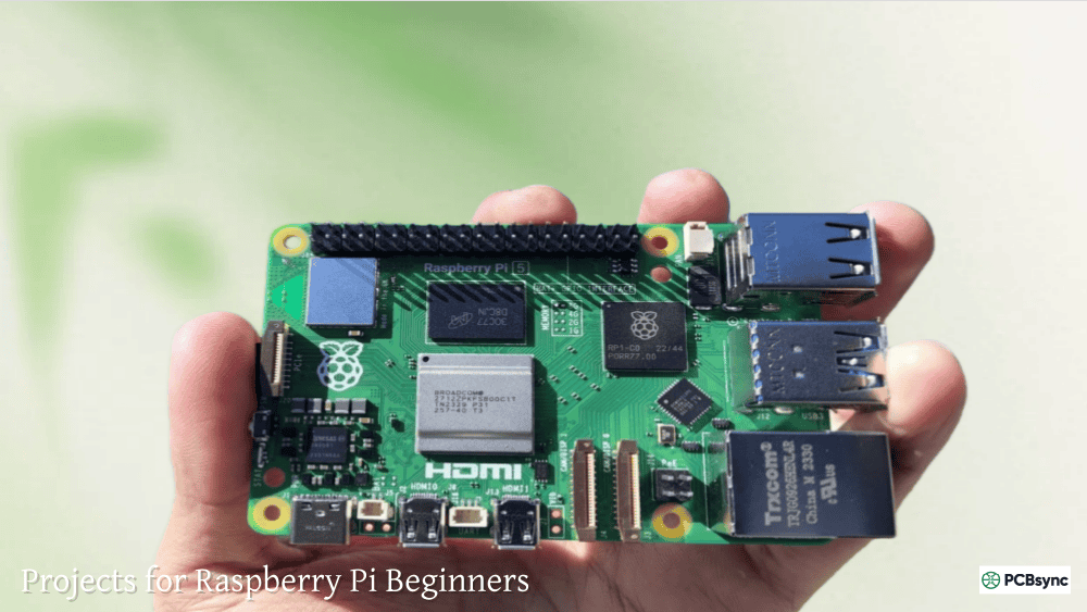
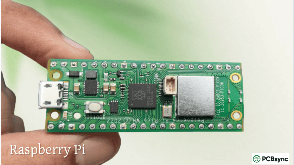
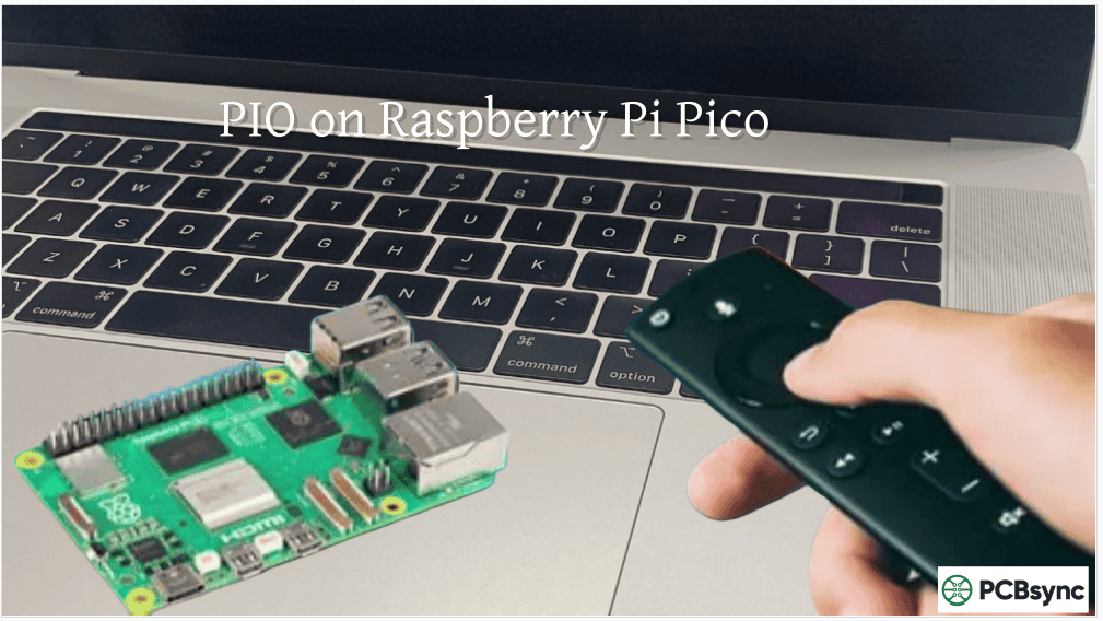
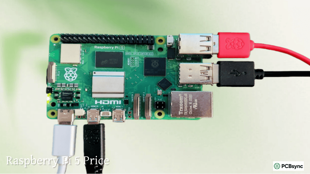
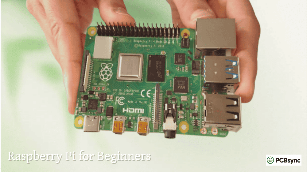
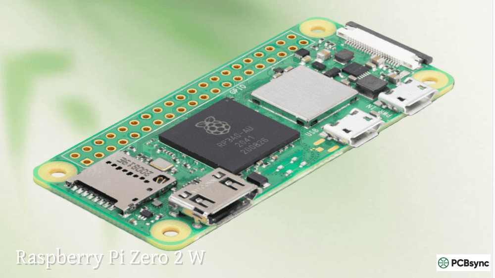
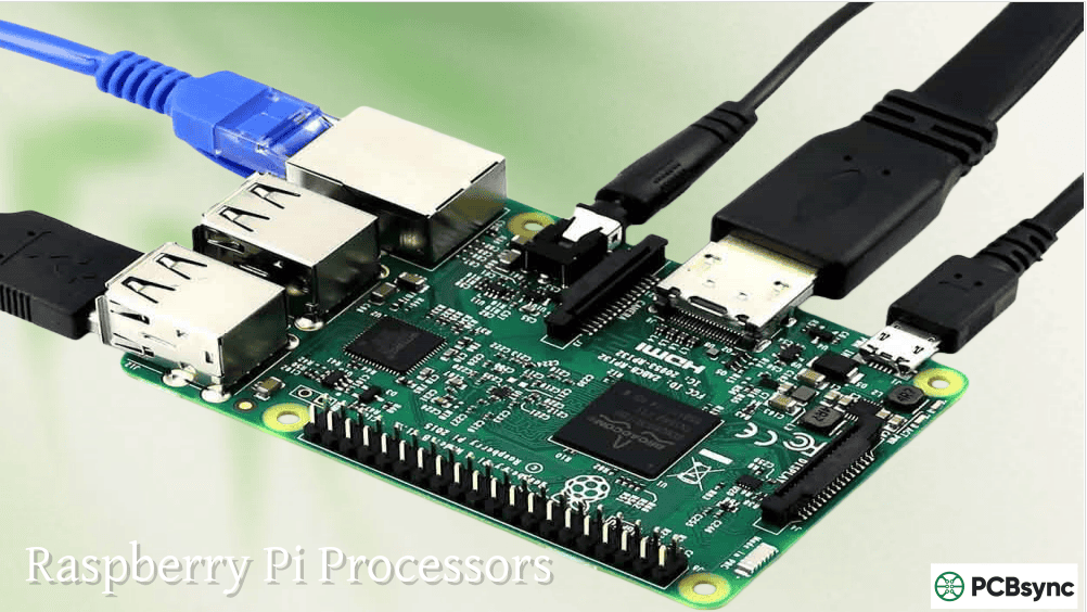
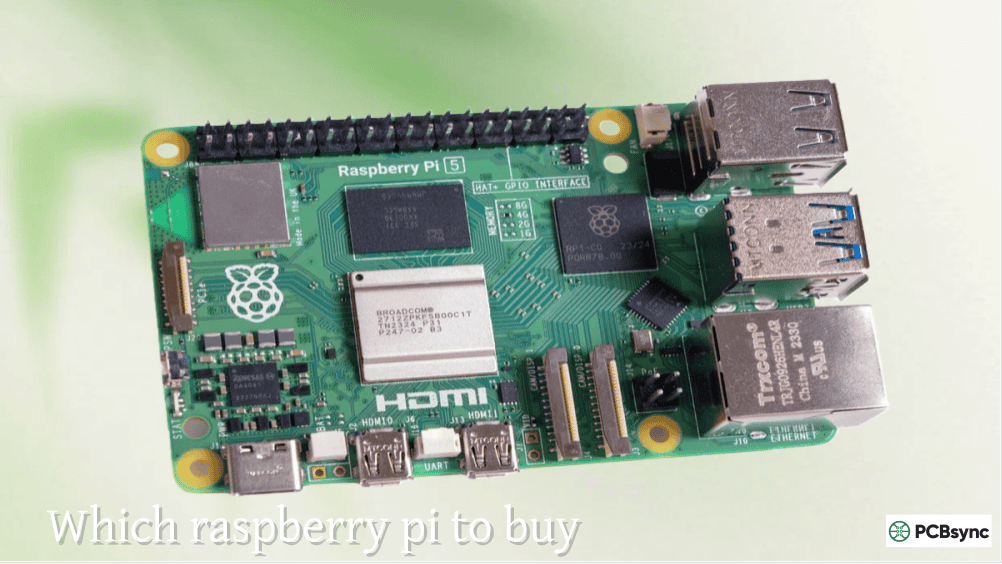
GPIO stands for General Purpose Input/Output. These are the 40 pins protruding from your Raspberry Pi board that interface directly with external hardware. Unlike USB or HDMI ports with fixed functions, GPIO pins are programmable. You decide whether each pin reads signals (input) or sends signals (output).
The Raspberry Pi’s GPIO operates at 3.3V logic levels. This is critical to remember because connecting 5V signals directly to GPIO pins will damage your board. I’ve seen this mistake destroy more than a few Pi boards in my workshop. Always verify voltage levels before connecting external circuits.
GPIO Pin Numbering Systems
One source of endless confusion for beginners is the dual numbering system. You can reference pins using either BCM (Broadcom) or BOARD numbering:
Numbering Mode
Description
Example
BCM
References GPIO channel numbers
GPIO17, GPIO27
BOARD
References physical pin positions
Pin 11, Pin 13
WiringPi
Alternative system (less common)
WPI0, WPI1
BCM numbering uses the Broadcom chip’s internal designation. When you see “GPIO17” on a pinout diagram, that’s BCM numbering. BOARD numbering simply counts pins from 1 to 40 starting at the corner near the microSD slot.
The gpiozero library uses BCM numbering exclusively, while RPi.GPIO lets you choose. I recommend sticking with BCM for consistency across different libraries and documentation.
GPIO Pin Types and Functions
Not all GPIO pins are created equal. Understanding the different pin types prevents frustration and hardware damage:
Pin Type
Description
Safe Current
Standard GPIO
Programmable input/output
16mA per pin
3.3V Power
Constant 3.3V output
~50mA total
5V Power
Constant 5V output
Limited by power supply
Ground (GND)
Reference ground
N/A
PWM Capable
Hardware PWM on GPIO12, 13, 18, 19
16mA per pin
I2C/SPI/UART
Serial communication protocols
16mA per pin
The maximum current any single GPIO pin can source or sink is approximately 16mA, with a combined maximum of roughly 50mA across all pins. Exceeding these limits damages the Pi’s processor. Always use current-limiting resistors and transistors for higher-current loads.
Setting Up Your Python GPIO Environment
Before writing any code, ensure your Raspberry Pi has the necessary libraries installed. Modern Raspberry Pi OS includes both major GPIO libraries pre-installed, but older installations may require manual setup.
Installing Required Libraries
Open a terminal and run these commands to verify and install the GPIO libraries:
The RPi.GPIO library provides low-level hardware access, while gpiozero offers a simpler, more intuitive interface. Both have their place depending on your project requirements.
For sensor projects requiring additional libraries, create a virtual environment to manage dependencies:
python3 -m venv gpio_project
source gpio_project/bin/activate
pip install adafruit-circuitpython-dht lgpio
Virtual environments prevent library conflicts and make projects more portable between different Pi installations.
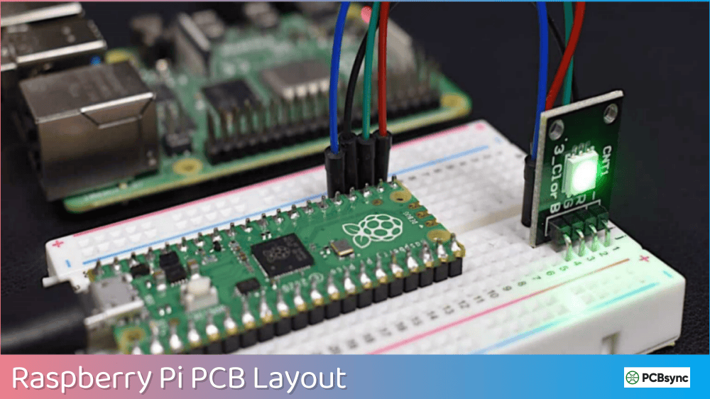
Controlling LEDs with Python GPIO
Every raspberry pi gpio python journey starts with blinking an LED. This simple project teaches fundamental concepts that apply to all GPIO programming.
Hardware Setup for LED Control
Gather these components:
Standard LED (any color)
330Ω resistor
Breadboard
Two male-to-female jumper wires
Connect the LED’s longer leg (anode) through the resistor to GPIO17 (BCM). Connect the shorter leg (cathode) to any ground pin. The resistor limits current flow, protecting both the LED and GPIO pin from damage.
Without that resistor, the LED would draw excessive current and either burn out immediately or damage your GPIO pin. I calculate resistor values using Ohm’s law: R = (Vsupply – Vled) / Iled. For a typical red LED with 2V forward voltage and 10mA target current: R = (3.3V – 2V) / 0.01A = 130Ω. A 330Ω resistor provides extra safety margin.
Basic LED Blink Script Using gpiozero
The gpiozero library makes LED control remarkably simple:
from gpiozero import LED
from time import sleep
led = LED(17)
while True:
led.on()
sleep(1)
led.off()
sleep(1)
Save this as blink.py and run it with python3 blink.py. The LED toggles on and off every second until you press Ctrl+C.
LED Control Using RPi.GPIO
For more granular control, RPi.GPIO exposes lower-level functionality:
import RPi.GPIO as GPIO
import time
GPIO.setmode(GPIO.BCM)
GPIO.setwarnings(False)
GPIO.setup(17, GPIO.OUT)
try:
while True:
GPIO.output(17, GPIO.HIGH)
print(“LED ON”)
time.sleep(1)
GPIO.output(17, GPIO.LOW)
print(“LED OFF”)
time.sleep(1)
except KeyboardInterrupt:
GPIO.cleanup()
The GPIO.cleanup() call resets pin states when your program exits, preventing unexpected behavior in subsequent scripts.
PWM for LED Brightness Control
Pulse Width Modulation allows variable LED brightness by rapidly switching the pin on and off:
from gpiozero import PWMLED
from time import sleep
led = PWMLED(17)
while True:
for brightness in range(0, 101, 5):
led.value = brightness / 100
sleep(0.1)
for brightness in range(100, -1, -5):
led.value = brightness / 100
sleep(0.1)
This creates a smooth fading effect. The human eye perceives the rapid on/off switching as variable brightness rather than flicker.
Reading Button Inputs with Python
Buttons and switches represent the simplest digital input devices. Understanding button reading unlocks interaction with countless sensors that output digital signals.
Wiring a Push Button
Connect one side of the button to GPIO4 and the other side to 3.3V. You’ll also need a pull-down resistor (10kΩ) from GPIO4 to ground. This resistor ensures the pin reads LOW when the button isn’t pressed, preventing floating inputs that cause erratic behavior.
Alternatively, enable the Pi’s internal pull-up or pull-down resistors through software, eliminating the external resistor requirement.
Reading Button State
The gpiozero library handles button reading elegantly:
from gpiozero import Button, LED
from signal import pause
button = Button(4)
led = LED(17)
button.when_pressed = led.on
button.when_released = led.off
pause()
This event-driven approach is cleaner than polling loops. The pause() function keeps the script running while waiting for button events.
The bouncetime parameter prevents multiple triggers from mechanical switch bounce, a common issue where button contacts vibrate briefly during presses.
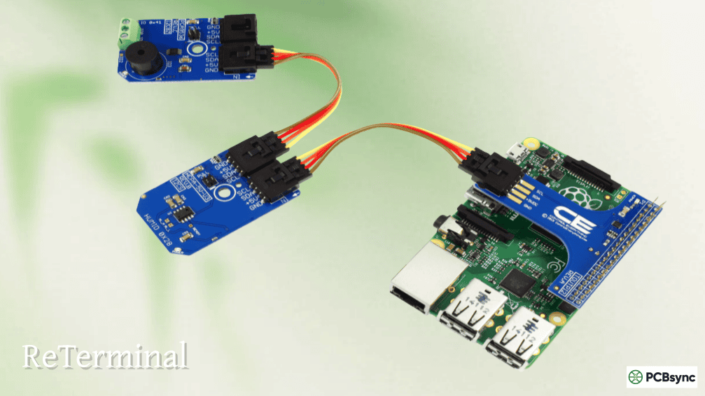
Interfacing Temperature and Humidity Sensors
The DHT11 and DHT22 sensors provide affordable temperature and humidity measurements, making them popular choices for environmental monitoring projects.
DHT11 vs DHT22 Specifications
Feature
DHT11
DHT22
Temperature Range
0-50°C
-40 to 80°C
Temperature Accuracy
±2°C
±0.5°C
Humidity Range
20-90%
0-100%
Humidity Accuracy
±5%
±2-5%
Sampling Rate
1Hz
0.5Hz
Price
Lower
Higher
The DHT22 offers better accuracy and wider range, but costs roughly twice as much. For indoor environmental monitoring, the DHT11 usually suffices.
Wiring DHT Sensors
DHT sensors typically have three or four pins. For three-pin modules (with built-in pull-up resistor):
VCC to 3.3V (or 5V for some modules)
GND to Ground
DATA to GPIO4
Four-pin versions require a 10kΩ pull-up resistor between VCC and DATA.
DHT sensors are notoriously finicky. The try/except block handles occasional read failures gracefully. Never sample faster than the sensor’s maximum rate or readings become unreliable.
Working with Motion Sensors (PIR)
Passive Infrared (PIR) motion sensors detect changes in infrared radiation, triggering when warm bodies (humans, animals) move within their detection range.
PIR Sensor Wiring
PIR modules have three pins:
VCC to 5V (most PIR sensors require 5V)
GND to Ground
OUT to GPIO17
The output pin produces a 3.3V signal when motion is detected, making it directly compatible with GPIO inputs despite the 5V power requirement.
Motion Detection Script
from gpiozero import MotionSensor, LED
from signal import pause
pir = MotionSensor(17)
led = LED(27)
pir.when_motion = led.on
pir.when_no_motion = led.off
pause()
This lights an LED whenever motion is detected. PIR sensors have sensitivity and delay adjustments via onboard potentiometers. Tune these for your specific application.
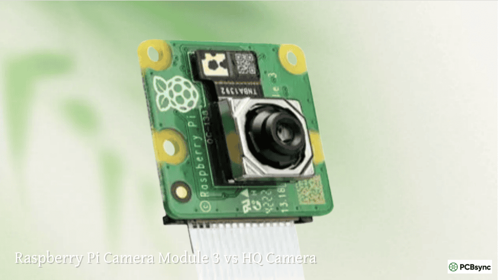
Motion-Activated Camera Example
Combining motion detection with the Pi camera creates a simple security system:
Servo motors rotate to specific angles based on PWM signal duty cycles. They’re essential for robotics, pan-tilt mechanisms, and automated physical controls.
Servo Wiring
Most hobby servos have three wires:
Red (VCC) to 5V (external power recommended)
Brown/Black (GND) to Ground
Orange/Yellow (Signal) to GPIO18
Important: Power servos from an external 5V supply rather than the Pi’s 5V pin. Servos draw significant current during movement, potentially causing brownouts that crash your Pi.
Servo Control with gpiozero
from gpiozero import Servo
from time import sleep
servo = Servo(18)
while True:
servo.min()
sleep(1)
servo.mid()
sleep(1)
servo.max()
sleep(1)
The min(), mid(), and max() methods correspond to approximately 0°, 90°, and 180° positions.
Precise Angle Control with RPi.GPIO
import RPi.GPIO as GPIO
import time
GPIO.setmode(GPIO.BCM)
GPIO.setup(18, GPIO.OUT)
pwm = GPIO.PWM(18, 50) # 50Hz frequency
pwm.start(0)
def set_angle(angle):
duty = (angle / 18) + 2.5
pwm.ChangeDutyCycle(duty)
time.sleep(0.3)
try:
while True:
for angle in range(0, 181, 30):
set_angle(angle)
print(f”Angle: {angle}°”)
for angle in range(180, -1, -30):
set_angle(angle)
print(f”Angle: {angle}°”)
except KeyboardInterrupt:
pwm.stop()
GPIO.cleanup()
The duty cycle calculation maps angles to the 2.5%-12.5% range that most servos expect. Adjust these values based on your specific servo’s datasheet.
This script logs temperature, humidity, and motion presence whenever the button is pressed, demonstrating how multiple GPIO components work together.
Useful Resources and Downloads
Resource
URL
Description
gpiozero Documentation
gpiozero.readthedocs.io
Official library documentation
RPi.GPIO Wiki
sourceforge.net/p/raspberry-gpio-python/wiki
Low-level library reference
Pinout.xyz
pinout.xyz
Interactive GPIO pinout diagram
Adafruit CircuitPython
learn.adafruit.com
Sensor libraries and tutorials
Raspberry Pi Documentation
raspberrypi.com/documentation
Official hardware guides
GPIO Zero Recipes
gpiozero.readthedocs.io/en/stable/recipes.html
Ready-to-use code examples
Best Practices for GPIO Programming
After years of building GPIO-based systems, these practices prevent most common problems:
Always use current-limiting resistors with LEDs. The 330Ω value works for most standard LEDs at 3.3V.
Never connect 5V signals directly to GPIO pins. Use level shifters or voltage dividers when interfacing with 5V devices.
Implement proper exception handling. The try/except/finally pattern ensures GPIO cleanup even when scripts crash.
Use external power for motors and servos. The Pi’s 5V rail cannot supply adequate current for most motors.
Enable internal pull-up or pull-down resistors for switches. This eliminates floating inputs without external components.
Add debouncing for mechanical switches. Either use software delays (bouncetime parameter) or hardware RC circuits.
Frequently Asked Questions
What is the difference between gpiozero and RPi.GPIO?
The gpiozero library provides a higher-level, object-oriented interface that simplifies common tasks. It handles pin cleanup automatically and uses intuitive methods like led.on() and button.when_pressed. RPi.GPIO offers lower-level access with more control over timing and pin behavior, but requires more boilerplate code. For beginners, gpiozero is easier. For complex timing-critical applications, RPi.GPIO provides finer control.
Can I damage my Raspberry Pi by connecting components incorrectly?
Yes, incorrect wiring can permanently damage GPIO pins or the entire board. The most common mistakes include connecting 5V signals to 3.3V GPIO pins, shorting power to ground, and exceeding maximum current limits. Always double-check connections before powering on, use appropriate resistors, and start with low-risk components like LEDs before progressing to more complex circuits.
How many GPIO pins can I use simultaneously?
The Raspberry Pi has 26 usable GPIO pins on the 40-pin header. All can function simultaneously, but current limits apply. The combined current draw from all GPIO pins should not exceed approximately 50mA. For projects requiring many outputs, use transistors or driver ICs to handle current-intensive components.
Why does my DHT sensor give frequent errors?
DHT sensors communicate using precise timing that can be disrupted by the Pi’s multitasking operating system. Errors are normal and expected. Always wrap DHT reads in try/except blocks and implement retry logic. Ensure you’re not sampling faster than the sensor’s maximum rate (1 second for DHT11, 2 seconds for DHT22). Using the Adafruit CircuitPython library generally provides more reliable results than older libraries.
How do I run my GPIO script automatically at boot?
Several methods work for auto-starting GPIO scripts. The simplest is adding your script to /etc/rc.local before the “exit 0” line. For better control, create a systemd service file. Alternatively, use crontab with the @reboot directive. Ensure your script includes proper error handling since it will run without user intervention.
Troubleshooting Common GPIO Problems
Even experienced engineers encounter GPIO issues. Here are solutions to problems I see repeatedly:
“RuntimeError: No access to /dev/mem”
This error occurs when running GPIO scripts without proper permissions. Either run your script with sudo (sudo python3 script.py) or add your user to the gpio group:
sudo usermod -a -G gpio $USER
Log out and back in for group changes to take effect.
GPIO Pin Stays HIGH After Script Ends
Without proper cleanup, pins retain their last state. Always include GPIO.cleanup() in a finally block or use gpiozero which handles this automatically. For scripts that crash unexpectedly, run a cleanup script:
import RPi.GPIO as GPIO
GPIO.setmode(GPIO.BCM)
GPIO.cleanup()
Servo Motor Jitters or Vibrates
Software PWM timing can cause servo jitter. Solutions include using hardware PWM pins (GPIO12, 13, 18, 19), the pigpio library for DMA-based timing, or dedicated servo controller boards like the PCA9685 for multiple servos.
Button Triggers Multiple Times Per Press
Mechanical switch bounce causes rapid on/off transitions. Add the bouncetime parameter to event detection (typically 200-300ms) or implement software debouncing with a minimum time between accepted presses.
Advanced GPIO Techniques
Using Multiple Libraries Together
Some projects benefit from combining gpiozero’s simplicity with RPi.GPIO’s flexibility:
from gpiozero import LED
import RPi.GPIO as GPIO
# Use gpiozero for simple LED control
status_led = LED(27)
# Use RPi.GPIO for precise PWM timing
GPIO.setmode(GPIO.BCM)
GPIO.setup(18, GPIO.OUT)
pwm = GPIO.PWM(18, 1000) # 1kHz for audio tones
Both libraries coexist peacefully when using consistent BCM numbering.
Interrupt-Driven Programming
For responsive systems, interrupts outperform polling:
This pattern allows your main loop to perform other tasks while remaining responsive to hardware events.
Taking Your GPIO Skills Further
This python gpio tutorial covered the fundamentals, but the real learning happens through building projects. Start simple with LED patterns and button combinations, then gradually incorporate sensors and actuators.
The raspberry pi gpio python ecosystem continues expanding with new libraries and sensors. The skills you’ve developed here apply directly to weather stations, home automation systems, robotics, and industrial monitoring applications.
Consider exploring I2C and SPI protocols next. These communication buses allow connecting multiple sensors and displays to just a few GPIO pins, dramatically expanding your project possibilities.
Join the Raspberry Pi community forums and GitHub repositories. Thousands of makers share code, troubleshoot problems, and inspire new project ideas daily. The collective knowledge available accelerates learning far beyond solo experimentation.
Experiment, break things, and rebuild them better. That’s how every good hardware engineer learns.
Inquire: Call 0086-755-23203480, or reach out via the form below/your sales contact to discuss our design, manufacturing, and assembly capabilities.
Quote: Email your PCB files to Sales@pcbsync.com (Preferred for large files) or submit online. We will contact you promptly. Please ensure your email is correct.
Notes: For PCB fabrication, we require PCB design file in Gerber RS-274X format (most preferred), *.PCB/DDB (Protel, inform your program version) format or *.BRD (Eagle) format. For PCB assembly, we require PCB design file in above mentioned format, drilling file and BOM. Click to download BOM template To avoid file missing, please include all files into one folder and compress it into .zip or .rar format.


