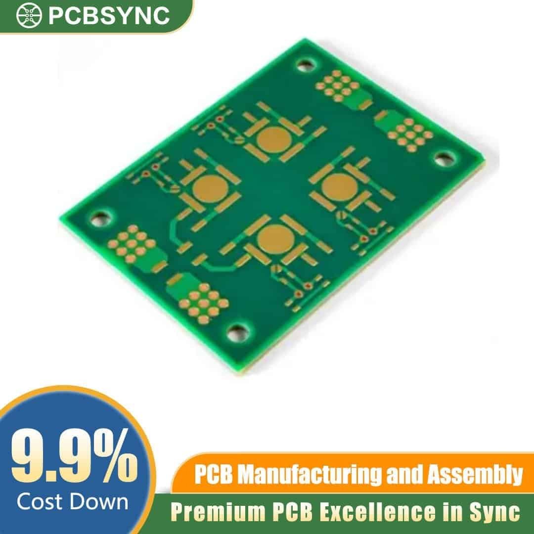
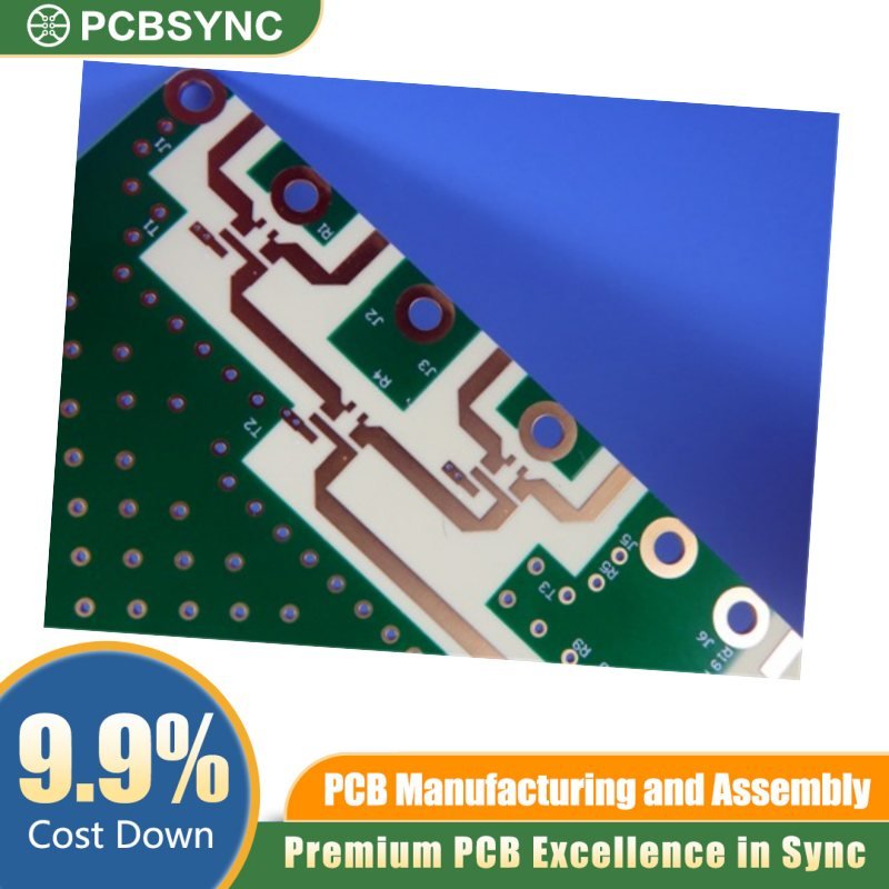
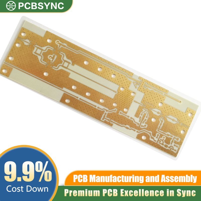
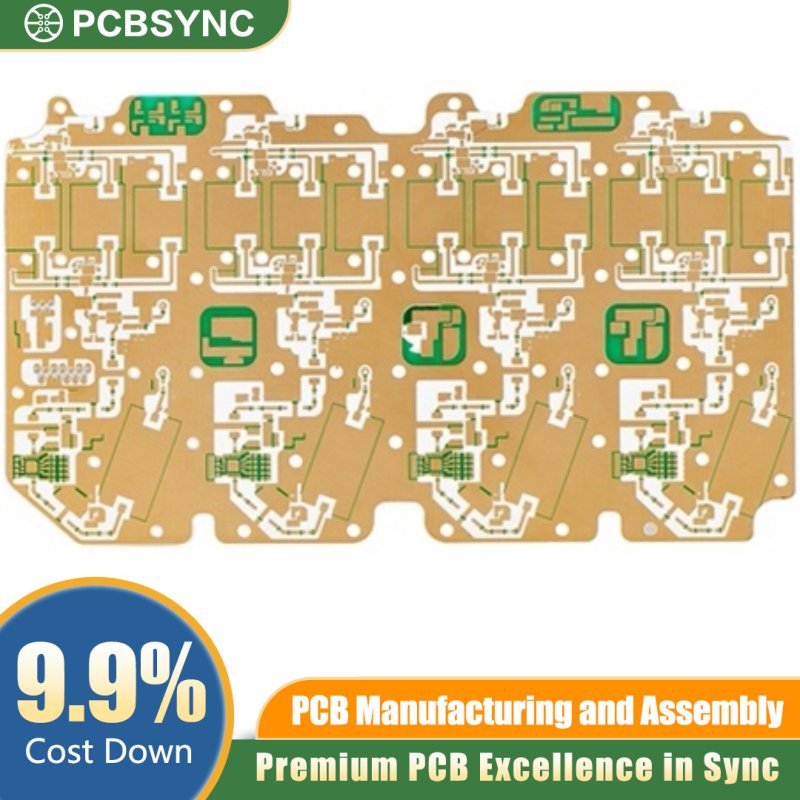
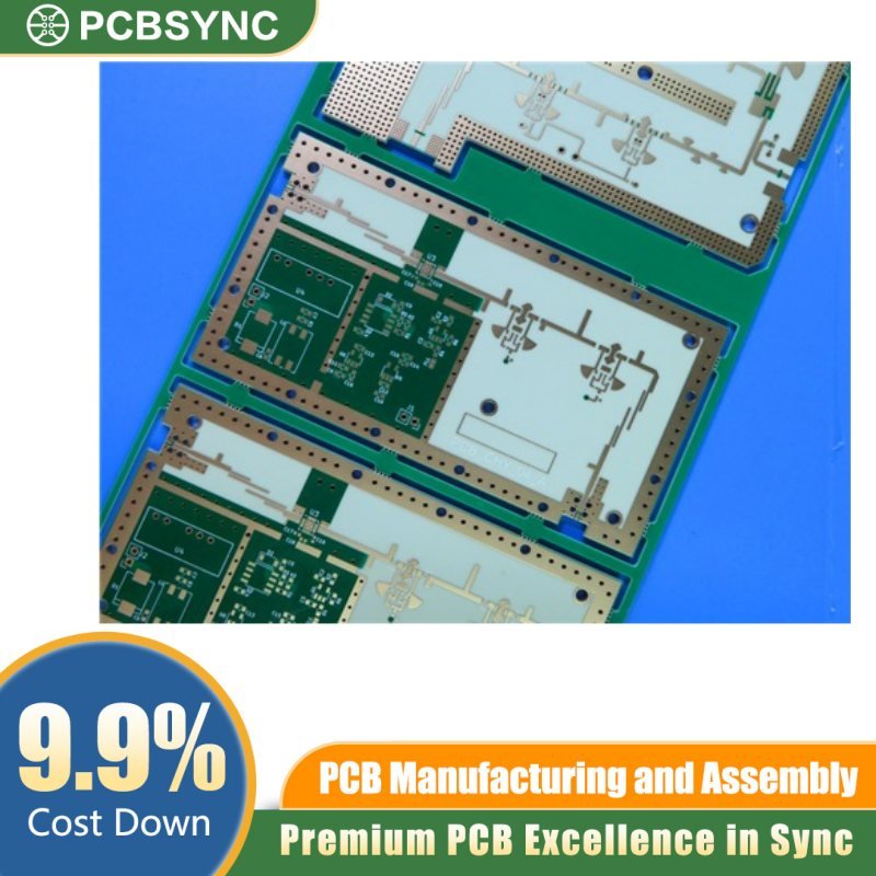
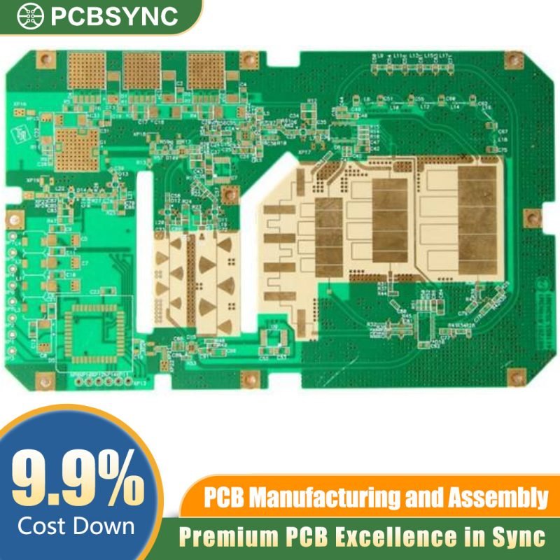
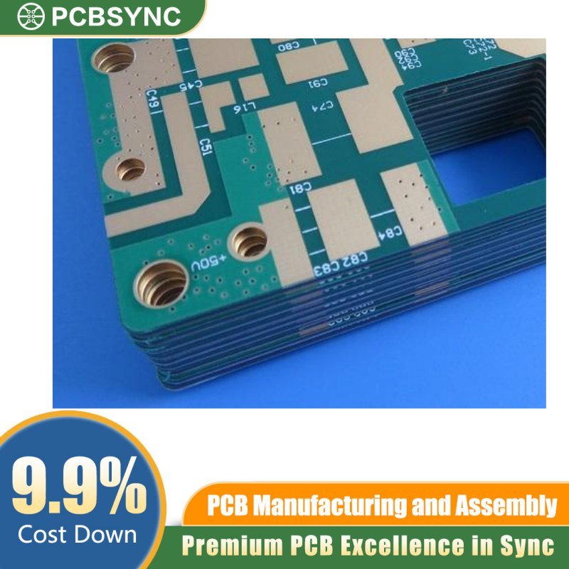
Precision-Engineered Multi-Layer RF Circuit Board for High-Frequency Applications
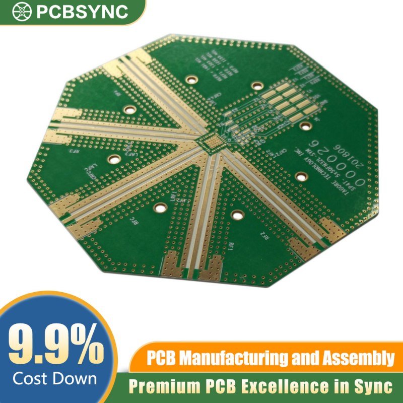
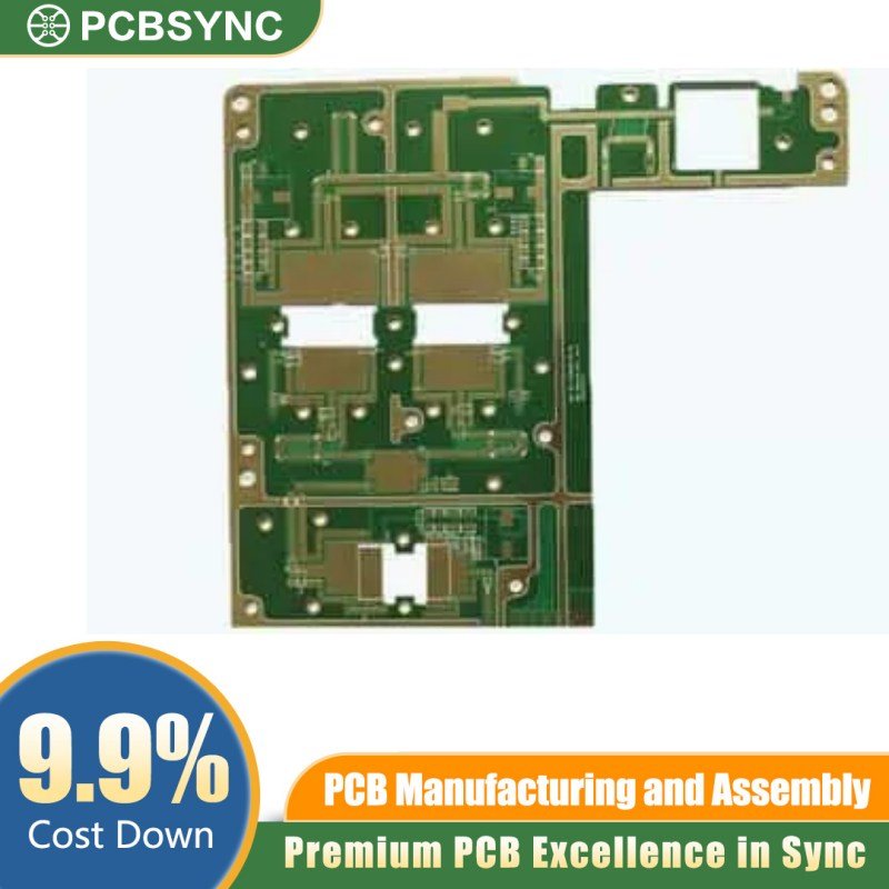
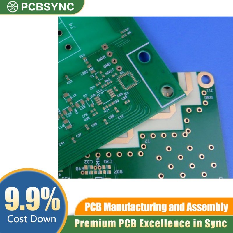
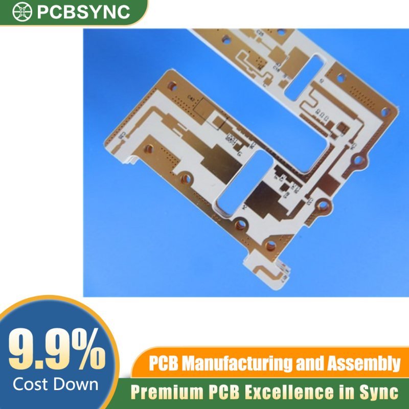
Achieve superior signal integrity and thermal reliability with PCBSync’s RO4500 14-layer complex RF system PCB — purpose-built for demanding high-frequency, mixed-signal, and radar applications where performance is non-negotiable.
Product Overview
This advanced 14-layer PCB is fabricated on Rogers RO4500 series laminate, a thermoset material specifically formulated for complex multilayer RF designs. With a finished board thickness of 2.0mm, 2oz copper weight, and a hard gold surface finish, this board delivers the electrical performance, mechanical durability, and connector reliability that mission-critical RF systems demand.
Rogers RO4500 offers a stable dielectric constant across a wide frequency range, low insertion loss, and excellent compatibility with standard FR-4 fabrication processes — making it the ideal substrate choice when your design requires RF-grade performance without exotic manufacturing constraints.
Key Specifications
- Material: Rogers RO4500 Series (Hydrocarbon/Ceramic Thermoset)
- Layer Count: 14 Layers
- Board Thickness: 2.0mm
- Copper Weight: 2oz (70µm) finished
- Surface Finish: Hard Gold (Electrolytic Nickel/Gold)
- Application Class: Complex RF / Microwave Systems
Why Choose This PCB?
Exceptional RF Performance Rogers RO4500 maintains a tightly controlled dielectric constant (Er) with minimal variation over frequency and temperature. This ensures consistent impedance matching, predictable transmission line behavior, and low-loss signal propagation across your entire operating bandwidth — critical for applications spanning L-band through Ka-band.
14-Layer Stackup Versatility A 14-layer construction supports complex routing architectures, including dedicated RF signal layers, stripline and microstrip configurations, embedded power/ground planes for shielding, and separate digital/analog routing zones. This stackup density is ideal for integrated transceiver modules, phased array feeds, and multi-function RF assemblies.
2oz Copper for Power and Thermal Management Heavy 2oz copper on all layers provides lower DC resistance, improved current-carrying capacity, and enhanced thermal dissipation — essential in power amplifier stages, high-duty-cycle radar transmitters, and densely packed RF front-end modules.
Hard Gold Finish for Maximum Durability The electrolytic hard gold surface finish delivers outstanding wear resistance for edge connectors, press-fit contacts, and high-insertion-cycle interfaces. Unlike ENIG or immersion finishes, hard gold withstands repeated mating cycles without degradation, ensuring long-term connection reliability in field-deployed systems.
Ideal Applications
- Radar and electronic warfare (EW) systems
- Satellite communication (SATCOM) modules
- 5G mmWave infrastructure and antenna systems
- Aerospace and defense RF assemblies
- Software-defined radio (SDR) platforms
- Point-to-point microwave backhaul
- Medical RF imaging equipment
Why PCBSync?
At PCBSync, we specialize in high-complexity, high-reliability PCB fabrication for RF and microwave applications. Every board undergoes rigorous impedance testing, cross-section analysis, and electrical verification to ensure your design performs exactly as simulated. From prototype to volume production, we deliver the quality, consistency, and technical support that RF engineers trust.
Ready to order or need a custom stackup? Contact our RF engineering team for a tailored quote.