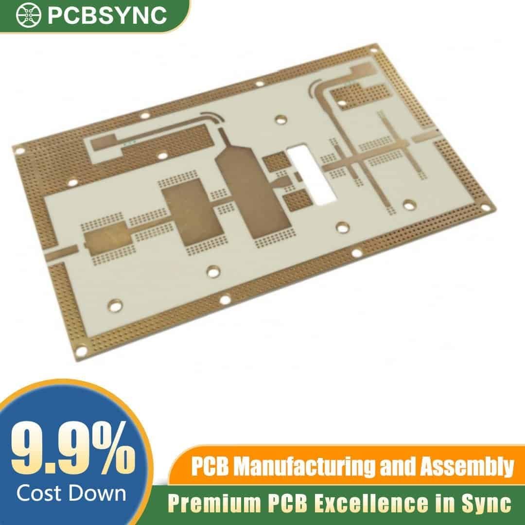
Engineered for demanding RF and microwave applications, the RO4003C 0.4mm 1/2oz ENIG 2-Layer Flexible Microwave PCB delivers exceptional electrical performance, dimensional stability, and signal integrity for next-generation wireless, aerospace, and high-frequency electronic designs. Manufactured by PCBSync to IPC Class 2/3 standards, this thin-profile, high-frequency circuit board is the ideal choice for engineers who need woven-glass reinforced hydrocarbon ceramic laminate performance without the cost of pure PTFE-based materials.
Premium Rogers RO4003C High-Frequency Laminate
The Rogers RO4003C substrate is widely recognized as an industry benchmark for low-loss RF circuitry. Its tightly controlled dielectric constant (Dk 3.38) and low dissipation factor (Df 0.0027 at 10 GHz) ensure minimal signal attenuation across a broad frequency range. Combined with a low Z-axis CTE and high thermal conductivity, RO4003C maintains stable electrical properties under varying temperatures and humidity—critical for mission-critical RF assemblies.
Key Technical Specifications
- Base Material: Rogers RO4003C (woven glass-reinforced hydrocarbon ceramic)
- Board Thickness: 0.4 mm (ultra-thin profile for flex-tolerant designs)
- Layer Count: 2-Layer (double-sided)
- Copper Weight: 1/2 oz (≈17 µm) on outer layers
- Surface Finish: ENIG (Electroless Nickel Immersion Gold) – flat, lead-free, RoHS compliant
- Dielectric Constant (Dk): 3.38 ± 0.05
- Loss Tangent (Df): 0.0027 @ 10 GHz
- Operating Frequency: Optimized for 1 GHz – 40 GHz applications
- UL Rating: 94V-0
- Compliance: RoHS, REACH
Why Choose This Microwave PCB
The 0.4 mm thin-core construction offers a degree of mechanical flexibility uncommon in standard rigid microwave laminates, making it well-suited for compact enclosures, conformal antenna arrays, and tight-bend installations where space and weight are constrained. The 1/2 oz copper weight provides a fine-line etching capability ideal for impedance-controlled microstrip, stripline, and grounded coplanar waveguide (GCPW) structures.
Our ENIG surface finish delivers a uniformly flat solderable pad, excellent for fine-pitch BGAs, QFNs, and high-frequency connectors. ENIG resists oxidation, supports multiple reflow cycles, and improves long-term reliability in harsh operating environments.
Typical Applications
- 5G base stations and small cell radios
- Phased-array and patch antenna systems
- Automotive radar (24 GHz / 77 GHz)
- Satellite communication modules
- Aerospace and defense RF systems
- LNB, LNA, and power amplifier circuits
- IoT and high-speed digital backplanes
Manufactured by PCBSync — Quality You Can Verify
At PCBSync, every RO4003C order is fabricated in our ISO 9001 and IATF 16949 certified facility, with full traceability from raw laminate to final electrical test. We provide impedance control documentation (TDR reports), microsection analysis on request, and 100% AOI plus flying-probe testing to guarantee yield. Standard lead times start at 5 working days, with expedited options available for prototype and pre-production builds.
Order your RO4003C 0.4mm ENIG 2-Layer Microwave PCB today and experience the precision, repeatability, and RF performance trusted by engineers worldwide. Upload your Gerber files for an instant online quote, or contact our application engineering team for design-for-manufacturability (DFM) feedback before production.