Precision-Engineered for the Final Frontier: High-Frequency Reliability in a Micro-Form Factor
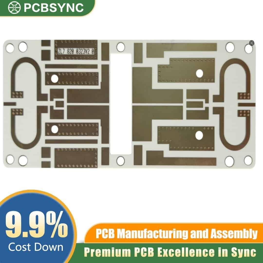
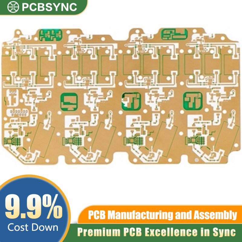
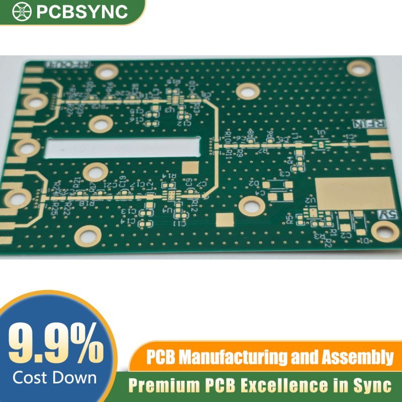
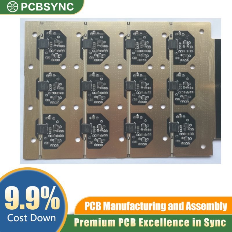
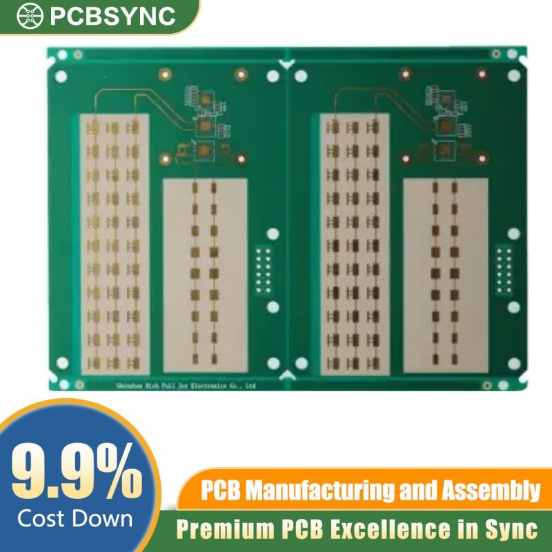
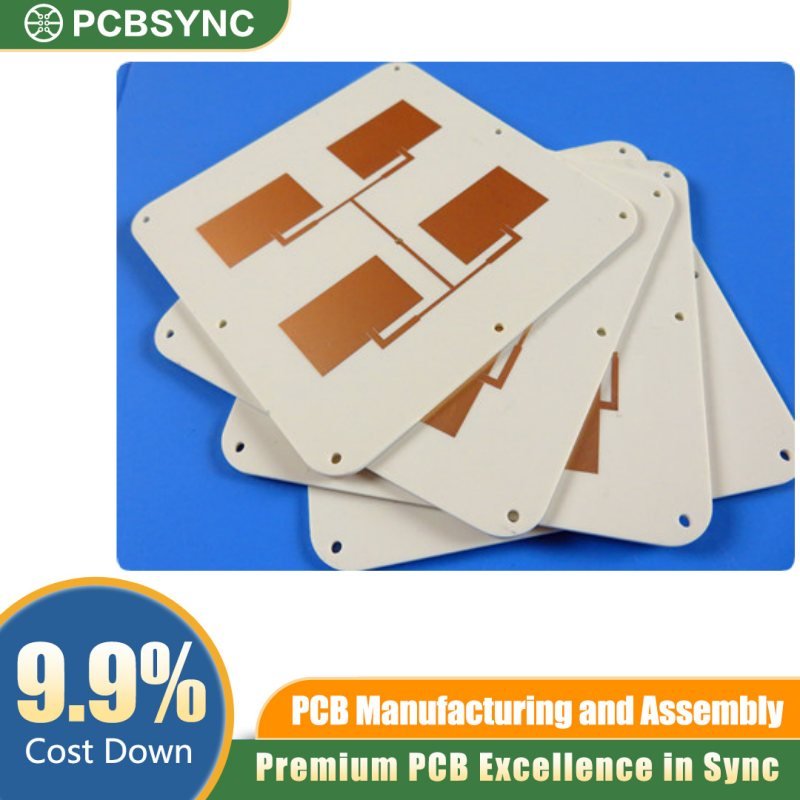
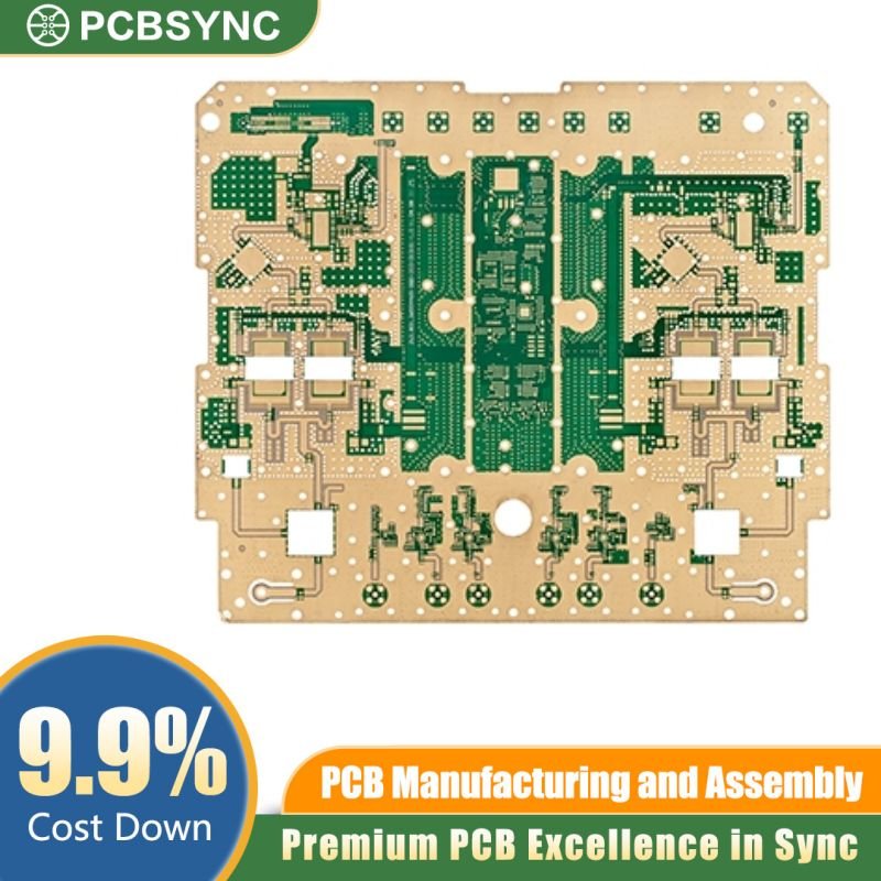
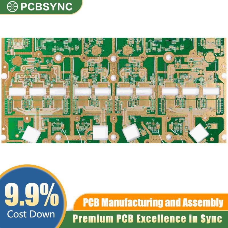
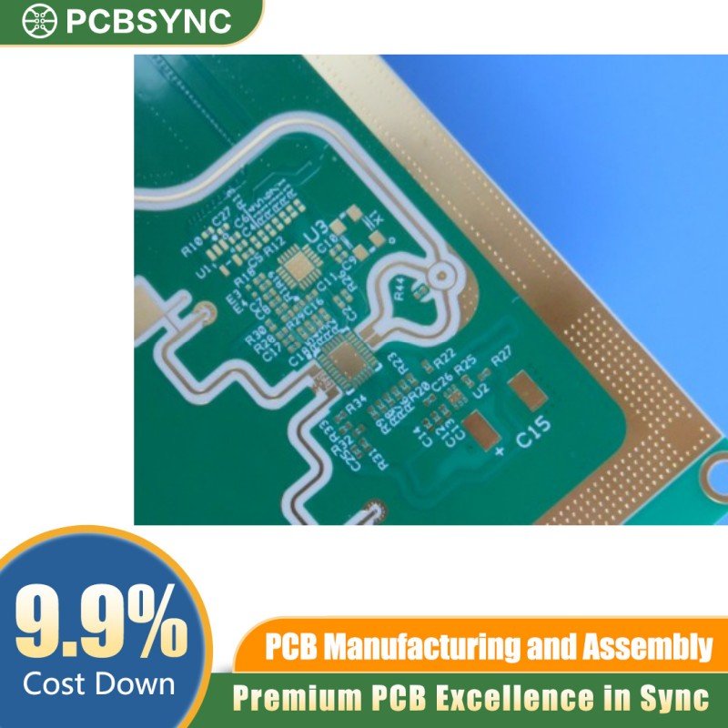
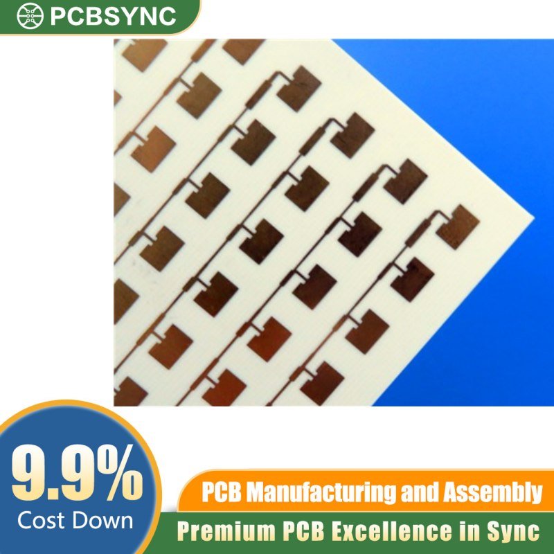
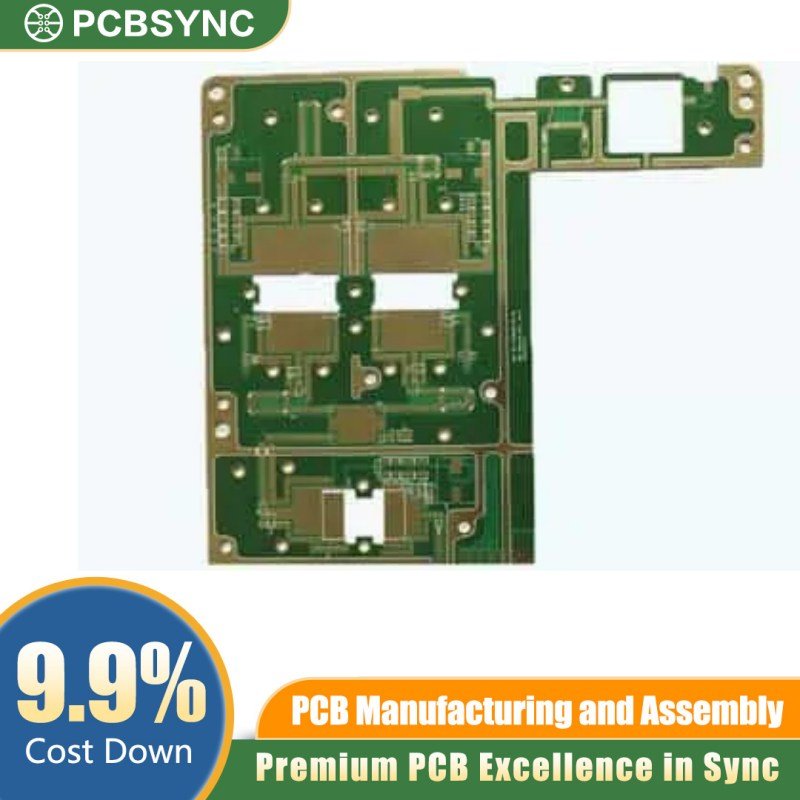
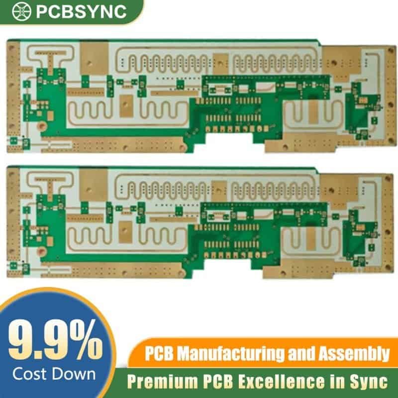
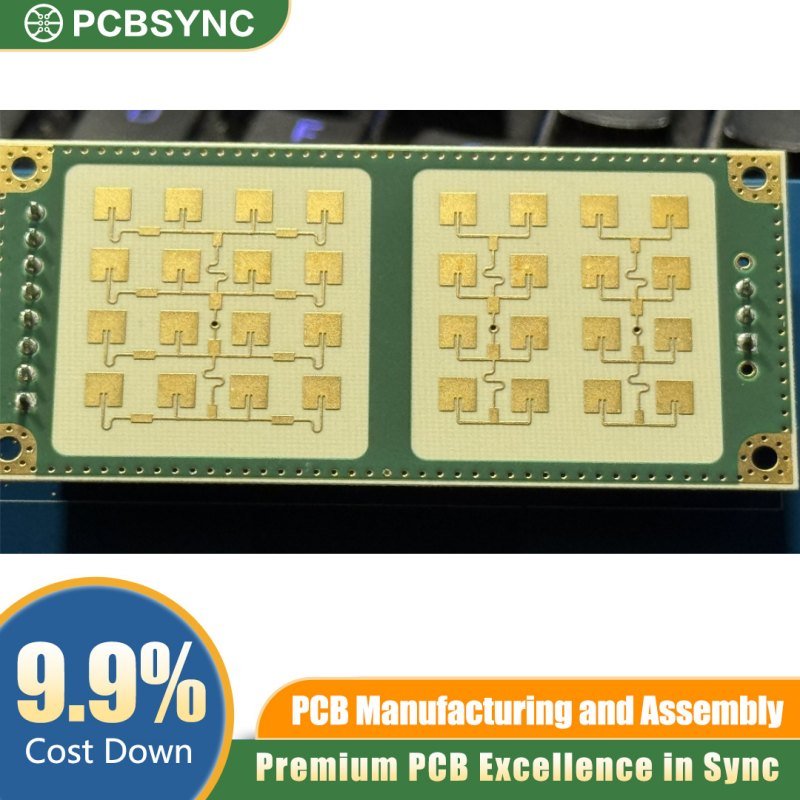
In the demanding landscape of aerospace and satellite communications, every millimeter and milligram counts. The RO3035 0.4mm Ultra-Compact PCB is designed to meet these rigorous standards, offering unparalleled thermal stability and signal integrity for high-frequency applications. Built on the industry-leading Rogers RO3035 high-frequency ceramic-filled PTFE laminate, this 2-layer board is the definitive choice for engineers developing CubeSats, phased array antennas, and advanced RF modules.
Core Technical Specifications
-
Substrate Material: Rogers RO3035 (Ceramic-filled PTFE)
-
Board Thickness: 0.4mm (Ultra-Thin Profile)
-
Copper Weight: 1oz (35µm) Finished Copper
-
Surface Finish: ENIG (Electroless Nickel Immersion Gold)
-
Layer Count: 2-Layer High-Precision Stackup
-
Application Focus: Satellite Communications, RF Microstrip Circuits, and Power Amplifiers
Why Choose RO3035 for Satellite Applications?
1. Exceptional Dielectric Consistency
The RO3035 material offers a low dielectric constant ($D_k$) of 3.50 and a dissipation factor ($D_f$) of 0.0015 at 10 GHz. This ensures minimal signal loss and consistent impedance control across wide frequency bands, which is critical for satellite transponders and telemetry systems where signal degradation is not an option.
2. Ultra-Thin 0.4mm Profile
The 0.4mm thickness is specifically optimized for ultra-compact enclosures. This reduced Z-axis profile allows for tighter integration in multi-stack satellite architectures without sacrificing mechanical rigidity. The thin substrate also facilitates shorter via lengths, reducing parasitic inductance and enhancing high-speed performance.
3. Superior Thermal Management & Stability
Space environments subject electronics to extreme temperature fluctuations. RO3035 features a low Coefficient of Thermal Expansion (CTE) in the X and Y axes ($17 ppm/°C$), closely matching the expansion rate of copper. This thermal stability prevents trace delamination and maintains solder joint integrity during intense thermal cycling.
4. ENIG Finish for Longevity
The Electroless Nickel Immersion Gold (ENIG) surface finish provides a flat, solderable surface ideal for fine-pitch SMT components and wire bonding. Beyond its planarity, ENIG offers excellent oxidation resistance, ensuring a long shelf life and reliable performance in the vacuum of space.
Optimization for Modern RF Design
This PCB is engineered to support frequencies reaching into the Ka-band and beyond. The 1oz copper weight provides the necessary current-carrying capacity for power distribution while maintaining the precision required for complex RF routing. Whether you are designing a low-noise amplifier (LNA) or a compact GPS receiver, the RO3035 substrate provides the low-loss environment necessary for peak efficiency.
PCBSync Quality Assurance
At PCBSync, we understand that satellite missions allow for zero failure. Our RO3035 boards undergo rigorous AOI (Automated Optical Inspection) and flying probe testing to ensure 100% netlist adherence. We source only genuine Rogers materials to guarantee that the electrical properties of your finished board match your simulations perfectly.
Order the RO3035 0.4mm ENIG 2-Layer PCB today to power your next mission-critical aerospace project with precision and reliability.