Inquire: Call 0086-755-23203480, or reach out via the form below/your sales contact to discuss our design, manufacturing, and assembly capabilities.
Quote: Email your PCB files to Sales@pcbsync.com (Preferred for large files) or submit online. We will contact you promptly. Please ensure your email is correct.
Notes: For PCB fabrication, we require PCB design file in Gerber RS-274X format (most preferred), *.PCB/DDB (Protel, inform your program version) format or *.BRD (Eagle) format. For PCB assembly, we require PCB design file in above mentioned format, drilling file and BOM. Click to download BOM template To avoid file missing, please include all files into one folder and compress it into .zip or .rar format.
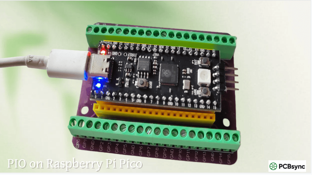
PIO on Raspberry Pi Pico: Unlock Advanced I/O Capabilities
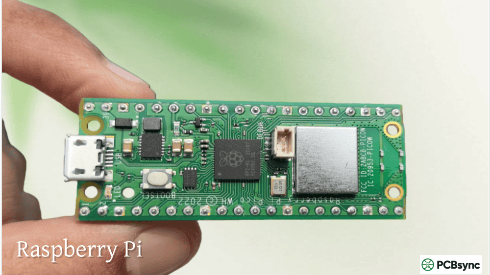
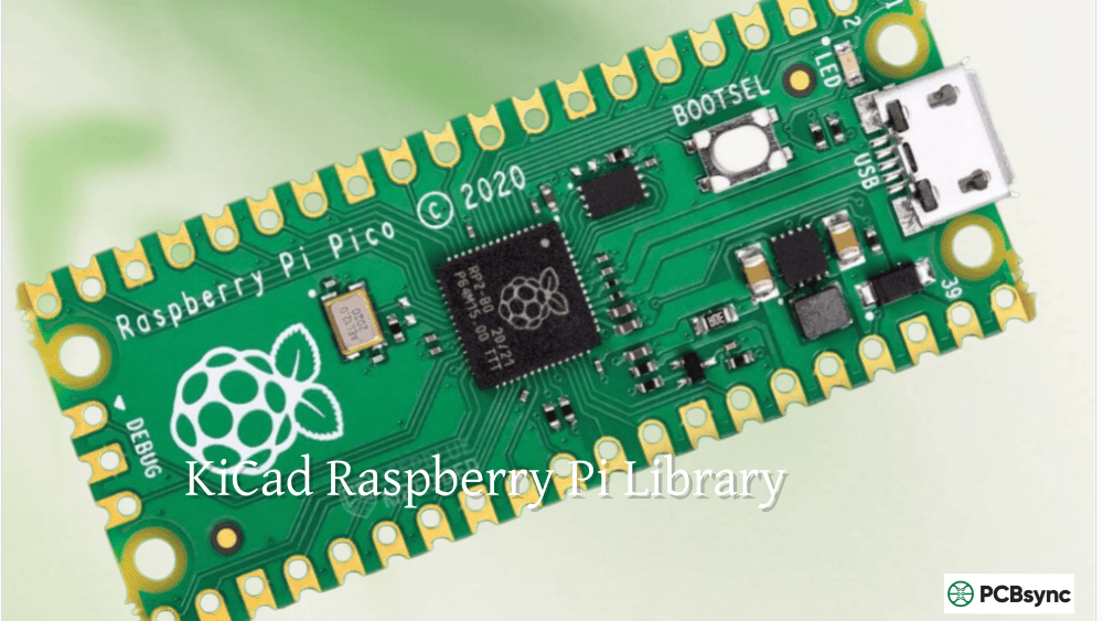
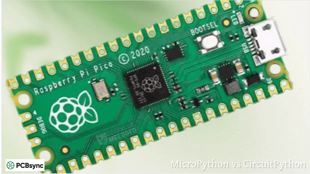
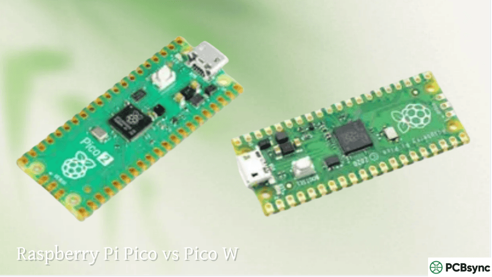
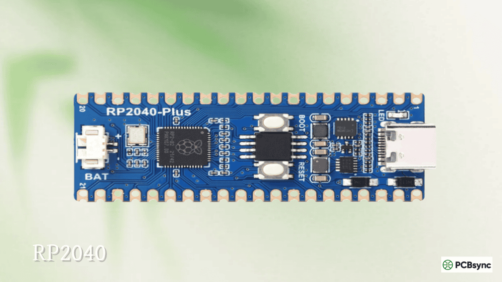
When the Raspberry Pi Foundation released the Pico in 2021, one feature immediately caught the attention of embedded systems engineers: Programmable I/O, or PIO. This wasn’t just another GPIO peripheral—it was essentially a set of programmable co-processors dedicated to handling I/O operations independently of the main CPU cores.
Having spent considerable time working with various microcontrollers, I can say that RP2040 PIO represents a genuine paradigm shift in how we approach custom protocol implementation. Instead of bit-banging with precious CPU cycles or hunting for specialized peripheral chips, PIO lets you create virtually any digital interface directly on the Raspberry Pi Pico.
PIO stands for Programmable Input/Output. At its core, PIO provides hardware-level I/O processing that operates completely independently from the main ARM Cortex-M0+ cores. Think of it as having dedicated mini-processors whose sole job is moving bits in and out of GPIO pins with cycle-accurate timing.
The RP2040 chip contains two PIO blocks. Each block houses four state machines, giving you eight total state machines to work with. These state machines execute tiny programs written in a specialized assembly language, processing GPIO operations at speeds up to the full system clock (133 MHz by default).
Why PIO Matters for Embedded Development
Traditional microcontrollers force you into one of two scenarios when implementing non-standard protocols:
Bit-banging: You write code that manually toggles GPIO pins with precise timing. This works but consumes CPU resources and becomes unreliable when interrupts occur or when timing requirements are strict.
External hardware: You add dedicated chips to handle specific protocols, increasing BOM cost, board complexity, and power consumption.
RP2040 PIO eliminates both problems. The state machines handle timing-critical I/O operations in hardware while your main program focuses on application logic. The result is deterministic timing that doesn’t care what else the CPU is doing.
RP2040 PIO Architecture Overview
Understanding PIO requires grasping its internal structure. Each PIO block is a self-contained subsystem with shared resources among its four state machines.
PIO Block Components
Component
Description
Quantity per Block
State Machines
Independent execution units
4
Instruction Memory
Shared program storage
32 instructions
TX FIFO
Outgoing data buffer
4 words per SM
RX FIFO
Incoming data buffer
4 words per SM
Scratch Registers (X, Y)
Temporary data storage
2 per SM
Shift Registers (ISR, OSR)
Data shifting for serial I/O
2 per SM
Each state machine operates independently but shares the 32-word instruction memory with other state machines in the same PIO block. This means multiple state machines can run the same program simultaneously (useful for multiple identical interfaces) or run completely different programs.
State Machine Registers
Every state machine has access to several registers that make serial communication possible:
Register
Function
X
32-bit scratch register for temporary data and loop counters
Y
32-bit scratch register for temporary data and loop counters
ISR
Input Shift Register – accumulates incoming bit data
OSR
Output Shift Register – holds outgoing bit data
PC
Program Counter – tracks current instruction
The shift registers are particularly important. When receiving data, bits shift into the ISR one at a time until you have a complete word to push to the RX FIFO. When transmitting, you pull data from the TX FIFO into the OSR and shift bits out to the pins.
The PIO Instruction Set
PIO programs use an extremely minimal instruction set—just nine instructions handle everything. This simplicity is intentional; it keeps the hardware small while still enabling complex protocols.
Complete PIO Instruction Reference
Instruction
Function
Typical Use
JMP
Conditional/unconditional jump
Loops, state changes
WAIT
Pause until condition met
Synchronization, edge detection
IN
Shift data from source to ISR
Reading pin states
OUT
Shift data from OSR to destination
Writing to pins
PUSH
Transfer ISR contents to RX FIFO
Sending data to CPU
PULL
Transfer TX FIFO contents to OSR
Receiving data from CPU
MOV
Copy data between registers
Data manipulation
IRQ
Set or clear interrupt flags
CPU notification
SET
Immediately set pins or registers
Pin control, initialization
Each instruction executes in exactly one clock cycle (plus optional delay cycles). This deterministic timing is what makes PIO suitable for protocols with strict timing requirements.
Side-Set and Delay Features
Two powerful features extend PIO’s capabilities without consuming extra instructions:
Side-set: Allows an instruction to simultaneously toggle additional pins. For example, you can shift data out while toggling a clock pin—both happen in the same cycle.
Delay: Each instruction can include a delay of 0-31 additional cycles. This stretches timing without wasting instruction memory on NOP operations.
Practical Applications for Raspberry Pi Pico PIO
The real power of PIO becomes apparent when you see what it can implement. Here are proven use cases from the embedded community.
WS2812 NeoPixel LED Control
NeoPixel LEDs require a precise single-wire protocol with timing tolerances around ±150ns. Traditional bit-banging struggles here because any interrupt disrupts timing and corrupts the data stream.
PIO handles NeoPixels effortlessly. A simple 4-instruction program generates the required waveforms while the CPU prepares the next frame of pixel data. You can drive hundreds of LEDs without any CPU involvement during transmission.
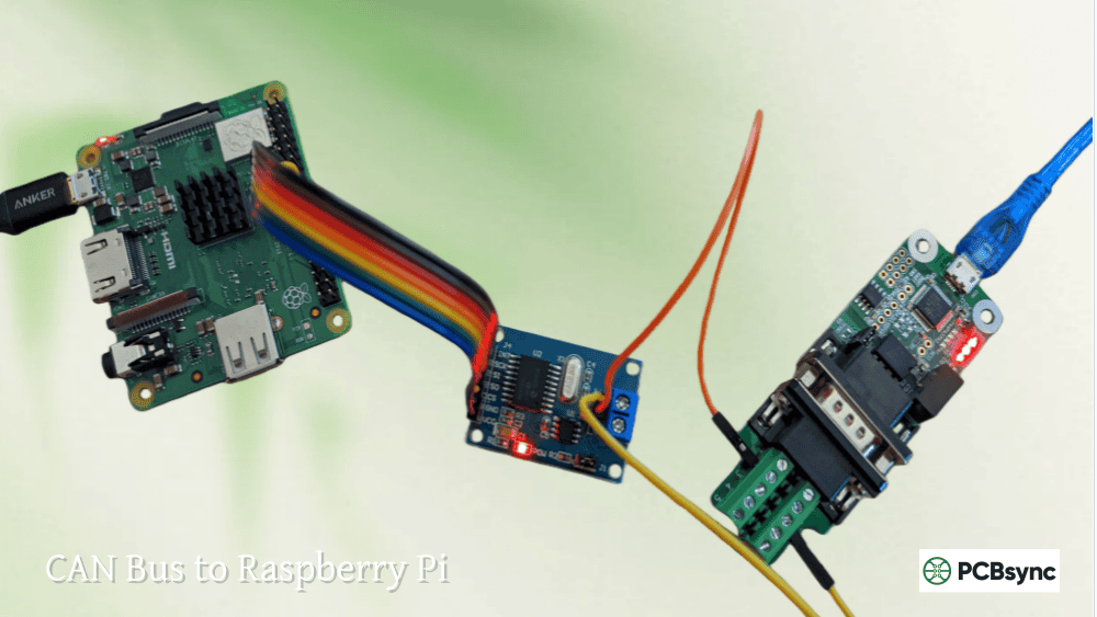
Implement automotive networking without external transceivers
Quadrature Encoder
Count encoder pulses without missing any during high speeds
Custom Serial
Interface with legacy or proprietary devices
The can2040 library, for instance, implements a complete CAN bus controller using PIO—no external CAN controller chip required. This demonstrates how PIO can replace dedicated peripheral hardware.
Parallel Data Interfaces
Need to read an 8-bit parallel bus? PIO can sample all eight pins simultaneously and pack the data into 32-bit words automatically. This is invaluable for interfacing with parallel flash, legacy displays, or high-speed ADCs.
Programming PIO with MicroPython
MicroPython provides an accessible entry point for PIO programming. The rp2 module includes decorators that let you write PIO assembly directly in your Python code.
Basic PIO Program Structure
A MicroPython PIO program consists of:
Assembly function decorated with @rp2.asm_pio()
StateMachine initialization that loads the program
Data exchange via put() and get() methods
The decorator configures initial pin states and shift directions. Inside the function, you write PIO assembly using Python function calls that mirror the actual instructions.
State Machine Configuration Options
Parameter
Purpose
freq
Clock frequency for the state machine (Hz)
set_base
First GPIO pin for SET instructions
out_base
First GPIO pin for OUT instructions
in_base
First GPIO pin for IN instructions
sideset_base
First GPIO pin for side-set operations
jmp_pin
GPIO pin used for conditional jumps
The frequency parameter is particularly important. Setting freq=5_000_000 (5 MHz) means each instruction cycle takes 200ns—perfect for protocols like WS2812 that need specific timing in the microsecond range.
For production applications or when you need maximum control, the Pico C/C++ SDK provides comprehensive PIO support.
PIO File Structure
C/C++ PIO programs live in .pio files containing two sections:
Program section: Pure PIO assembly with directives like .program, .wrap_target, and .wrap
C-SDK section: Helper functions that configure the state machine from your main program
The build system automatically processes .pio files and generates header files with the compiled program and helper functions.
Key SDK Functions
Function
Purpose
pio_add_program()
Load program into PIO instruction memory
pio_claim_sm_mask()
Reserve state machine(s) for your use
pio_sm_init()
Initialize state machine with configuration
pio_sm_set_enabled()
Start or stop state machine execution
pio_sm_put()
Write data to TX FIFO
pio_sm_get()
Read data from RX FIFO
DMA Integration for Zero-CPU Transfers
PIO becomes even more powerful when combined with the RP2040’s DMA controller. You can set up DMA channels to automatically feed data to PIO or collect data from it—completely without CPU involvement.
This combination enables scenarios like:
Streaming audio to an I2S DAC while the CPU processes the next buffer
Capturing high-speed parallel data into memory
Driving complex LED displays with pre-computed frame data
The DMA controller watches the FIFO levels and transfers data as needed, creating a fully autonomous I/O pipeline.
Common PIO Development Challenges
Working with PIO isn’t without its learning curve. Here are issues I’ve encountered and their solutions.
Timing Calculation
Getting timing right requires understanding the relationship between system clock, state machine frequency, instruction cycles, and delays. The formula:
Instruction time = (1 / state_machine_freq) × (1 + delay_cycles)
For a 125 MHz system clock with no clock divider, each instruction takes 8ns. Adding [31] delay extends this to 256ns (32 total cycles × 8ns).
Debugging PIO Programs
Unlike regular code, you can’t step through PIO programs with a debugger. Instead:
Use a logic analyzer to verify signal timing
Add IRQ instructions to signal program progress
Use the PIO emulator (rp2040pio-docs) for offline testing
Start simple and add complexity incrementally
Instruction Memory Limits
With only 32 instructions per PIO block shared among four state machines, space is precious. Techniques for managing this:
Use .wrap for free jumps at program end
Leverage side-set to combine operations
Share programs between state machines when possible
Use the second PIO block for additional programs
Useful Resources and Downloads
Here are essential resources for mastering Raspberry Pi Pico PIO:
Official Documentation:
RP2040 Datasheet (Chapter 3 covers PIO in detail): https://datasheets.raspberrypi.com/rp2040/rp2040-datasheet.pdf
How fast can PIO operate compared to software bit-banging?
PIO state machines can toggle GPIO pins at up to half the system clock frequency—62.5 MHz at the default 125 MHz clock, or even faster if you overclock. Software bit-banging on the Cortex-M0+ cores typically maxes out around 10-15 MHz due to instruction overhead. More importantly, PIO maintains consistent timing regardless of interrupts or other CPU activity.
Can I use PIO with Arduino IDE on the Raspberry Pi Pico?
Yes. The arduino-pico core by Earle Philhower includes full PIO support. You can write PIO programs in .pio files just like with the C SDK, and the Arduino build system handles compilation. The core also includes pre-built PIO libraries for common protocols like WS2812 LEDs.
What happens if two state machines need to access the same GPIO pin?
Each GPIO pin can only be controlled by one state machine at a time for output operations. However, multiple state machines can read the same input pin simultaneously. For complex protocols requiring coordinated multi-pin control, you typically use one state machine or carefully partition pin assignments between state machines.
Is PIO similar to an FPGA?
PIO shares some conceptual similarities with FPGAs—both allow custom hardware-like behavior through programming. However, PIO is much simpler. FPGAs implement arbitrary digital logic; PIO state machines execute sequential programs focused specifically on I/O operations. Think of PIO as a middle ground between software bit-banging and custom silicon.
How do I debug PIO programs when things go wrong?
Start with a logic analyzer to verify actual signal timing against your expectations. The PIO emulator (rp2040pio-docs) lets you step through programs and inspect internal state on your development machine. You can also add IRQ instructions to your PIO program that trigger callbacks in your main code, helping you understand program flow. When all else fails, simplify your PIO program to the minimum that reproduces the problem.
Final Thoughts
Raspberry Pi Pico PIO represents a genuinely novel approach to microcontroller I/O. Rather than choosing between limited hardware peripherals or CPU-intensive bit-banging, PIO gives you programmable hardware that can implement virtually any digital protocol.
The learning curve is real—PIO assembly feels foreign at first, and debugging requires different techniques than traditional code. But the payoff is substantial: deterministic timing, zero CPU overhead during I/O operations, and the flexibility to interface with almost anything.
For projects involving custom protocols, timing-critical signals, or multiple instances of the same interface, PIO isn’t just useful—it’s transformative. Master this feature, and you’ll find yourself solving problems that would otherwise require external hardware or significantly more complex software.
Start with simple programs like LED blinking or basic serial output. Once you understand how state machines, FIFOs, and shift registers interact, you’ll be ready to tackle more ambitious protocols. The RP2040’s PIO might just become your favorite microcontroller feature.
Inquire: Call 0086-755-23203480, or reach out via the form below/your sales contact to discuss our design, manufacturing, and assembly capabilities.
Quote: Email your PCB files to Sales@pcbsync.com (Preferred for large files) or submit online. We will contact you promptly. Please ensure your email is correct.
Notes: For PCB fabrication, we require PCB design file in Gerber RS-274X format (most preferred), *.PCB/DDB (Protel, inform your program version) format or *.BRD (Eagle) format. For PCB assembly, we require PCB design file in above mentioned format, drilling file and BOM. Click to download BOM template To avoid file missing, please include all files into one folder and compress it into .zip or .rar format.


