Inquire: Call 0086-755-23203480, or reach out via the form below/your sales contact to discuss our design, manufacturing, and assembly capabilities.
Quote: Email your PCB files to Sales@pcbsync.com (Preferred for large files) or submit online. We will contact you promptly. Please ensure your email is correct.
Notes: For PCB fabrication, we require PCB design file in Gerber RS-274X format (most preferred), *.PCB/DDB (Protel, inform your program version) format or *.BRD (Eagle) format. For PCB assembly, we require PCB design file in above mentioned format, drilling file and BOM. Click to download BOM template To avoid file missing, please include all files into one folder and compress it into .zip or .rar format.
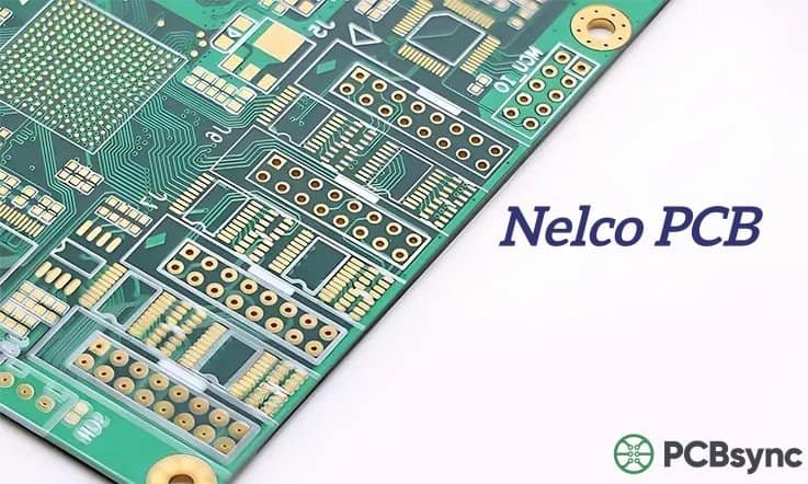
If you’ve spent any time designing high-speed digital circuits or RF applications, you’ve probably encountered situations where standard FR-4 just doesn’t cut it. Signal integrity issues, thermal management problems, or reliability concerns during lead-free assembly—these challenges push us toward better materials. That’s where Nelco PCB materials come into the picture.
Nelco (now part of AGC Multi Material) has been manufacturing high-performance PCB laminates for over 50 years. Their materials have become the go-to choice for engineers working on telecommunications infrastructure, automotive electronics, aerospace systems, and medical devices. In this guide, I’ll walk you through everything you need to know about Nelco PCB materials—from the technical specifications to real-world applications.
A Nelco PCB is a printed circuit board fabricated using Nelco’s proprietary laminate and prepreg materials. Unlike generic FR-4, Nelco materials are engineered for specific performance requirements—whether that’s maintaining signal integrity at 10 GHz, surviving multiple lead-free reflow cycles, or operating reliably in harsh automotive environments.
The key difference lies in the resin systems and glass reinforcement that Nelco uses. While standard FR-4 relies on basic epoxy formulations, Nelco materials employ modified epoxy systems, BT (bismaleimide triazine), polyimide, and cyanate ester chemistries to achieve superior electrical and thermal properties.
Key Characteristics That Set Nelco Apart
Glass Transition Temperature (Tg): Most Nelco materials exceed 170°C, with some reaching above 210°C—essential for lead-free assembly processes
Low Dielectric Constant (Dk): Values ranging from 3.5 to 4.5, enabling faster signal propagation
Low Dissipation Factor (Df): Typically under 0.015, minimizing signal loss in high-frequency applications
RoHS Compliance: All Nelco materials meet environmental regulations
Nelco PCB Calculator
PCBSync Engineering Tools
N4000-13 Properties
Dielectric Constant (Dk)
4.5
Dissipation Factor (Df)
0.020
Tg (Glass Transition)
180°C
Td (Decomposition)
340°C
CTI (Tracking Index)
≥600V
Flammability
UL 94 V-0
Best Applications:
General purpose multilayer PCBs, industrial control, consumer electronics, telecommunications equipment.
Quick Material Comparison
Material
Dk
Df
Tg
Application
N4000-13
4.5
0.020
180°C
General Purpose
N4000-13 SI
4.2
0.013
175°C
Signal Integrity
N4000-29
3.9
0.010
200°C
High-Speed Digital
N4350-13 RF
3.5
0.008
280°C
RF/Microwave
N7000-2 HT
4.3
0.014
260°C
High Temperature
Microstrip Impedance Calculator
Calculated Impedance
50.2 Ω
Trace Width Finder
Required Trace Width
6.1 mil
⚠️ Results are approximations. Always verify with your PCB manufacturer’s impedance calculator for production.
Stack-Up Generator
Recommended Stack-Up
4-Layer N4000-13 (1.6mm)
L1 – Signal/Component1 oz Cu
Prepreg – 4 mil
L2 – Ground Plane1 oz Cu
Core – 47 mil
L3 – Power Plane1 oz Cu
Prepreg – 4 mil
L4 – Signal/Component1 oz Cu
Total Thickness:1.6 mm (63 mil)
Controlled Impedance:50Ω microstrip on L1/L4
Manufacturing Cost Estimator
×
Unit Price
$12.50
Total Cost
$125.00
Lead Time
7-10 days
Note: This is an estimate only. Actual pricing depends on design complexity, DFM requirements, and current material availability. Contact PCBSync for accurate quotation.
Choose Nelco material based on signal speed requirements. Use N4000-13 for general applications, N4000-13 SI for high-speed digital (>2.5Gbps), N4350-13 RF for RF designs above 1GHz, and N7000-2 HT for high-temperature environments (>150°C operating).
2
Controlled Impedance Design
For Nelco materials, account for Dk variation with frequency. N4000-13 SI has stable Dk from 1MHz-10GHz. Use manufacturer-provided Dk values at your target frequency. Include ±10% impedance tolerance in specifications.
3
Layer Stack-Up Best Practices
Maintain symmetrical stack-up to prevent warpage. Place high-speed signals adjacent to ground planes. Use N4000-13 EP prepreg for mixed material builds. Ensure consistent core/prepreg Dk values throughout the stack.
4
DFM Guidelines for Nelco
Minimum drill size: 8 mil for N4000-13, 10 mil for RF materials. Annular ring: 5 mil minimum. Copper to edge clearance: 10 mil. Via aspect ratio: 10:1 max for reliable plating. Allow 10% panel utilization loss for material handling.
5
Thermal Management
Nelco materials have good thermal conductivity (~0.4 W/mK). For high-power designs, use thermal vias (0.3mm diameter, 1mm pitch) under components. Consider heavy copper (2-3 oz) for power planes. N7000-2 HT recommended for >150°C applications.
!
Important Consideration
Nelco materials may have longer lead times than standard FR-4. Plan 2-3 weeks additional time for material procurement. Contact PCBSync early in your design cycle for material availability and alternative recommendations.
Nelco offers an extensive portfolio of materials, each optimized for specific applications. Understanding these options helps you select the right material for your design requirements.
N4000 Series: The Workhorse Family
The N4000 series represents Nelco's most versatile product line, suitable for everything from high-speed digital circuits to RF applications operating in the 1-10 GHz range.
Material
Tg (°C)
Dk/Df @1GHz
Best For
N4000-6
175
4.3 / 0.023
General high-Tg applications
N4000-7
155
4.0 / 0.018
Low CTE, lead-free assembly
N4000-13
>210
3.7 / 0.009
High-speed digital, 1-10 GHz
N4000-13 SI
>210
3.6 / 0.008
Signal integrity critical apps
N4000-29
185
4.3 / 0.018
Automotive, lead-free focus
Pro Tip: The N4000-13 series has become the industry standard for demanding high-speed/low-loss designs. If you're designing backplanes or high-layer-count boards, this should be your starting point.
Meteorwave Series: Ultra-Low Loss Performance
When standard high-performance materials aren't enough, the Meteorwave family delivers extremely low loss characteristics for the most demanding applications—think 100Gbps core routers, supercomputers, and 5G infrastructure.
Material
Dk @10GHz
Df @10GHz
Applications
Meteorwave 1000 NF
3.4
0.003
No-flow applications
Meteorwave 8000
3.28
0.0016
56-112 Gbps systems
Meteorwave 8300
3.0
0.0017
RF/Microwave, satellites
Meteorwave 8350
3.5
0.0018
Controlled Dk designs
Benefits of Using Nelco PCB Materials
Why should you consider Nelco materials over standard FR-4 or even other high-performance alternatives? Here's what I've found matters most in real-world applications:
Superior Signal Integrity
The low Dk and Df values of Nelco materials translate directly to faster signal propagation and reduced signal loss. For high-frequency designs operating in the 1-10 GHz range, this can mean the difference between a working prototype and weeks of debugging signal integrity issues.
The N4000-13 SI variant specifically uses special glass fabric that provides enhanced electrical performance for impedance-critical applications. When you need precise impedance control, this material delivers.
Excellent Thermal Performance
With Tg values exceeding 210°C for many products, Nelco materials handle lead-free assembly processes without breaking a sweat. The materials are rated for reflow temperatures up to 260°C, depending on design and construction—giving you plenty of margin for manufacturing.
The low Z-axis coefficient of thermal expansion (CTE) also means better reliability during thermal cycling—particularly important for automotive and aerospace applications where temperature swings are common.
Long-Term Reliability
Conductive Anodic Filament (CAF) resistance is one of the most overlooked specifications in PCB material selection. CAF failures occur when moisture enables copper migration between conductors, causing shorts. Nelco materials are specifically engineered to resist CAF formation, with testing showing resistance exceeding 500 hours under accelerated conditions.
For medical devices, automotive systems, or any application where field failures aren't acceptable, this reliability advantage is substantial.
Processing Compatibility
One of the practical advantages of Nelco materials is that they process similarly to traditional high-Tg FR-4. Your fabricator doesn't need special equipment or completely new process windows—they can use established procedures with minor adjustments. This means shorter lead times and fewer yield issues during PCB manufacturing.
This is probably the most common question I hear from engineers: which material should I use? The answer depends on your specific requirements.
Parameter
Standard FR-4
Nelco N4000-13
Rogers 4003C
Frequency Range
< 1 GHz
1-10 GHz
> 10 GHz
Dk
4.2-4.5
3.6-3.7
3.38
Df
0.020-0.025
0.008-0.009
0.0027
Tg
130-140°C
> 210°C
> 280°C
Cost
1x (baseline)
2-3x
5-10x
Processing
Standard
Similar to FR-4
Special handling
When to Use Each Material
Choose FR-4 when:
Your design operates below 1 GHz
Cost is the primary concern
Thermal requirements are modest (no lead-free assembly)
Choose Nelco when:
Operating frequency is 1-10 GHz
Lead-free assembly compatibility is required
Long-term reliability is critical
You need better performance than FR-4 without Rogers cost
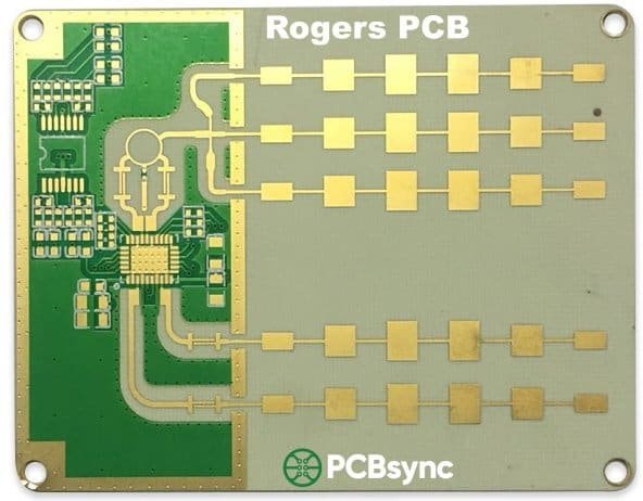
Choose Rogers when:
Operating frequency exceeds 10 GHz
RF/microwave applications require lowest possible loss
Performance requirements justify the cost premium
Nelco PCB Applications by Industry
Nelco materials have found their way into nearly every high-performance electronics sector. Here's where they excel:
Telecommunications & 5G Infrastructure
Base stations, remote radio heads, and millimeter-wave modules increasingly rely on Nelco's low-loss laminates. The Meteorwave series, in particular, supports the high data rates (56-112 Gbps) required for modern network infrastructure. With 5G deployment accelerating globally, demand for these materials continues to grow.
Automotive Electronics
Modern vehicles contain dozens of ECUs, radar sensors, and communication modules. The N4000-13SI provides stable performance in the harsh under-hood environment (temperatures up to 155°C), while the N4000-29 is specifically optimized for automotive applications requiring lead-free assembly compatibility. ADAS systems, in particular, benefit from Nelco's consistent electrical properties.
Aerospace & Defense
Mission-critical systems demand the highest reliability. Nelco's N4800-6 offers excellent dimensional stability for avionics, while the halogen-free N4800-6HF variant meets stringent safety requirements. Military and defense applications also benefit from Nelco's proven CAF resistance.
Medical Electronics
Imaging systems, patient monitors, and diagnostic equipment require both reliability and consistent electrical performance. Nelco materials deliver on both counts, with the added benefit of RoHS compliance for environmental safety.
High-Performance Computing
Supercomputers, data center switches, and high-speed routers push the boundaries of signal integrity. The Meteorwave 8000, designed for 100+ Gbps applications, has become a standard choice for these demanding environments.
Design Considerations for Nelco PCB
Working with Nelco materials requires attention to several design factors:
Stack-Up Design
The stack-up directly impacts signal transmission, power delivery, and long-term reliability. For high-speed designs, work closely with your fabricator to optimize the layer arrangement. Consider using SI glass variants for impedance-critical layers.
Material Loss Considerations
Total signal loss includes contributions from skin effect, dielectric loss (loss tangent), fiberglass composition, and conductor surface roughness. When selecting materials, consider all these factors—not just the datasheet Df value.
Via Selection
For multilayer Nelco boards, via selection becomes critical. Consider the aspect ratio (PCB thickness vs. hole diameter), plating requirements, and annular ring specifications per IPC Class 2 or Class 3 requirements. A 10 mil via typically reduces to 7 mil after plating.
Surface Finishes for Nelco PCB
The surface finish affects solderability, shelf life, and high-frequency performance. Here are the common options:
Finish
Characteristics
Best For
ENIG
Gold over nickel barrier; excellent solderability
Most applications
Immersion Tin
Chemical tin deposition; good for fine pitch
High-speed signals
Immersion Silver
No nickel layer; requires special storage
RF applications
HASL
Hot air solder leveling; uniform thickness
Aerospace/military
Hard Gold
Gold over nickel; highly durable
Edge connectors
Frequently Asked Questions
1. What is the difference between Nelco and standard FR-4?
While both are glass-reinforced epoxy laminates, Nelco materials use enhanced resin systems that provide higher Tg (>210°C vs. 130-140°C for standard FR-4), lower dielectric loss, and better CAF resistance. These improvements enable reliable operation at higher frequencies and temperatures, making Nelco suitable for applications where standard FR-4 would fail.
2. Can Nelco PCB handle lead-free assembly?
Yes. All Nelco materials are designed for RoHS-compliant, lead-free assembly processes. Most materials are rated for reflow temperatures up to 245°C, with some (like N4000-13 EP) supporting up to 260°C depending on the board design and construction. This makes them fully compatible with modern lead-free soldering requirements.
3. Is Nelco more expensive than Rogers?
Generally, Nelco materials cost less than Rogers—typically 2-3x the price of standard FR-4, compared to 5-10x for Rogers materials. This cost advantage, combined with processing similar to standard FR-4, makes Nelco an attractive middle-ground option for applications that need better performance than FR-4 but don't require Rogers-level specifications.
4. What industries use Nelco PCB materials most?
Telecommunications and 5G infrastructure lead the demand, followed by automotive electronics (particularly ADAS systems), aerospace and defense, medical devices, and high-performance computing. Any application requiring reliable operation at 1-10 GHz, lead-free assembly compatibility, or long-term reliability is a candidate for Nelco materials.
5. How do I specify Nelco material in my Gerber files?
Include the specific Nelco material designation (e.g., N4000-13 SI, Meteorwave 8000) in your fabrication notes or README file. Specify the required stack-up, including dielectric thicknesses, copper weights, and surface finish. Also note any impedance control requirements. Work with your fabricator early in the design process to ensure material availability and optimize the stack-up for manufacturability.
Additional Resources
For further information and technical specifications, consult these resources:
AGC Multi Material Official Site – Product datasheets, technical specifications, and material selector guides
IPC-4101 Standard – Industry specification for base materials, including slash sheets for Nelco products
IPC-2221/2222 – PCB design standards applicable to high-performance materials
Nelco N4000-13 Best Practices Document – Processing recommendations from the manufacturer
Your PCB Fabricator – Always consult with your fabricator on material availability and processing capabilities
Conclusion
Nelco PCB materials occupy a sweet spot in the high-performance laminate market—offering significantly better electrical and thermal performance than standard FR-4, while remaining more cost-effective and easier to process than premium Rogers materials. For engineers working on telecommunications equipment, automotive systems, or any application operating in the 1-10 GHz range, Nelco materials deserve serious consideration.
The key is matching the material to your specific requirements. Don't over-specify (and overpay) if your application doesn't need it, but don't underestimate the value of reliability and signal integrity for demanding applications. With over 50 years of proven performance and global availability, Nelco materials have earned their reputation as the engineer's choice for high-performance PCB design.
Have questions about selecting the right Nelco material for your design? Reach out to your PCB fabricator or contact AGC Multi Material directly—they have technical support teams ready to help optimize your design.
Inquire: Call 0086-755-23203480, or reach out via the form below/your sales contact to discuss our design, manufacturing, and assembly capabilities.
Quote: Email your PCB files to Sales@pcbsync.com (Preferred for large files) or submit online. We will contact you promptly. Please ensure your email is correct.
Notes: For PCB fabrication, we require PCB design file in Gerber RS-274X format (most preferred), *.PCB/DDB (Protel, inform your program version) format or *.BRD (Eagle) format. For PCB assembly, we require PCB design file in above mentioned format, drilling file and BOM. Click to download BOM template To avoid file missing, please include all files into one folder and compress it into .zip or .rar format.


