Inquire: Call 0086-755-23203480, or reach out via the form below/your sales contact to discuss our design, manufacturing, and assembly capabilities.
Quote: Email your PCB files to Sales@pcbsync.com (Preferred for large files) or submit online. We will contact you promptly. Please ensure your email is correct.
Notes: For PCB fabrication, we require PCB design file in Gerber RS-274X format (most preferred), *.PCB/DDB (Protel, inform your program version) format or *.BRD (Eagle) format. For PCB assembly, we require PCB design file in above mentioned format, drilling file and BOM. Click to download BOM template To avoid file missing, please include all files into one folder and compress it into .zip or .rar format.
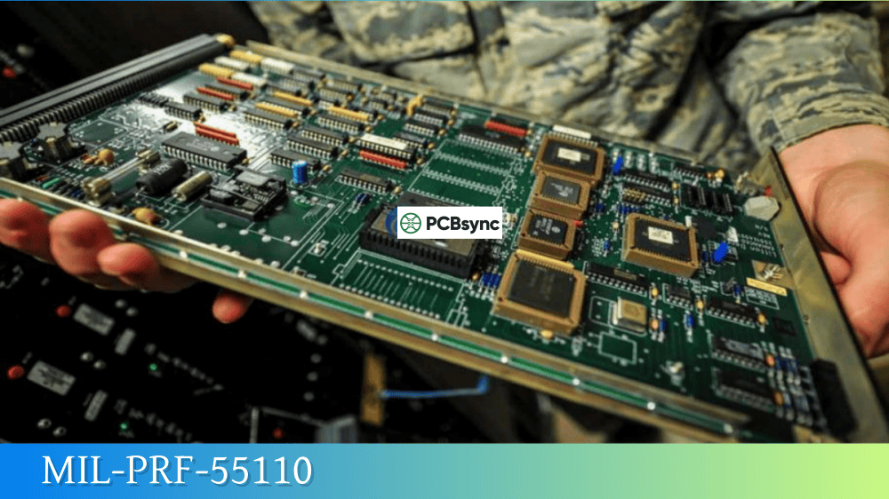
MIL-PRF-55110: Understanding Rigid Military PCB Specifications
As a PCB engineer who has worked with defense contractors for over a decade, I can tell you that navigating military specifications isn’t for the faint of heart. Among the alphabet soup of MIL-specs, MIL-PRF-55110 stands out as the foundational standard for rigid printed wiring boards in defense applications. Whether you’re a design engineer trying to understand qualification requirements or a procurement officer sourcing compliant boards, this guide breaks down everything you need to know about this critical specification.
MIL-PRF-55110 is a U.S. Department of Defense (DoD) performance specification that establishes qualification and performance requirements for rigid single-sided, double-sided, and multilayer printed wiring boards (PWBs) with or without plated-through holes. Administered by the Defense Logistics Agency (DLA) Land and Maritime division, this specification ensures that PCBs used in military equipment meet stringent reliability standards.
The specification’s full title is “Printed Wiring Board, Rigid, General Specification For,” and it applies to boards intended for ground support, airborne, and shipboard electronic equipment. The goal? Eliminate high-density hand wiring while enabling compact electronic packaging for mission-critical systems.
Current Status of MIL-PRF-55110
Here’s something that catches many engineers off guard: MIL-PRF-55110 has been marked “Inactive for New Design” since December 31, 1997. For new designs, the DoD directs manufacturers to use MIL-PRF-31032 instead. However—and this is important—the specification remains very much alive for legacy programs.
The current revision is MIL-PRF-55110J with Amendment 1, dated September 25, 2023. The DLA continues to maintain the Qualified Products List (QPL-55110) for manufacturers who support legacy military systems that still reference this specification.
MIL-PRF-55110 Board Types and Classifications
The specification categorizes rigid PCBs into three primary types based on their construction:
Type
Description
Typical Applications
Type 1
Single-sided printed wiring board
Simple circuits, power distribution
Type 2
Double-sided printed wiring board
Moderate complexity, through-hole components
Type 3
Multilayer printed wiring board
High-density designs, complex signal routing
Type 3 qualification extends to cover Type 1 and Type 2 boards automatically. Similarly, Type 2 qualification extends to cover Type 1. This hierarchical structure simplifies the qualification process for manufacturers building diverse product lines.
Base Material Designators
MIL-PRF-55110 references specific base material types identified by designator codes. Understanding these codes is essential when reviewing QPL listings or master drawings:
Material selection drives thermal performance, dielectric properties, and overall reliability in demanding environments. Your master drawing should specify the appropriate designator based on the application’s environmental requirements.
Understanding the QPL and QML Programs
One of the most confusing aspects of MIL-PRF-55110 involves its dual product assurance pathways. Let me clarify the difference.
Qualified Products List (QPL) Program
The traditional QPL program, detailed in Appendix A of the specification, requires manufacturers to:
Submit qualification test specimens to a government-acceptable laboratory
Undergo verification inspection of production processes
Maintain qualification through periodic requalification (every two years)
Appear on QPL-55110 to supply compliant products
The qualifying activity responsible for QPL-55110 is the Defense Supply Center Columbus (DSCC-VQE). Manufacturers receive a Qualification Reference Number (QRN) with an embedded expiration date in the format “mmddyy.”
Qualified Manufacturers List (QML) Program
Appendix B offers an alternative path through the QML program of MIL-PRF-31032. Here’s where things get interesting for modern manufacturers: if you’re certified to MIL-PRF-31032, you can use your QML-certified Technical Review Board (TRB) approved processes to meet MIL-PRF-55110 requirements.
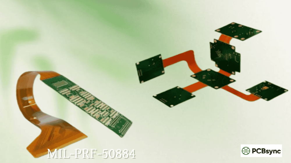
This “twist” means one certification effectively covers three specifications—MIL-PRF-31032, MIL-PRF-55110 (rigid), and MIL-PRF-50884 (flexible). For the certificate of conformance, you simply state: “Product was manufactured to meet MIL-PRF-55110J Amendment 1, Appendix B, acceptable requirements.”
Program
Approach
Expiration
Listed On
QPL (Appendix A)
Traditional qualification testing
Yes (2 years)
QPL-55110
QPL/QML (Appendix B)
MIL-PRF-31032 TRB processes
No
QML-31032
Key Technical Requirements in MIL-PRF-55110
Let me walk through the critical technical requirements that separate military-grade boards from commercial products.
Plated-Through Hole Requirements
For Type 2 and Type 3 boards, plated-through holes (PTH) must meet specific criteria:
Annular Ring: The minimum annular ring for functional internal lands on multilayer boards is specified in the master drawing. This is where military specs get significantly tighter than commercial standards—IPC Class 3 requires 0.002″ minimum, while MIL specs often demand larger margins.
Conductor Thickness: When a copper foil weight requirement is specified, MIL-PRF-55110 allows up to 10% reduction below the minimum allowable foil thickness to accommodate chemical or mechanical cleaning processes.
Dielectric Layer Thickness: The minimum separation between conductor layers must meet the master drawing specifications. This directly impacts voltage breakdown and reliability.
Electrical Test Requirements
Electrical testing under MIL-PRF-55110 follows stringent parameters:
Parameter
Requirement
Continuity
Less than 10 Ω
Isolation
Greater than 2 MΩ (up to 10 MΩ for stringent requirements)
Test Voltage
Minimum 40 volts unless otherwise specified
These tests must be performed on every production lot, with additional monthly testing on thermally stressed cross-sections in both X and Y directions.
Inspection and Testing Groups
The specification organizes testing into distinct groups:
In-Process Inspection: Performed during manufacturing to catch defects early.
Group A Inspection: Applied to production boards using C=0 sampling plans, covering visual and dimensional requirements.
Qualification Testing: Performed at a government-acceptable laboratory on qualification test specimens (minimum of six specimens, serialized 1 through 6).
MIL-PRF-55110 vs. MIL-PRF-31032: Key Differences
Engineers often ask me when to use which specification. Here’s my practical guidance:
Aspect
MIL-PRF-55110
MIL-PRF-31032
Status
Legacy (inactive for new design)
Current specification
Scope
Rigid PCBs only
All PCB types (rigid, flex, rigid-flex)
Qualification
QPL-based or through 31032
QML-based
New Programs
Not applicable
Required for new designs
Legacy Support
Still maintained
Full support
If you’re starting a new design today, MIL-PRF-31032 is your specification. However, if you’re supporting an existing program with drawings that reference MIL-PRF-55110, you’ll need to maintain compliance with that specification—either through direct QPL certification or through the Appendix B QML pathway.
MIL-PRF-55110 vs. IPC Class 3: Understanding the Relationship
Commercial aerospace and high-reliability applications often reference IPC-6012 Class 3 instead of military specifications. Here’s how they compare:
Requirement
MIL-PRF-55110
IPC-6012 Class 3
Annular Ring (External)
Larger minimum required
0.002″ minimum
Copper Thickness After Processing
Not defined post-process
Minimum specified
Solder Coating Thickness
Stricter requirements
Standard requirements
Defect Rejection (Measling, Crazing)
Strict rejection
May be accepted
Qualification Process
DLA-administered QPL/QML
Manufacturer-customer agreement
Ongoing Audits
Required by DLA
Per customer requirements
IPC-6013 Class III (C) is accepted by government agencies as a commercial off-the-shelf (COTS) equivalent of MIL-PRF-31032 for flexible boards. This recognition has helped streamline procurement for some programs.
Typical Military PCB Applications
Boards manufactured to MIL-PRF-55110 find their way into demanding applications including:
Command and Control Systems
Airborne Warning and Control Systems (AWACS)
Guidance and Targeting Systems
Electronic Warfare Equipment
Surveillance and Communication Devices
Military Navigation Equipment
Power Converters for Missile Systems
Radar Systems
These applications share common requirements: operation in extreme temperatures (from arctic to desert conditions), resistance to vibration and mechanical shock, and zero tolerance for field failures.
Environmental and Reliability Considerations
Military PCBs face environments that would destroy commercial boards in hours. MIL-PRF-55110 addresses this through:
Temperature Extremes: Materials must maintain properties from -65°C to +125°C or higher, depending on the specified grade.
Thermal Cycling: Boards undergo repeated thermal stress testing to verify plated-through hole integrity and laminate stability.
Vibration and Shock: Design guidelines recommend low aspect ratios (10:1 or lower), symmetric stackups, and uniform copper distribution to minimize the effects of mechanical stress.
Humidity and Corrosion: Conformal coatings and appropriate surface finishes (ENIG, hard gold) protect against environmental degradation.
When delivering compliant boards, your certificate of conformance must include:
Manufacturer’s name and address
Customer’s name and address
Specification reference (MIL-PRF-55110J Amendment 1, Appendix A or B)
Board type and base material designator
Lot identification and traceability information
Statement of compliance
Deviations fall into two categories: additive (tighter requirements or additional tests) and negative (looser requirements or eliminated tests). Additive deviations don’t affect compliance certification; negative deviations do, and must be explicitly approved.
How to Find Qualified Suppliers
The DLA maintains the official QPL-55110 database, which you can access through their Qualified Products Database (QPD). When searching for suppliers, look for:
Current qualification status (check expiration dates in the QRN)
Material types covered by their qualification
Board types qualified (Type 1, 2, or 3)
Etchback capability (indicated by asterisk in QRN)
QML-31032 cross-qualification (indicated by exclamation mark)
Many qualified suppliers also hold AS9100 certification for aerospace quality management, which provides additional assurance for mission-critical applications.
Useful Resources and Download Links
For engineers and procurement professionals working with MIL-PRF-55110, here are the essential resources:
The official specification PDF is available for free download from the DLA portal. Commercial document services also offer copies, typically for a nominal fee.
Frequently Asked Questions About MIL-PRF-55110
Can I still get qualified to MIL-PRF-55110 directly?
No, you cannot obtain new direct QPL certification to MIL-PRF-55110. Since December 1997, new manufacturers must qualify through MIL-PRF-31032 and then use Appendix B of MIL-PRF-55110 to certify products for legacy programs. Existing QPL listings continue to be maintained for manufacturers who held qualification before that date.
My drawing references MIL-P-55110. Is that the same specification?
MIL-P-55110 was the earlier “slash sheet” version that preceded the performance-based MIL-PRF-55110. If your drawing references MIL-P-55110D or earlier, it may predate modern QPL requirements. Contact the design authority to determine if the drawing should be updated to reference the current specification.
What is the difference between QPL and QML certification?
QPL (Qualified Products List) is product-focused—specific products are tested and qualified. QML (Qualified Manufacturers List) is process-focused—a manufacturer’s entire quality management system and processes are qualified, allowing them to produce any product within their certified technology scope. QML offers more flexibility but requires maintaining a Technical Review Board (TRB) and ongoing DLA audits.
Does MIL-PRF-55110 apply to flexible or rigid-flex boards?
No. MIL-PRF-55110 covers rigid boards only. For flexible and rigid-flex printed wiring boards, reference MIL-PRF-50884. The umbrella specification MIL-PRF-31032 covers all board types (rigid, flex, and rigid-flex) and is preferred for new designs.
How often must manufacturers requalify under MIL-PRF-55110?
Under the traditional QPL program (Appendix A), qualifications are validated every two years. The expiration date is embedded in the Qualification Reference Number. Manufacturers using the QML pathway (Appendix B) through MIL-PRF-31032 do not have expiration dates on their 55110 qualification, but must maintain their QML status through ongoing TRB reviews and DLA audits.
Final Thoughts
Working with MIL-PRF-55110 requires understanding both the specification itself and its relationship to the broader military qualification ecosystem. While the specification is technically “inactive for new design,” it remains essential for the vast installed base of military equipment that will be maintained for decades to come.
For new programs, invest the time to get certified to MIL-PRF-31032—it provides coverage for rigid, flexible, and rigid-flex boards under one qualification umbrella. For legacy support, ensure your manufacturer holds current QPL-55110 status or maintains Appendix B compliance through their QML-31032 certification.
The military’s slow pace of change means MIL-PRF-55110 knowledge will remain valuable for years. Take the time to understand the specification thoroughly, and you’ll be prepared to navigate both legacy support and new program requirements with confidence.
Inquire: Call 0086-755-23203480, or reach out via the form below/your sales contact to discuss our design, manufacturing, and assembly capabilities.
Quote: Email your PCB files to Sales@pcbsync.com (Preferred for large files) or submit online. We will contact you promptly. Please ensure your email is correct.
Notes: For PCB fabrication, we require PCB design file in Gerber RS-274X format (most preferred), *.PCB/DDB (Protel, inform your program version) format or *.BRD (Eagle) format. For PCB assembly, we require PCB design file in above mentioned format, drilling file and BOM. Click to download BOM template To avoid file missing, please include all files into one folder and compress it into .zip or .rar format.


