Inquire: Call 0086-755-23203480, or reach out via the form below/your sales contact to discuss our design, manufacturing, and assembly capabilities.
Quote: Email your PCB files to Sales@pcbsync.com (Preferred for large files) or submit online. We will contact you promptly. Please ensure your email is correct.
Notes: For PCB fabrication, we require PCB design file in Gerber RS-274X format (most preferred), *.PCB/DDB (Protel, inform your program version) format or *.BRD (Eagle) format. For PCB assembly, we require PCB design file in above mentioned format, drilling file and BOM. Click to download BOM template To avoid file missing, please include all files into one folder and compress it into .zip or .rar format.
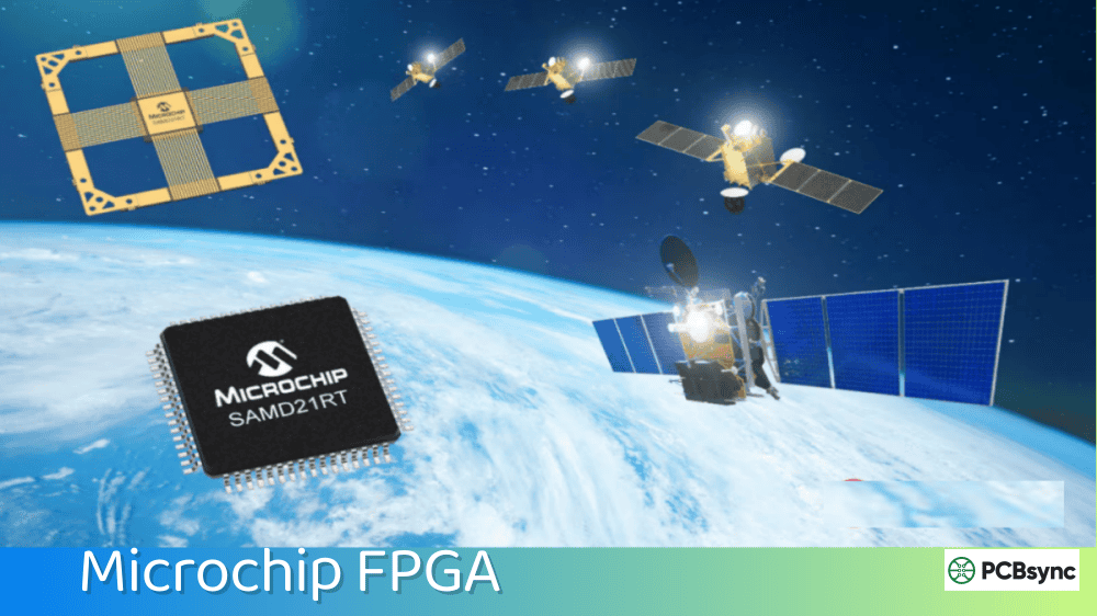
If you have spent any time designing electronics for space, aerospace, or high-reliability defense systems, you know the challenge: finding programmable logic that will not fail when hit by cosmic radiation or sophisticated cyber attacks. After working with various FPGA families over the years, I have come to appreciate what Microchip FPGA solutions – specifically the former Microsemi portfolio – bring to the table for mission-critical applications.
This guide covers everything you need to know about Microchip radiation-tolerant and secure FPGA families, from the legacy RTAX antifuse devices to the latest RT PolarFire SoC FPGAs. Whether you are designing satellite payloads, avionics systems, or nuclear plant controls, understanding these devices can save you months of development time and prevent costly mission failures.
Understanding Microchip FPGA Technology for Harsh Environments
Microchip Technology acquired Microsemi Corporation in May 2018, inheriting over 60 years of space flight heritage. This was not just a business acquisition – it brought together two companies with deep expertise in radiation-hardened semiconductors. Today, Microchip FPGA products represent some of the most trusted programmable logic devices for space and defense applications worldwide.
What makes these devices special? Unlike commercial FPGAs that use SRAM-based configuration memory (which is highly susceptible to radiation-induced bit flips), Microchip radiation-tolerant FPGAs use non-volatile technologies – antifuse, Flash, and SONOS – that are inherently immune to Single Event Upsets (SEUs) in their configuration memory. This means no external scrubbing circuits, no constant monitoring, and no Triple Module Redundancy (TMR) overhead just to keep your design running.
Key Microchip FPGA Families for Radiation-Tolerant Applications
Microchip offers the most comprehensive portfolio of radiation-tolerant FPGAs in the industry. Each family targets specific application requirements, from simple command-and-control functions to complex signal processing and AI/ML workloads.
RT PolarFire FPGA: The Latest Generation for Space
The RT PolarFire represents the cutting edge of Microchip FPGA technology for space applications. Built on 28nm SONOS technology, these devices deliver up to 481,000 logic elements, 33 Mb of embedded SRAM, 1,480 DSP blocks, and 24 lanes of 10 Gbps transceivers – all while consuming up to 50% less power than competing SRAM-based FPGAs.
Key RT PolarFire specifications:
Configuration memory immune to SEUs (no scrubbing required)
Total Ionizing Dose (TID) tolerance beyond 100 kRads
Single Event Latch-up (SEL) immunity to LET > 104 MeV.cm2/mg
QML Class Q qualified (RTPF500ZT), with path to QML Class V
The RT PolarFire SoC FPGA is genuinely groundbreaking – it is the industry first radiation-tolerant FPGA with an embedded, real-time, Linux-capable RISC-V microprocessor subsystem. This opens up entirely new possibilities for satellite processing, where you need both the flexibility of a processor for software updates and the deterministic performance of FPGA fabric for real-time tasks.
The quad-core, 64-bit RISC-V processor can run Linux for complex algorithms while the FPGA fabric handles high-speed I/O and DSP functions. Engineering samples are available now, with a roadmap to QML Class V and Class Y qualification.
RTG4 FPGA: Proven Flight Heritage
The RTG4 family has been the workhorse of high-speed signal processing in space for years. Built on 65nm Flash technology, these devices offer up to 151,824 registers hardened against SEUs, along with 24 lanes of 3.125 Gbps SerDes for high-speed communications.
RTG4 FPGAs achieved QML Class V qualification in 2018 – the highest qualification level for space components – and have proven flight heritage on missions including Mission Extension Vehicles (MEV) 1 and 2, and the Korean CAS-500 satellite.
RTAX Antifuse FPGAs: Ultimate Reliability
When absolute reliability matters more than reprogrammability, RTAX antifuse FPGAs remain the gold standard. These one-time-programmable devices have flight heritage on some of the most critical space missions ever flown, including the James Webb Space Telescope, Galileo navigation constellation, GPS III, and the Iridium satellite network.
The RTAX-DSP variants include up to 120 embedded 18×18 multiply-accumulate blocks capable of 15 billion MACs per second at 125 MHz across the full military temperature range (-55C to 125C).
Microchip FPGA Family Comparison: Radiation-Tolerant Solutions
Selecting the right Microchip FPGA for your application requires understanding the trade-offs between logic density, power consumption, radiation performance, and qualification level. The following table summarizes key specifications across the radiation-tolerant portfolio:
FPGA Family
Technology
Max Logic
SerDes
Qualification
Reprogram
RT PolarFire
28nm SONOS
481K LEs
24x 10 Gbps
QML Q/V path
Yes
RT PolarFire SoC
28nm SONOS
460K LEs
24x 10 Gbps
QML V/Y path
Yes
RTG4
65nm Flash
150K LEs
24x 3.125 Gbps
QML Class V
Yes
RTAX-S/SL
Antifuse
4M gates
N/A
QML Class V
No (OTP)
RTAX-DSP
Antifuse
1.5M gates
N/A
QML Class V
No (OTP)
Note: LEs = Logic Elements; OTP = One-Time Programmable; QML = Qualified Manufacturers List
Security is not optional anymore – it is a fundamental requirement. Microchip FPGA devices, particularly the PolarFire family, integrate what I would argue is the most comprehensive security architecture available in any FPGA today. The UK National Cyber Security Centre (NCSC) has reviewed the PolarFire FPGA Single-Chip Crypto Design Flow against their stringent requirements, which tells you something about the level of rigor that went into the design.
Design Security: Protecting Your Intellectual Property
Every Microchip FPGA with security features includes multiple layers of design protection:
Physically Unclonable Functions (PUFs): Each device has a unique silicon fingerprint that cannot be cloned or extracted, used for cryptographic key storage
Secure Non-Volatile Memory (sNVM): 56 KB of encrypted storage for application keys and sensitive data, protected by PUF-derived keys
Encrypted Bitstream: AES-256 encryption prevents reverse engineering of your design during programming and in the field
Anti-Tamper Features: Voltage monitors, temperature sensors, clock glitch detectors, and mesh sensors detect physical attacks
Secure Boot: Cryptographic verification ensures only authenticated firmware runs on the device
Data Security: The Athena User Crypto Processor
For data security applications, PolarFire S grade devices include a dedicated hardware cryptoprocessor – the Athena TeraFire EXP-F5200B. This is not a soft-core IP block that consumes your logic resources; it is hardened silicon running at 189 MHz with built-in resistance to Side-Channel Attacks (SCA).
Supported algorithms include:
AES-128/192/256 (ECB, CBC, CTR, GCM modes)
SHA-256, SHA-384, SHA-512
RSA-2048/3072/4096
ECDSA/ECDH with P-256, P-384, P-521 curves
HMAC
True Random Number Generator (TRNG) with NIST SP 800-90B compliance
The crypto processor is compliant with Commercial National Security Algorithm (CNSA) suite requirements, making these devices suitable for government and defense applications requiring the highest levels of data protection.
Radiation Performance Specifications
Understanding radiation performance specifications is critical for mission planning. Here is a detailed breakdown of how Microchip FPGA devices perform under radiation:
Parameter
RT PolarFire
RTG4
RTAX
TID Tolerance
>100 kRad(Si)
>100 kRad(Si)
300 kRad(Si)
SEL Immunity
>104 MeV.cm2/mg
>103 MeV.cm2/mg
>120 MeV.cm2/mg
Config SEU Immunity
Immune
Immune
Immune
Register SEU
Hardened by design
Hardened by design
Hardened by design
SRAM Protection
SECDED EDAC
SECDED EDAC
EDAC
TID = Total Ionizing Dose; SEL = Single Event Latch-up; SEU = Single Event Upset; SECDED = Single Error Correct Double Error Detect
Libero SoC Design Suite: Microchip FPGA Development Tools
All Microchip FPGA development starts with Libero SoC Design Suite. It is a complete integrated environment that takes you from RTL entry through synthesis, place-and-route, timing analysis, and device programming. Version 2025.1 introduced a unified installer that bundles everything you need in one package.
Key Development Features
Synopsys Synplify Pro Synthesis: Industry-standard synthesis engine optimized for Microchip architectures
Siemens ModelSim/QuestaSim: Integrated simulation with full visibility into design behavior
SmartHLS Compiler: High-level synthesis from C/C++ for faster algorithm implementation
SmartDebug: Real-time debugging through JTAG with live probe access to internal signals
TMR Synthesis Support: Optional Triple Module Redundancy for additional radiation mitigation in control circuits
Secure Production Programming: FIPS 140-2 Level 3 HSM support for secure device provisioning
IP Core Library for Microchip FPGA Designs
Microchip provides an extensive library of pre-verified IP cores specifically optimized for their FPGA architectures. For space applications, you will find cores for SpaceWire, MIL-STD-1553, CCSDS protocols, and more. The Mi-V ecosystem provides comprehensive RISC-V development support for PolarFire SoC designs, including Linux BSPs and real-time operating systems.
Understanding QML Qualification Levels for Microchip FPGA
If you are new to space-grade components, the qualification levels can seem confusing. Here is what you actually need to know:
QML Level
Description
Typical Applications
Class V
Highest qualification. 100% screening with extensive environmental testing.
Critical deep-space missions, interplanetary probes, Class 1 spacecraft
Class Q
High reliability. Reduced screening but same radiation-tolerant silicon.
LEO/MEO satellites, launch vehicles, military aircraft
Class B
MIL-STD-883 testing. Good for development and lower-risk missions.
New Space constellations, prototype systems
Sub-QML
Same RT silicon with reduced screening. JEDEC qualified.
Small satellites, CubeSats, constellation missions
The key insight here is that Sub-QML devices use the exact same radiation-tolerant silicon as QML devices – they just have reduced screening requirements, making them faster to procure and significantly less expensive. For many New Space applications, Sub-QML parts offer the ideal balance of radiation protection and cost.
Microchip FPGA Applications: From LEO to Deep Space
Space and Satellite Systems
The primary market for Microchip radiation-tolerant FPGAs is space electronics. These devices are found in:
Payload Data Processing: High-resolution imaging, multispectral sensors, SAR processing
Communications: Modulation/demodulation, protocol handling, link management
Attitude and Orbit Control: Sensor fusion, actuator control, navigation algorithms
Command and Data Handling: Spacecraft bus management, telemetry processing
AI/ML at the Edge: Object detection, anomaly detection, autonomous operations
Aerospace and Defense
Beyond space, Microchip FPGA devices serve critical roles in avionics, military electronics, and nuclear applications where radiation tolerance and security are paramount. The PolarFire family defense-grade security makes it particularly attractive for applications requiring protection against both environmental radiation and intentional attacks.
Design Considerations for Microchip FPGA Projects
When designing with Microchip radiation-tolerant FPGAs, there are several practical considerations that can make the difference between a successful project and one that runs into problems late in the development cycle.
Power Budget Planning: One of the biggest advantages of Microchip FPGA devices is their low power consumption. However, you still need to carefully plan your power budget. The static power varies with temperature, so make sure to use the worst-case junction temperature for your thermal analysis. The Libero SoC power estimator provides reasonably accurate estimates once you have a synthesized design, but for early planning, use the datasheet static power numbers plus a margin for dynamic power based on your estimated toggle rates.
Thermal Management: In space applications, you cannot rely on convective cooling. All heat must be conducted away from the FPGA package to your spacecraft thermal control system. The ceramic packages used in QML devices have good thermal conductivity, but you need to design adequate thermal paths. Consider using thermal interface materials between the FPGA and your heatsink or cold plate, and verify your thermal design with detailed analysis before committing to hardware.
Clock Domain Crossing: Radiation-tolerant FPGAs have hardened flip-flops, but clock domain crossing remains a potential source of metastability. Use proper synchronization techniques for all signals crossing clock domains. The Libero SoC design tools include clock domain crossing analysis that can help identify potential issues early in your design flow.
SRAM Protection Strategy: While configuration memory is immune to SEUs, the embedded SRAM blocks can experience bit flips. Enable SECDED (Single Error Correct, Double Error Detect) protection for critical data structures. The overhead is minimal – one additional bit per 39 data bits – and the protection is well worth it for mission-critical data. Monitor the error correction flags and include them in your telemetry so you can track SRAM upset rates during the mission.
Timing Closure: Meeting timing constraints across the full military temperature range can be challenging with high-speed designs. Start with conservative frequency targets and leave margin for temperature derating. Use the timing-driven placement and routing options in Libero SoC, and consider using multiple compile seeds to explore the solution space. For the highest performance, the speed grade selection makes a significant difference – the fastest speed grades can achieve 50% higher clock frequencies than the slowest grades.
Migration Path and Future-Proofing
One significant advantage of the Microchip FPGA portfolio is the clear migration path between device families. If you are currently designing with RTG4 and need more logic density or higher SerDes bandwidth in the future, your IP cores and design methodology carry forward to RT PolarFire with minimal changes. The Libero SoC tools support all families, and many IP cores are available for multiple device generations.
For new designs, I generally recommend starting with the commercial PolarFire family for development and prototyping. The commercial devices are significantly less expensive and have shorter lead times, making them ideal for the iterative development process. Once your design is verified and ready for qualification, you can transition to RT PolarFire with confidence that the behavior will be identical.
Microchip has also announced the PolarFire 2 roadmap, which promises even higher density and performance while maintaining the security and reliability focus of the current generation. This gives designers confidence that their investment in the Microchip ecosystem will continue to pay dividends as technology advances.
Essential Resources for Microchip FPGA Development
Here are the most useful resources for getting started with Microchip FPGA designs:
Libero SoC Design Suite Download: microchip.com/en-us/products/fpgas-and-plds/fpga-and-soc-design-tools/fpga/libero-software-later-versions
PolarFire Security User Guide: Available in PDF format from Microchip Document Portal
RT FPGA Catalog: Comprehensive product catalog available from microsemi.com/document-portal
DLA Cross Reference Guide: Available through Microchip document portal for military part number cross-referencing
Development Kits
RT PolarFire Development Kit: Full-featured platform for space application prototyping with high-speed serial connectivity
RTG4 FPGA Development Kit: Evaluation platform for data transmission, serial connectivity, and bus interface designs
PolarFire SoC Icicle Kit: RISC-V development with Linux support out of the box
PolarFire SoC Video Kit: Vision applications with VectorBlox AI/ML support
Frequently Asked Questions About Microchip FPGA
1. What makes Microchip FPGA different from Xilinx or Intel FPGAs for space applications?
The fundamental difference is the configuration memory technology. Xilinx and Intel space FPGAs use SRAM-based configuration, which requires external scrubbing circuits and TMR to handle radiation-induced bit flips. Microchip radiation-tolerant FPGAs use non-volatile technologies (Flash, SONOS, antifuse) that are inherently immune to configuration upsets. This simplifies your design, reduces power consumption, and eliminates failure modes associated with configuration errors.
2. Can I prototype with commercial PolarFire parts before committing to RT PolarFire?
Yes, and this is the recommended approach. Commercial PolarFire FPGAs (MPF series) are electrically and functionally identical to RT PolarFire devices. You can develop and verify your entire design using commercial parts, then transition to RT PolarFire when you are ready for qualification testing. This significantly reduces development costs and schedule risks.
3. What is the difference between QML Class Q and Class V qualification?
Both use the same radiation-tolerant silicon – the difference is in screening and testing rigor. Class V is the highest qualification level required by MIL-PRF-38535, with 100% screening and extensive environmental testing. Class Q has reduced screening requirements but still meets high-reliability standards. For many LEO missions and non-critical spacecraft functions, Class Q provides adequate reliability at lower cost and shorter lead times.
4. Do I need the S grade PolarFire device for my application?
The S grade devices include the hardware crypto processor, which is essential if your application requires data encryption at runtime. If you only need design security (bitstream encryption, anti-tamper features), the standard devices include those features. If you are implementing cryptographic protocols for secure communications or data protection, the S grade DPA-resistant crypto accelerator is worth the additional cost.
5. How do I get started with in-flight reprogramming of RTG4 or RT PolarFire?
Microchip provides a reference design combining the radiation-tolerant SAMRH71F20 microcontroller with RTG4 or RT PolarFire FPGAs. The microcontroller runs DirectC library code that manages the programming interface, allowing you to receive new bitstreams via telemetry and reprogram the FPGA in orbit. Development kits and GitHub repositories with example code are available to get you started quickly.
Conclusion: Choosing the Right Microchip FPGA for Your Mission
After evaluating the options, here is my practical guidance for device selection:
Choose RT PolarFire or RT PolarFire SoC if you need maximum logic density, RISC-V processing, 10 Gbps transceivers, or the lowest power consumption for your thermal budget. These are the devices for next-generation payload processing and on-board AI.
Choose RTG4 if you need proven QML Class V qualification today, or if your design fits within 150K logic elements. The flight heritage and full qualification make this the safe choice for near-term missions.
Choose RTAX if absolute reliability is paramount, reprogrammability is not needed, and your design fits the available gate counts. These antifuse devices remain unmatched for mission-critical control functions where failure is not an option.
Microchip 60+ years of space heritage is not just marketing – it represents decades of lessons learned that are designed into every device. When your hardware is 400 kilometers up and a service call is not an option, that heritage matters.
The space industry is evolving rapidly, with New Space companies launching more satellites than ever before while traditional aerospace and defense programs continue to demand the highest reliability. Microchip FPGA portfolio addresses both ends of this spectrum – from cost-optimized Sub-QML devices for constellation missions to full QML Class V qualification for critical deep-space applications. Whatever your mission requirements, there is likely a Microchip FPGA that fits your needs.
As you begin your design journey with Microchip FPGA devices, remember that their technical support team has deep expertise in space applications. Do not hesitate to reach out through their support channels or contact their FPGA Design Partners for assistance with complex designs. The investment in getting your design right the first time pays dividends when your hardware is in orbit and performing flawlessly for years beyond its design life.
Inquire: Call 0086-755-23203480, or reach out via the form below/your sales contact to discuss our design, manufacturing, and assembly capabilities.
Quote: Email your PCB files to Sales@pcbsync.com (Preferred for large files) or submit online. We will contact you promptly. Please ensure your email is correct.
Notes: For PCB fabrication, we require PCB design file in Gerber RS-274X format (most preferred), *.PCB/DDB (Protel, inform your program version) format or *.BRD (Eagle) format. For PCB assembly, we require PCB design file in above mentioned format, drilling file and BOM. Click to download BOM template To avoid file missing, please include all files into one folder and compress it into .zip or .rar format.


