Inquire: Call 0086-755-23203480, or reach out via the form below/your sales contact to discuss our design, manufacturing, and assembly capabilities.
Quote: Email your PCB files to Sales@pcbsync.com (Preferred for large files) or submit online. We will contact you promptly. Please ensure your email is correct.
Notes: For PCB fabrication, we require PCB design file in Gerber RS-274X format (most preferred), *.PCB/DDB (Protel, inform your program version) format or *.BRD (Eagle) format. For PCB assembly, we require PCB design file in above mentioned format, drilling file and BOM. Click to download BOM template To avoid file missing, please include all files into one folder and compress it into .zip or .rar format.
After working with dozens of high-speed PCB projects over the years, I can tell you that material selection makes or breaks your design. When data rates pushed past 10 Gbps and standard FR-4 started showing its limits, Megtron 6 became my go-to solution. This guide covers everything you need to know about this material—from the technical specs to practical design tips I’ve learned through trial and error.
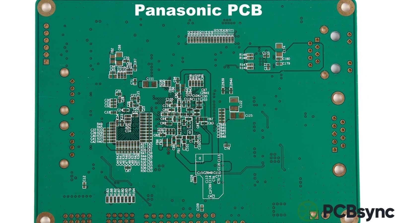
Megtron 6 is a high-performance PCB laminate developed by Panasonic, specifically engineered for high-speed digital and RF applications. The material uses a polyphenylene ether (PPE) resin system combined with low-Dk glass cloth, positioning it between standard FR-4 and expensive PTFE-based materials like Rogers.
What makes Megtron 6 stand out is its combination of PTFE-like electrical performance with FR-4-like processability. You get the low loss characteristics needed for 25 Gbps+ signals without the headaches of working with Teflon-based materials.
The Megtron 6 family includes several variants:
Megtron 6 (Standard) – R-5775 laminate with E-glass cloth
Megtron 6(N) – Low-Dk glass cloth version for even lower loss
Megtron 6(G) – Enhanced version for specific applications
Megtron 6(K) – PPO blend resin variant
Megtron 6 Halogen-Free – R-5375 for environmentally sensitive applications
MEGTRON PCB Calculator
PCBSync Engineering Tools
Materials
Impedance Calc
Layer Stackup
Design Tips
Cost Estimator
Select MEGTRON Grade
Material Properties
3.4
Dk (Dielectric Constant)
0.002
Df (Loss Tangent)
200°C
Tg (Glass Transition)
400°C
Td (Decomposition)
12
CTE Z-axis (ppm/°C)
Pass
CAF Resistance
MEGTRON Comparison Chart
Property
MEGTRON 4
MEGTRON 6
MEGTRON 7
MEGTRON 7N
Dk @10GHz
3.8
3.4
3.3
3.2
Df @10GHz
0.005
0.002
0.001
0.0008
Tg (°C)
175
200
200
200
Max Frequency
10 GHz
25 GHz
50 GHz
77+ GHz
Application
Standard
High-Speed
Premium
Ultra-Low Loss
Transmission Line Calculator
Calculated Impedance
50Ω
Signal Loss Calculator
Estimated Signal Loss
2.5dB
Stackup Configuration
Recommended 6-Layer Stackup
Layer
Type
Material
Thickness
Copper
L1
Signal (TOP)
–
–
1 oz
PP
Prepreg
MEGTRON 6
4 mil
–
L2
GND Plane
–
–
1 oz
Core
Core
MEGTRON 6
8 mil
–
L3
Signal
–
–
0.5 oz
PP
Prepreg
MEGTRON 6
40 mil
–
L4
Signal
–
–
0.5 oz
Core
Core
MEGTRON 6
8 mil
–
L5
PWR Plane
–
–
1 oz
PP
Prepreg
MEGTRON 6
4 mil
–
L6
Signal (BOT)
–
–
1 oz
MEGTRON PCB Design Guidelines
1
Choose the Right Grade
Use MEGTRON 4 for ≤10 GHz, MEGTRON 6 for 10-25 GHz, MEGTRON 7 for 25-50 GHz, and MEGTRON 7N for 77+ GHz (automotive radar, 5G mmWave). Higher grades cost more but offer lower loss.
2
Impedance Control
MEGTRON materials have tighter Dk tolerance (±0.05) than standard FR-4. Specify ±5% impedance tolerance for high-speed designs. Use controlled impedance stackups with consistent prepreg/core combinations.
3
Via Design for High-Speed
Use back-drilling to remove via stubs for signals >10 GHz. Keep via-to-via spacing ≥20 mil. Consider microvias (≤6 mil) for escape routing from fine-pitch BGAs.
4
Trace Width & Spacing
For 50Ω single-ended on MEGTRON 6 (4 mil dielectric): use ~4 mil trace width. For 100Ω differential: 3.5/4/3.5 mil (W/S/W). Avoid trace width below 3 mil for manufacturability.
5
Ground Plane Considerations
Place solid reference planes adjacent to all high-speed signal layers. Avoid splits/gaps under high-speed traces. Use ground via stitching (every 1/20 wavelength) around RF areas.
6
Surface Finish Selection
ENIG recommended for fine-pitch components. Consider ENEPIG for wire bonding. OSP is lowest cost but has limited shelf life. Immersion Silver offers good RF performance at moderate cost.
7
Hybrid Stackup Strategy
Combine MEGTRON with standard FR-4 for cost optimization. Use MEGTRON only for layers with high-speed signals; FR-4 for power/ground cores. Verify compatibility with your manufacturer.
8
Loss Budget Planning
Calculate total channel loss including: conductor loss (~0.5-1 dB/inch @10GHz), dielectric loss (material dependent), via transitions (~0.1-0.3 dB each), and connector losses. Keep total under channel budget.
PCB Cost Estimator
Cost Breakdown
Base PCB (FR-4 equivalent)
$45.00
MEGTRON Material Premium
$67.50
Layer Count Adder
$30.00
Fine Trace/Space
$15.00
Surface Finish (ENIG)
$12.00
Impedance Control
$25.00
Via Processing
$35.00
Estimated Total Cost (10 pcs)
$229.50
Unit price: $22.95/pc • Lead time: 10-15 days
Key Electrical Properties
The electrical characteristics of Megtron 6 directly determine how your high-speed signals behave. Here's what the datasheet numbers mean for your design.
Dielectric Constant and Loss
Property
Value @ 1 GHz
Value @ 10 GHz
Test Method
Dielectric Constant (Dk)
3.4 - 3.7
3.4 - 3.6
IPC TM-650 2.5.5.5
Dissipation Factor (Df)
0.002
0.004
IPC TM-650 2.5.5.5
Transmission Loss
~0.85 dB/inch @ 14 GHz
—
VNA measurement
The low Dk value (around 3.4-3.7 depending on construction) enables tighter impedance control and faster signal propagation compared to FR-4's typical 4.2-4.5 range. More importantly, the Df of 0.002 at 1 GHz means your signals lose less energy as heat—critical for long trace runs at high frequencies.
For context, standard FR-4 shows about 2 dB loss per inch at 14 GHz. Megtron 6 cuts that to roughly 0.85 dB per inch. On a 12-inch backplane trace, that's the difference between a readable eye diagram and a complete mess.
Dk Stability Across Frequency
One thing I appreciate about Megtron 6 is how flat its Dk stays across frequency. Here's what you can expect:
Frequency
Dk Value
Df Value
2 GHz
3.40
0.002
4 GHz
3.40
0.003
6 GHz
3.40
0.003
8 GHz
3.40
0.004
10 GHz
3.40
0.004
This stability simplifies your impedance calculations and reduces the risk of unexpected reflections at transition frequencies.
Thermal and Mechanical Specifications
High-speed signals generate heat, and your material needs to handle it. Megtron 6 delivers solid thermal performance that supports lead-free assembly and demanding operating environments.
Property
Value
Test Method
Glass Transition (Tg) - DSC
185°C
DSC
Glass Transition (Tg) - DMA
210°C
DMA
Thermal Decomposition (Td)
410°C (770°F)
TGA
Z-axis CTE (below Tg)
45 ppm/°C
IPC-TM-650 2.4.41
Time to Delamination (T288)
>120 min
IPC-TM-650 2.4.24.1
Moisture Absorption
0.14%
IPC-TM-650 2.6.2.1
Flammability
UL 94 V-0
IPC-TM-650 2.4.39
The 185°C Tg (DSC method) gives you plenty of margin for lead-free reflow soldering, which typically peaks around 260°C. The decomposition temperature of 410°C is exceptional—you won't be damaging this material during normal processing.
The Z-axis CTE of 45 ppm/°C is reasonable for a high-speed material, though you'll still want to pay attention to via reliability in thick boards with many thermal cycles.
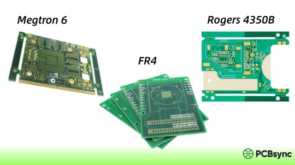
Choosing between these materials comes down to your performance requirements and budget. Here's an honest comparison based on real projects.
Parameter
FR-4 (Standard)
Megtron 6
Rogers 4350B
Dk @ 10 GHz
4.2 - 4.5
3.4 - 3.6
3.48
Df @ 10 GHz
0.020 - 0.025
0.004
0.0037
Tg (°C)
130 - 180
185
280
Loss @ 14 GHz (dB/inch)
~2.0
~0.85
~0.80
Relative Cost
1x
2-3x
4-6x
Processing
Standard
Standard FR-4
Modified
Best For
< 5 Gbps
10-56 Gbps
RF/Microwave
When to use FR-4: Signals under 5 Gbps, cost-sensitive designs, or non-critical routing layers in a hybrid stackup.
When to use Megtron 6: Digital signals from 10 Gbps to 56 Gbps, backplanes, networking equipment, and designs where you need good performance without PTFE processing complications.
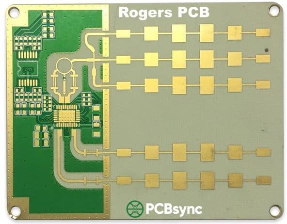
When to use Rogers 4350B: Pure RF applications, millimeter-wave designs, and cases where you need the absolute best electrical performance regardless of cost.
The biggest practical difference between Megtron 6 and Rogers? Processing. Megtron 6 uses the same lamination parameters as FR-4—same pressures, temperatures, and cure times. Rogers requires adjusted lamination cycles and discourages etchback. For production volumes, this processing simplicity saves real money.
Real-World Applications
Megtron 6 has found its way into most high-speed digital infrastructure. Here's where I've seen it deployed successfully.
Data Center and Server Infrastructure
Modern data centers run on 25G, 50G, and 100G Ethernet. Server backplanes and switch fabrics using Megtron 6 maintain signal integrity across 20+ inch trace lengths where FR-4 would fail. The material's consistency batch-to-batch also helps with production yield.
5G Telecommunications
Base station equipment, massive MIMO antenna arrays, and beamforming networks all benefit from Megtron 6's low loss at frequencies up to 6 GHz. The halogen-free variant (R-5375) meets environmental regulations for outdoor installations.
Network Equipment
Routers, switches, and optical transceivers operating at 40G, 100G, and 400G speeds rely on Megtron 6 for their high-speed serial links. IBM's z14 mainframes famously used Megtron 6 for their internal interconnects.
Test and Measurement
IC testers, network analyzers, and high-frequency measurement equipment need stable dielectric properties for accurate readings. Megtron 6's consistent Dk across frequency ranges makes it ideal for these precision applications.
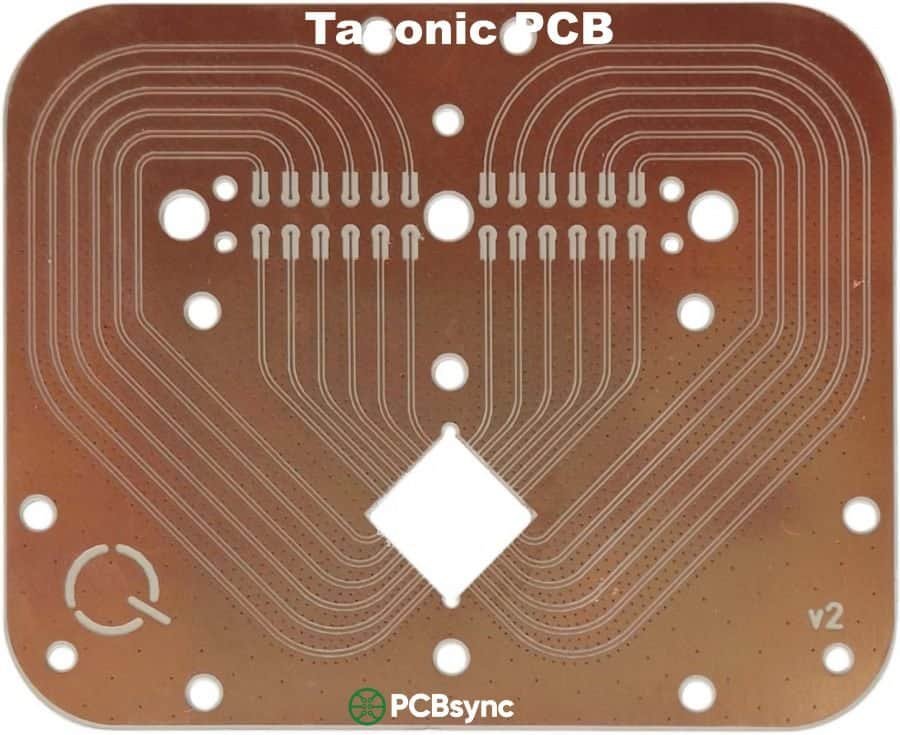
Automotive Radar
77 GHz automotive radar systems for ADAS use Megtron 6 in their digital processing sections, though the actual antenna elements often use even lower-loss materials like Rogers or Taconic laminates.
Stackup Design Guidelines
Getting your stackup right is critical with any high-speed material. Here are practical recommendations based on what works.
General Principles
Keep high-speed signals on inner stripline layers with solid reference planes immediately adjacent. The rule of thumb: route signals above 15 Gbps on stripline, and you can get away with microstrip for slower signals if needed.
For controlled impedance, target 4-5 mil dielectric spacing between signal and reference planes. Megtron 6 prepreg comes in multiple thicknesses and resin contents, so work with your fab house early to nail down available constructions.
Hybrid Stackup Strategy
Here's a cost-saving approach I use frequently: build the high-speed signal layers with Megtron 6 and use standard FR-4 for power planes and non-critical routing. Since Megtron 6 processes identically to FR-4, you can laminate them together in a single press cycle.
A typical 12-layer hybrid might look like:
Layer
Material
Purpose
L1
Megtron 6
High-speed microstrip
L2
FR-4
Ground reference
L3
FR-4
Power plane
L4
Megtron 6
High-speed stripline
L5
FR-4
Ground reference
L6
FR-4
Low-speed signals
L7
FR-4
Low-speed signals
L8
FR-4
Ground reference
L9
Megtron 6
High-speed stripline
L10
FR-4
Power plane
L11
FR-4
Ground reference
L12
Megtron 6
High-speed microstrip
Copper Foil Selection
Megtron 6 is available with three copper foil options:
H-VLP (Hyper Very Low Profile): Surface roughness ≤1.5 µm. Use this for signals above 10 GHz where skin effect losses dominate.
VLP (Very Low Profile): Good balance of loss and adhesion for most high-speed digital applications.
Standard: Higher adhesion but more loss. Use for power planes or non-critical layers.
For 25 Gbps+ designs, H-VLP copper is worth the premium. The smoother surface reduces conductor losses significantly at high frequencies.
Prepreg and Core Thickness Options
Megtron 6 comes in 18 different laminate thicknesses and multiple prepreg options. Common constructions include:
Glass Style
Resin Content
Typical Thickness
Dk @ 1 GHz
1035
70-75%
0.04 mm
3.28-3.35
1080
63%
0.06 mm
3.49
3313
54%
0.08 mm
3.71
2116
54-56%
0.10 mm
3.65-3.71
Higher resin content means lower Dk but also less mechanical rigidity. For HDI builds with microvias, the 1035 and 1078 glass styles with high resin content work well.
Impedance Control Tips
Consistent impedance is the whole point of using a premium material. Here's how to get it right.
Design for Manufacturing
Talk to your fab house before finalizing your stackup. They'll have specific Megtron 6 constructions in stock and can tell you what impedance tolerances are achievable. Most shops can hold ±10% on Megtron 6 with proper process control, and some can hit ±7%.
Glass Weave Effects
At high frequencies, the periodic structure of the glass weave can cause impedance variations. Megtron 6 addresses this with tightly woven, flat-glass styles and even resin distribution. For the most critical signals, route traces at angles to the glass weave pattern (not 0° or 90°) to average out the variations.
Simulation First
Before committing to fabrication, run your stackup through a 2.5D or 3D field solver. Tools like Ansys SIwave, Cadence Sigrity, or even free options like the Saturn PCB Toolkit can help you predict impedance and loss before spending money on prototypes.
Processing and Fabrication Notes
One reason Megtron 6 is popular with fabs: it behaves like FR-4 in the shop.
Lamination
Standard FR-4 press cycles work fine. No special temperature profiles, pressures, or cure times required. This is a major advantage over PTFE materials that need modified lamination parameters.
Drilling
Both mechanical drilling and laser drilling work well. For microvias, the material doesn't require plasma desmear like PTFE does—standard permanganate desmear is sufficient.
Plating
Through-hole plating proceeds normally. The Z-axis CTE of 45 ppm/°C provides good barrel crack resistance through thermal cycling, though it's not quite as robust as materials with lower CTE values.
Lead-Free Compatibility
Megtron 6 is fully compatible with lead-free assembly. The T288 time to delamination exceeds 120 minutes, giving you plenty of margin for multiple reflow cycles.
Cost Considerations
Let's talk money. Megtron 6 typically costs 2-3x the price of standard FR-4. Rogers 4350B runs 2x more than Megtron 6. But raw material cost isn't the whole picture.
Total Cost of Ownership
Factor in these items when comparing materials:
Processing costs: Megtron 6 uses standard FR-4 processes. PTFE materials require special handling.
Yield: Consistent material properties mean fewer rejected boards.
Rework: Better signal integrity reduces the need for signal boosters and redesigns.
Qualification: One material for both prototype and production simplifies qualification.
For high-volume production of networking equipment, the processing simplicity of Megtron 6 often makes it more economical than Rogers despite similar electrical performance.
When Premium Materials Don't Pay
Below 10 Gbps, you probably don't need Megtron 6. Enhanced FR-4 materials like Isola 370HR or FR408HR can handle moderate high-speed requirements at lower cost. Save the premium material for the traces that actually need it.
Storage and Handling
Megtron 6 requires controlled storage to maintain its properties.
Storage Conditions
Temperature: 20-25°C (68-77°F)
Humidity: 40-60% relative humidity
Shelf life: 3-6 months under proper conditions
Handling
Keep material in its moisture barrier bag until ready for use. If exposed to ambient conditions for extended periods, bake before lamination to drive out absorbed moisture.
Resources for Engineers
Here are the sources I reference regularly when working with Megtron 6:
Panasonic Official Datasheets – industrial.panasonic.com – Complete specifications and processing guidelines
Matrix Electronics Megtron 6 Page – matrixelectronics.com – North American distributor with technical support
IPC-4101 Specification – Industry standard that Megtron 6 meets (spec sheets 102 and 91)
Sierra Circuits Material Selection Guide – protoexpress.com – Good comparison between Rogers and Megtron materials
Frequently Asked Questions
Can Megtron 6 be mixed with FR-4 in the same board?
Yes, and this is actually a common cost-optimization strategy. Since Megtron 6 uses the same lamination parameters as FR-4, you can build hybrid stackups with Megtron 6 for high-speed layers and FR-4 for power planes or slow signals. The materials bond well together in a single lamination cycle.
What's the maximum frequency for Megtron 6?
Megtron 6 performs well up to about 20 GHz for digital applications. Beyond that, you'll start seeing increased losses, and materials like Megtron 7 or Rogers become better choices. For RF applications at millimeter-wave frequencies (77 GHz automotive radar, for example), Megtron 6 works for the digital backend but not for the antenna elements.
How does Megtron 6 compare to Megtron 4?
Megtron 4 is the older generation with higher loss (Df ~0.005 at 1 GHz vs. 0.002 for Megtron 6). For new designs above 10 Gbps, Megtron 6 is the better choice. Megtron 4 may still make sense for legacy designs or lower-speed applications where cost is the primary concern.
Is Megtron 6 suitable for flex or rigid-flex PCBs?
Megtron 6 is a rigid laminate, not suitable for flexible applications. For high-speed flex circuits, look at materials specifically designed for flex, like Rogers ULTRALAM or specialized polyimide-based materials.
What IPC specifications does Megtron 6 meet?
Megtron 6 conforms to IPC-4101 specification sheets /102 and /91, which define requirements for high-speed, low-loss laminates. It also meets UL 94 V-0 flammability requirements and RoHS compliance for lead-free applications.
Inquire: Call 0086-755-23203480, or reach out via the form below/your sales contact to discuss our design, manufacturing, and assembly capabilities.
Quote: Email your PCB files to Sales@pcbsync.com (Preferred for large files) or submit online. We will contact you promptly. Please ensure your email is correct.
Notes: For PCB fabrication, we require PCB design file in Gerber RS-274X format (most preferred), *.PCB/DDB (Protel, inform your program version) format or *.BRD (Eagle) format. For PCB assembly, we require PCB design file in above mentioned format, drilling file and BOM. Click to download BOM template To avoid file missing, please include all files into one folder and compress it into .zip or .rar format.


