Inquire: Call 0086-755-23203480, or reach out via the form below/your sales contact to discuss our design, manufacturing, and assembly capabilities.
Quote: Email your PCB files to Sales@pcbsync.com (Preferred for large files) or submit online. We will contact you promptly. Please ensure your email is correct.
Notes: For PCB fabrication, we require PCB design file in Gerber RS-274X format (most preferred), *.PCB/DDB (Protel, inform your program version) format or *.BRD (Eagle) format. For PCB assembly, we require PCB design file in above mentioned format, drilling file and BOM. Click to download BOM template To avoid file missing, please include all files into one folder and compress it into .zip or .rar format.
If you’ve ever worked on a pacemaker, patient monitor, or diagnostic imaging system, you know the stakes are different. A medical PCB isn’t just another circuit board—it’s the backbone of equipment that keeps people alive. After 15 years of designing boards for healthcare applications, I can tell you that getting this right requires understanding both the technical demands and the regulatory landscape that governs our industry.
This guide covers everything engineers and procurement teams need to know about medical PCB design, manufacturing, and assembly. Whether you’re developing a Class II glucose monitor or a Class III implantable defibrillator, the principles here will help you build boards that perform reliably when it matters most.
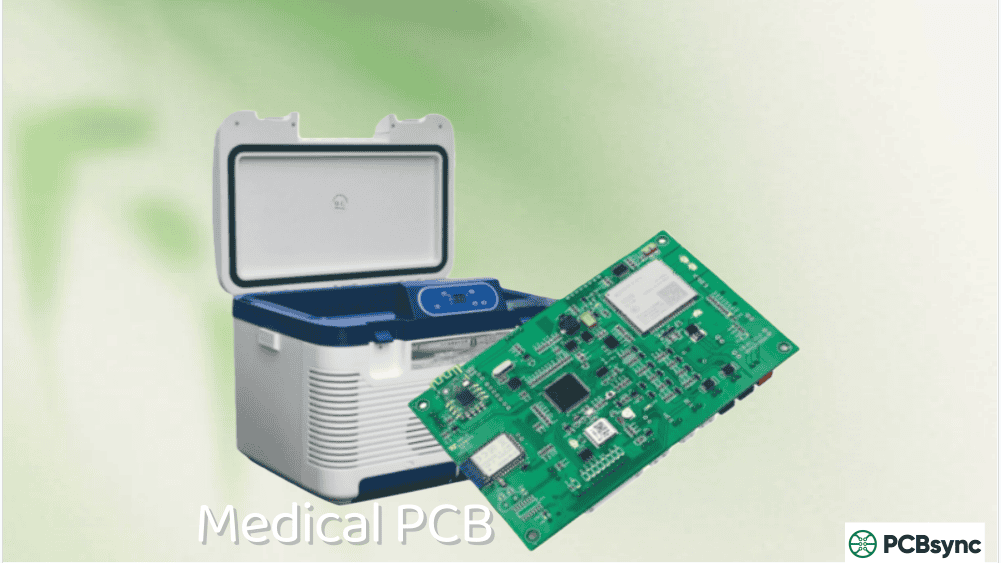
A medical PCB is a printed circuit board specifically designed and manufactured to meet the stringent requirements of healthcare applications. Unlike consumer electronics where occasional failures might be inconvenient, medical PCB failures can directly impact patient safety and clinical outcomes.
Medical PCBs power everything from simple blood pressure monitors to complex MRI systems. They must deliver consistent performance across demanding conditions including sterilization processes, temperature extremes, and continuous operation. The manufacturing tolerances are tighter, the documentation requirements are extensive, and the testing protocols are far more rigorous than standard electronics.
What sets medical-grade boards apart:
Zero-defect tolerance for life-sustaining equipment
Full traceability from raw materials to finished assembly
Extended lifecycle support often exceeding 10-15 years
Compliance with IPC Class 3 high-reliability specifications
Biocompatibility requirements for patient-contact devices
Types of Medical PCBs
The choice of PCB type depends on your device’s mechanical constraints, electrical requirements, and operating environment. Here’s what works best for different medical applications:
PCB Type
Best Applications
Key Advantages
Typical Layer Count
Rigid PCB
MRI machines, CT scanners, X-ray equipment
Structural stability, cost-effective for large boards
Rigid boards remain the workhorse of medical imaging and monitoring equipment. When I designed the control board for a CT scanner last year, we used a 16-layer rigid stackup to handle the complex signal routing and power distribution requirements. The mechanical stability of FR-4 based rigid boards makes them ideal for equipment that stays in fixed installations.
Flexible Medical PCBs
Flex circuits have transformed wearable medical devices. The polyimide substrate can withstand thousands of flex cycles without cracking—critical for devices worn on the body or threaded through surgical cavities. We’re seeing flex PCBs in everything from continuous glucose monitors to catheter-based diagnostic tools.
HDI Medical PCBs
High-Density Interconnect technology has become essential for implantables and portable diagnostics. With laser-drilled microvias as small as 0.1mm, HDI allows us to pack sophisticated functionality into spaces that seemed impossible a decade ago. A modern cochlear implant processor contains more computing power than early smartphones, all on a board smaller than your thumbnail.
Medical PCB Design Considerations
Getting the design right from the start prevents costly revisions and regulatory delays. These are the factors that separate successful medical PCB projects from troubled ones.
Material Selection for Medical Applications
Your substrate choice affects everything from signal integrity to sterilization compatibility:
For devices requiring autoclave sterilization at 121-134°C, standard FR-4 won’t cut it. You need high-Tg materials that maintain structural integrity through repeated sterilization cycles.
EMI and EMC Requirements
Medical devices must coexist in electrically noisy hospital environments without causing or experiencing interference. The IEC 60601-1-2 standard sets strict emissions and immunity limits. Design practices that help:
Ground plane strategies: Use solid ground planes with strategic splits only where necessary. Avoid slotting under high-speed traces.
Shield placement: Critical analog circuits need localized shielding, especially ADCs in monitoring equipment.
Filtering: Place ferrite beads and common-mode chokes at cable entry points.
Trace routing: Keep high-speed digital traces short and away from sensitive analog sections.
Thermal Management
Many medical PCBs operate continuously for years. Poor thermal design leads to premature component failures and reduced device lifespan. Effective approaches include:
Increasing copper weight to 2-3 oz on power layers for better heat spreading
Using thermal vias under hot components to conduct heat to inner layers
Specifying metal-core substrates for high-power therapeutic devices
Leaving adequate clearance around heat-generating components
Biocompatibility for Patient-Contact Devices
When a PCB will contact body fluids or tissue—either directly or through device housing migration—biocompatibility testing per ISO 10993 becomes mandatory. This affects:
Solder mask selection: Some mask formulations leach compounds that fail cytotoxicity testing
Surface finish: ENIG (Electroless Nickel Immersion Gold) is often preferred for its inertness
Conformal coating: Parylene coatings provide excellent biocompatible barriers
Lead-free requirements: All medical PCBs should comply with RoHS directive
Medical PCB Manufacturing Process
Manufacturing medical PCBs requires validated processes, documented procedures, and extensive quality controls at every step.
The key difference in medical PCB manufacturing is documentation. Every material lot, process parameter, and inspection result must be traceable. When the FDA asks about a specific device, you need to reconstruct exactly how its PCB was made.
Assembly adds another layer of complexity. Most medical PCBs combine SMT (Surface Mount Technology) and through-hole components, requiring careful process sequencing.
SMT Assembly for Medical Devices
Surface mount dominates modern medical electronics for good reasons—smaller footprints, better high-frequency performance, and automated placement accuracy down to 0.01mm. The typical SMT flow:
Solder paste application: Stencil printing with paste inspection (SPI)
Component placement: Pick-and-place with vision alignment
Reflow soldering: Controlled profile with nitrogen atmosphere for oxidation-sensitive components
Post-reflow inspection: AOI followed by X-ray for hidden joints under BGAs
High-current connectors that need mechanical strength
Large electrolytic capacitors
Components requiring field replacement
Selective wave soldering or hand soldering with IPC J-STD-001 certified operators maintains quality while preserving temperature-sensitive SMT components.
Cleanroom Requirements
Medical PCB assembly typically occurs in ISO Class 7 or Class 8 cleanrooms. Higher-risk implantable devices may require ISO Class 6 environments. Cleanroom practices include:
Controlled temperature and humidity
HEPA-filtered air circulation
ESD-protected workstations
Gowning procedures for personnel
Restricted material handling protocols
Regulatory Standards and Certifications
Navigating medical device regulations requires understanding multiple overlapping standards from different governing bodies.
Key Standards Summary
Standard
Issuing Body
Scope
ISO 13485:2016
ISO
Quality management system for medical devices
IPC-6012 Class 3
IPC
Performance specs for high-reliability rigid PCBs
IPC-A-610 Class 3
IPC
Acceptability criteria for electronic assemblies
IEC 60601-1
IEC
Safety requirements for medical electrical equipment
21 CFR Part 820
FDA
Quality system regulation for US market
ISO 10993
ISO
Biocompatibility evaluation
IPC-6012EM
IPC
Medical applications addendum for implantables
IPC Class 3 Requirements
Class 3 represents the highest reliability tier. For medical PCBs, this means:
What is the difference between medical PCB and regular PCB?
Medical PCBs must meet IPC Class 3 high-reliability specifications with tighter tolerances, more rigorous testing, and complete documentation traceability. They require ISO 13485 certified manufacturing processes and often need biocompatibility testing. Regular consumer PCBs typically meet Class 2 specifications with less stringent quality requirements and minimal documentation.
How long does it take to manufacture medical PCBs?
Standard medical PCB manufacturing takes 3-4 weeks for prototypes and 6-8 weeks for production quantities. Complex HDI designs or boards requiring specialized materials may take longer. Quick-turn services can deliver prototypes in 5-10 days, though at premium pricing. Factor in additional time for first article inspection approval and any required documentation packages.
What certifications should a medical PCB manufacturer have?
At minimum, look for ISO 13485:2016 certification (quality management for medical devices), ISO 9001:2015 (general quality management), and IPC Class 3 manufacturing capability. For US market devices, FDA establishment registration is required. Additional valuable certifications include UL recognition, ITAR registration for defense-related medical devices, and AS9100 if serving aerospace medical applications.
Can standard FR-4 material be used for medical PCBs?
Standard FR-4 works for many medical applications including patient monitors and diagnostic equipment that don’t undergo sterilization. However, devices requiring autoclave sterilization need high-Tg FR-4 (170°C+) or polyimide substrates. Implantable devices often require specialized materials like ceramic or PTFE that provide better biocompatibility and hermeticity. Always verify material compatibility with your device’s sterilization and operating requirements.
What testing is required for medical PCB assemblies?
Medical PCBA testing typically includes In-Circuit Testing (ICT) for component verification, Functional Circuit Testing (FCT) for operational validation, Automated Optical Inspection (AOI) for solder joint quality, and X-ray inspection for hidden connections under BGAs and QFNs. Life-sustaining devices require additional Highly Accelerated Life Testing (HALT) and environmental stress screening. All test results must be documented and retained per your quality system requirements.
Final Thoughts
Building medical PCBs requires a different mindset than consumer electronics. Every design decision, manufacturing process, and quality check carries the weight of patient safety. The regulations exist because failures in medical devices have real consequences.
The good news is that following established standards and working with experienced partners dramatically reduces risk. Start with a solid understanding of your device classification and applicable standards. Choose materials and processes appropriate for your application. Partner with manufacturers who understand medical device requirements and can demonstrate their capabilities through certifications and track record.
The medical device industry continues evolving toward smaller, smarter, and more connected products. Staying current with HDI technology, flex circuit capabilities, and emerging standards positions you to design the next generation of life-improving medical electronics.
Inquire: Call 0086-755-23203480, or reach out via the form below/your sales contact to discuss our design, manufacturing, and assembly capabilities.
Quote: Email your PCB files to Sales@pcbsync.com (Preferred for large files) or submit online. We will contact you promptly. Please ensure your email is correct.
Notes: For PCB fabrication, we require PCB design file in Gerber RS-274X format (most preferred), *.PCB/DDB (Protel, inform your program version) format or *.BRD (Eagle) format. For PCB assembly, we require PCB design file in above mentioned format, drilling file and BOM. Click to download BOM template To avoid file missing, please include all files into one folder and compress it into .zip or .rar format.


