Inquire: Call 0086-755-23203480, or reach out via the form below/your sales contact to discuss our design, manufacturing, and assembly capabilities.
Quote: Email your PCB files to Sales@pcbsync.com (Preferred for large files) or submit online. We will contact you promptly. Please ensure your email is correct.
Notes: For PCB fabrication, we require PCB design file in Gerber RS-274X format (most preferred), *.PCB/DDB (Protel, inform your program version) format or *.BRD (Eagle) format. For PCB assembly, we require PCB design file in above mentioned format, drilling file and BOM. Click to download BOM template To avoid file missing, please include all files into one folder and compress it into .zip or .rar format.
Intel MAX 10 FPGA: Features, Part Numbers & Development Guide
When I first encountered the MAX10 FPGA back in 2014, it fundamentally changed how I approached low-cost embedded designs. Here was a device that finally bridged the gap between traditional CPLDs and full-featured FPGAs—offering instant-on capability, integrated ADCs, and enough logic resources to run a Nios II processor, all without external configuration memory.
The Altera MAX10 family (now under Intel’s umbrella as Intel FPGA MAX10) represents a unique position in the programmable logic landscape. Whether you’re searching for part numbers like 10M08SAE144C8G or 10M02SCE144I7G, or evaluating the Altera BeMicroMAX10 development kit, this comprehensive guide covers everything you need to design with these versatile devices.
The MAX10 FPGA breaks the traditional FPGA mold. Unlike conventional SRAM-based FPGAs that require external configuration memory and take hundreds of milliseconds to boot, MAX 10 devices feature integrated flash memory that enables configuration in less than 10 milliseconds. This “instant-on” capability was previously only available in CPLDs.
Key Architectural Features:
Feature
Specification
Process Technology
55nm Flash
Configuration Time
< 10 ms
Sleep Mode Wake-up
< 1 ms
Logic Elements
2,000 to 50,000
On-chip User Flash
Up to 736 Kbits
Embedded Memory
Up to 1,638 Kbits
DSP Blocks
Up to 144 (18×18 multipliers)
PLLs
Up to 4
ADC Blocks
Up to 2 (12-bit, 1 MSPS)
Is MAX 10 a CPLD or FPGA?
This question comes up frequently, and the answer reveals Intel’s clever positioning. While marketed alongside the MAX CPLD family, the MAX10 CPLD designation is technically a misnomer. The architecture is fundamentally FPGA-based, using Look-Up Tables (LUTs) organized in Logic Array Blocks (LABs), not the product-term macrocells found in true CPLDs.
However, MAX 10 delivers CPLD-like benefits:
Non-volatile configuration (no external boot ROM needed)
Instant-on operation
Single-chip solution
Predictable power-on behavior
The difference is that MAX 10’s SRAM-based logic fabric loads from internal flash at power-up, giving you FPGA performance with CPLD convenience.
Intel MAX 10 Device Family Overview
Complete Device Lineup
The Altera MAX10 FPGA family spans from tiny 2K LE devices to substantial 50K LE parts:
Device
Logic Elements
M9K Blocks
User Flash (Kbits)
PLLs
ADC Blocks
Max I/Os
10M02
2,000
7
96
2
0*
130
10M04
4,000
21
160
2
1
246
10M08
8,000
42
288
2
1-2
250
10M16
16,000
66
528
4
2
320
10M25
25,000
89
675
4
2
360
10M40
40,000
126
736
4
2
360
10M50
50,000
182
736
4
2
360
*Note: 10M02 devices do not include ADC blocks.
Single-Supply vs Dual-Supply Variants
Intel offers MAX 10 in two power supply configurations:
Single-Supply Devices (Compact):
Simplified power design with single 3.0V or 3.3V supply
Internal voltage regulator generates 1.2V core voltage
Ideal for space-constrained applications
Device codes include “S” (e.g., 10M08SAE144C8G)
Dual-Supply Devices (Analog):
Separate 1.2V core and 2.5V/3.3V I/O supplies
Better ADC performance with cleaner analog references
Recommended for precision analog applications
Device codes include “D” (e.g., 10M08DAF484C8G)
Understanding MAX 10 Part Numbers
Decoding the Ordering Code
Part numbers like 10M08SAE144C8G or 10M02SCE144I7G follow a specific structure. Let me break down 10M08SAE144C8G as an example:
Position
Code
Meaning
10M
—
MAX 10 family
08
—
8,000 Logic Elements
S
—
Single-supply device
A
—
Analog features (ADC)
E144
—
144-pin EQFP package
C
—
Commercial temperature (0°C to 85°C)
8
—
Speed grade 8
G
—
Lead-free (RoHS compliant)
Feature Options Explained
Code
Feature Description
SA
Single-supply with ADC
SC
Single-supply, Compact (no ADC)
DA
Dual-supply with ADC
DC
Dual-supply, Compact (no ADC)
SL
Single-supply with SEU mitigation
DD
Dual-supply with dual configuration
Common Part Numbers Reference
Here are frequently specified Altera 10M08 and Altera 10M02SCU169C8G variants:
Part Number
Description
I/Os
ADC
Package
10M02SCE144I7G
2K LE, Industrial, No ADC
101
No
144-EQFP
10M02SCU169C8G
2K LE, Commercial, No ADC
130
No
169-UBGA
10M08SAE144C8G
8K LE, Commercial, ADC
101
Yes
144-EQFP
10M08SAU169C8G
8K LE, Commercial, ADC
130
Yes
169-UBGA
10M08SAF484C8G
8K LE, Commercial, ADC
250
Yes
484-FBGA
10M16SAU169C8G
16K LE, Commercial, ADC
130
Yes
169-UBGA
10M50DAF484C8G
50K LE, Commercial, ADC
360
Yes
484-FBGA
Temperature and Speed Grade Options
Temperature Grades:
C: Commercial (0°C to 85°C)
I: Industrial (-40°C to 100°C)
A: Automotive (-40°C to 125°C)
Speed Grades:
6: Fastest (limited availability)
7: Fast
8: Standard
Analog-to-Digital Converter (ADC) Integration
ADC Architecture Overview
One of the most compelling features of the Intel FPGA MAX10 is its integrated 12-bit ADC. Having designed numerous mixed-signal systems, I can confirm that eliminating external ADC chips saves significant board space, reduces BOM cost, and simplifies routing.
ADC Specifications:
Parameter
Specification
Resolution
12 bits
Sample Rate
Up to 1 MSPS (cumulative)
Input Channels
Up to 18 (device dependent)
Input Voltage Range
0 to VREF
Reference Options
Internal 2.5V or External
Temperature Sensor
Integrated on-die TSD
INL
±2 LSB typical
DNL
±1 LSB typical
ADC Channel Configuration
MAX 10 devices support multiple ADC input types:
Dedicated ADC Pins:
Optimized for analog performance
Best SNR and THD specifications
Available on specific I/O banks
Dual-Function Pins:
Can serve as either GPIO or analog input
Slightly reduced analog performance
Flexible pin assignment
Implementing ADC in Quartus
The MAX10 Quartus development flow includes the Modular ADC Core IP for easy ADC integration:
Platform Designer (Qsys) → Modular ADC Core IP
↓
Configure: Channels, Sample Rate, Reference
↓
Generate HDL → Connect to User Logic
↓
Access via Avalon-MM Interface
The ADC IP core supports four configuration variants:
Standard Sequencer with Avalon-MM Sample Storage
Standard Sequencer with Threshold Violation Detection
Standard Sequencer with External Sample Storage
ADC Control Core Only (for custom implementations)
Development with Quartus Prime
Quartus Prime Software Support
The MAX10 Quartus toolchain is fully supported in Quartus Prime Lite Edition (free), making MAX 10 an excellent choice for cost-sensitive projects and education.
Software Requirements:
Quartus Version
MAX 10 Support
Notes
Quartus Prime 23.1+
Full
Current recommended
Quartus Prime 18.1-22.x
Full
Stable releases
Quartus Prime 15.0-17.x
Full
Legacy support
Quartus II 14.1
Initial
First MAX 10 release
Creating Your First MAX 10 Project
Launch Quartus Prime Lite (free download from Intel)
Create New Project → Select MAX 10 device family
Choose specific device (e.g., 10M08SAE144C8G)
Import pin assignments from development kit QSF file
MAX 10 devices with 8K+ LEs can comfortably host a Nios II/e processor:
Typical Nios II System Resources:
Component
Approximate LEs
Nios II/e (economy)
600-700
Nios II/f (fast)
1,400-1,800
JTAG Debug Module
200-400
Timer
100-200
UART
100-200
GPIO
50-100
On-chip RAM
Varies
A basic Nios II system fits comfortably in 10M08 devices, leaving room for custom peripherals.
Useful Resources and Downloads
Official Intel/Altera Resources
Resource
URL
Description
MAX 10 FPGA Overview
intel.com/max10
Product landing page
Device Handbook
intel.com/programmable
Complete technical reference
Quartus Prime Lite
intel.com/quartus
Free development software
Pin-out Files
intel.com/support
Package pin assignments
Design Examples
github.com/intel
Reference designs
Technical Documentation
Document
Content
MAX 10 Device Overview
Architecture, features, ordering
MAX 10 Device Datasheet
Electrical specifications, timing
MAX 10 ADC User Guide
ADC implementation details
MAX 10 User Flash Memory Guide
UFM programming
MAX 10 Configuration Guide
Boot modes, dual image
AN 905
Board Design Guidelines
Development Kit Resources
Kit
Support Page
MAX 10 FPGA Dev Kit
altera.com/devkits
BeMicro MAX 10
arrow.com/bemicro
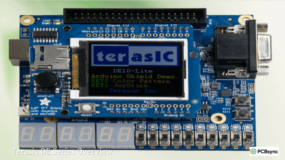
DE10-Lite
terasic.com/de10-lite
Community Resources
Intel FPGA Forum (community.intel.com)
FPGAcademy.org (educational materials)
OpenCores.org (free IP cores)
Reddit r/FPGA
Frequently Asked Questions (FAQs)
What is the difference between MAX 10 and MAX V devices?
MAX V devices are true CPLDs with macrocell-based architecture, offering up to 2,210 logic elements. MAX10 FPGA devices use LUT-based FPGA architecture with up to 50,000 logic elements, integrated ADCs, DSP blocks, and embedded memory. MAX 10 replaces MAX V for applications requiring more than basic glue logic. While both are non-volatile and instant-on, MAX 10 provides significantly more resources and features.
Can I use MAX 10 FPGA without external configuration memory?
Yes, this is one of MAX 10’s primary advantages. The integrated flash memory stores your configuration internally, eliminating the need for external SPI flash, EPROM, or configuration controllers. The device self-configures in less than 10ms at power-up. You can also store user data in the User Flash Memory (UFM) block—up to 736 Kbits depending on device density.
Which Quartus version should I use for MAX 10 development?
For new designs, use Quartus Prime Lite Edition (free) version 23.1 or later. All MAX10 Quartus development is fully supported in the free Lite edition—you don’t need Standard or Pro editions. Earlier versions back to Quartus Prime 15.0 also support MAX 10, but newer versions include bug fixes, improved timing analysis, and better IP support. The free ModelSim-Intel starter edition is included for simulation.
How does the 10M08SAE144C8G compare to similar parts?
The 10M08SAE144C8G is one of the most popular MAX 10 variants for prototyping and production. It provides 8,000 LEs, integrated ADC, 101 I/Os in a 144-pin EQFP package at commercial temperature (0-85°C) with speed grade 8. For industrial temperature (-40°C to 100°C), use 10M08SAE144I7G. For more I/Os, consider 10M08SAU169C8G (169-UBGA, 130 I/Os) or 10M08SAF484C8G (484-FBGA, 250 I/Os). The 10M02SCE144I7G offers a lower-cost option with 2,000 LEs but no ADC.
Is MAX 10 suitable for automotive applications?
Yes, Intel offers automotive-grade MAX 10 devices (designated with “A” temperature grade: -40°C to 125°C) that are AEC-Q100 qualified. These devices are used in automotive applications including infotainment, ADAS preprocessing, instrument clusters, and body electronics. The non-volatile configuration is particularly valuable in automotive environments where instant-on behavior and reliable cold-start operation are critical requirements.
Migration and Device Selection Strategy
Vertical Migration Support
One advantage of the MAX 10 family is vertical migration capability. You can design with a smaller device during prototyping and migrate to larger densities for production—or vice versa—without PCB changes.
Migration Paths by Package:
Package
Compatible Devices
E144
10M02, 10M04, 10M08
U169
10M02, 10M04, 10M08, 10M16
U324
10M08, 10M16, 10M25
F256
10M04, 10M08, 10M16
F484
10M08, 10M16, 10M25, 10M40, 10M50
F672
10M25, 10M40, 10M50
When planning for migration, restrict your I/O usage to the lowest common denominator in your migration path. The Quartus Prime Pin Planner helps identify migration-compatible pin assignments.
Selecting the Right Device
Consider these factors when choosing a MAX 10 device:
Logic Requirements:
Basic glue logic: 10M02 (2K LEs)
Simple state machines: 10M04-10M08 (4K-8K LEs)
Nios II systems: 10M08-10M16 (8K-16K LEs)
Complex designs: 10M25-10M50 (25K-50K LEs)
I/O Requirements:
Low pin count: V36, V81 (WLCSP)
Moderate: E144, M153, U169
High pin count: F484, F672
Analog Requirements:
No ADC needed: Select “SC” or “DC” variants (lower cost)
ADC required: Select “SA” or “DA” variants
Precision ADC: Use dual-supply “DA” variants
Environmental:
Lab/Consumer: Commercial (C) grade
Industrial: Industrial (I) grade
Automotive: Automotive (A) grade
Power Consumption and Thermal Management
Power Estimation
MAX 10 power consumption depends on design complexity, clock frequencies, and I/O activity. The Quartus Prime Power Analyzer provides accurate estimates after place-and-route.
Typical Power Consumption:
Device
Static Power
Dynamic Power (Typical)
10M02
15-25 mW
50-150 mW
10M08
25-40 mW
100-300 mW
10M16
35-55 mW
150-400 mW
10M50
60-100 mW
300-800 mW
Values vary based on temperature, voltage, and design activity.
Sleep Mode and Power Management
MAX 10 supports power management features:
Sleep Mode:
Core logic powered down
Configuration retained in flash
Wake-up in < 1 ms
Standby current as low as 100 µA
Power-On Reset (POR):
Internal POR circuit monitors supply voltages
Configurable POR threshold
Clean startup sequence
Thermal Considerations
For designs pushing MAX 10 limits:
Calculate junction temperature: Tj = Ta + (Pd × θJA)
Add thermal relief: Use ground planes and thermal vias
Consider airflow: Moving air significantly improves θJA
Comparison with Competing Devices
MAX 10 vs Lattice MachXO3
Feature
Intel MAX 10
Lattice MachXO3
Max Logic
50K LEs
6.9K LUTs
Non-volatile
Yes
Yes
ADC
Integrated 12-bit
No
DSP Blocks
Up to 144
Limited
DDR3 Support
Yes
No
Price Range
$$
$
MAX 10 offers significantly more resources but at higher cost. MachXO3 suits simpler applications.
MAX 10 vs Xilinx Spartan-7
Feature
Intel MAX 10
Xilinx Spartan-7
Non-volatile
Yes (internal)
No (external flash)
Instant-on
Yes (< 10 ms)
No (100+ ms)
ADC
Integrated
XADC (limited)
Logic Range
2K-50K
6K-100K
Memory
M9K blocks
Block RAM
Spartan-7 offers more logic but requires external configuration memory. MAX 10’s instant-on is a key differentiator.
When to Choose MAX 10
Choose MAX 10 when you need:
Instant-on operation without external boot memory
Integrated ADC for mixed-signal applications
Single-chip solution for board space savings
Cost-effective design with free development tools
Reliable operation in harsh environments
Quick power-cycling with immediate functionality
Consider alternatives when you need:
Logic density exceeding 50K LEs
High-speed transceivers
Hard processor systems (ARM cores)
Maximum clock frequencies (> 450 MHz)
Conclusion
The Intel MAX 10 FPGA family occupies a unique position in programmable logic—delivering FPGA flexibility with CPLD convenience. Whether you’re selecting an Altera MAX10 device for a new design, decoding part numbers like 10M08SAE144C8G or 10M02SCE144I7G, or evaluating development platforms like the Altera BeMicroMAX10, MAX 10 provides a compelling solution for cost-sensitive, space-constrained applications requiring instant-on operation.
The integrated ADC, dual-boot capability, and free MAX10 Quartus toolchain make these devices particularly attractive for industrial IoT, system management, and embedded control applications. With densities from 2K to 50K logic elements, there’s a MAX 10 device suited to virtually any low-to-mid complexity design requirement.
From my experience, the sweet spot for most applications lies in the 10M08 to 10M16 range—enough resources for a Nios II processor with custom peripherals, integrated ADC for sensor interfacing, and sufficient I/Os for typical embedded applications, all in packages that don’t require advanced PCB technology.
Suggested Meta Descriptions:
Option 1 (158 characters): “Complete Intel MAX 10 FPGA guide: features, part numbers (10M08SAE144C8G, 10M02SCE144I7G), ADC integration, Quartus development, and BeMicroMAX10 board review.”
Option 2 (155 characters): “Altera MAX10 FPGA development guide covering part number decoding, ADC features, Quartus Prime setup, and comparison of DE10-Lite and BeMicroMAX10 boards.”
Option 3 (152 characters): “Intel FPGA MAX10 complete reference: non-volatile FPGA features, ordering codes for 10M08 and 10M02 series, PCB design tips, and development resources.”
Inquire: Call 0086-755-23203480, or reach out via the form below/your sales contact to discuss our design, manufacturing, and assembly capabilities.
Quote: Email your PCB files to Sales@pcbsync.com (Preferred for large files) or submit online. We will contact you promptly. Please ensure your email is correct.
Notes: For PCB fabrication, we require PCB design file in Gerber RS-274X format (most preferred), *.PCB/DDB (Protel, inform your program version) format or *.BRD (Eagle) format. For PCB assembly, we require PCB design file in above mentioned format, drilling file and BOM. Click to download BOM template To avoid file missing, please include all files into one folder and compress it into .zip or .rar format.


