Inquire: Call 0086-755-23203480, or reach out via the form below/your sales contact to discuss our design, manufacturing, and assembly capabilities.
Quote: Email your PCB files to Sales@pcbsync.com (Preferred for large files) or submit online. We will contact you promptly. Please ensure your email is correct.
Notes: For PCB fabrication, we require PCB design file in Gerber RS-274X format (most preferred), *.PCB/DDB (Protel, inform your program version) format or *.BRD (Eagle) format. For PCB assembly, we require PCB design file in above mentioned format, drilling file and BOM. Click to download BOM template To avoid file missing, please include all files into one folder and compress it into .zip or .rar format.
When I first started working with printed circuit boards fifteen years ago, we rarely saw true mixed technology assemblies. Today, they’re everywhere. From automotive control units to industrial automation systems, mixed PCB assembly has become the standard approach for building robust, high-performance electronics. If you’re designing products that need both miniaturized components and mechanical durability, understanding mixed assembly isn’t optional—it’s essential.
Mixed PCB assembly combines Surface Mount Technology (SMT) with Through-Hole Technology (THT) on a single board. This hybrid approach lets you leverage SMT’s space efficiency for integrated circuits and small passives while using through-hole components for connectors, power devices, and anything requiring serious mechanical strength. The challenge lies in getting both technologies to work together seamlessly during manufacturing.
Understanding the Fundamentals of Mixed Technology PCB Assembly
What Makes Mixed Assembly Different
Mixed technology assembly isn’t simply placing two types of components on the same board. The manufacturing process requires careful sequencing because SMT and THT use fundamentally different soldering methods. SMT components attach to surface pads using reflow soldering, typically around 240-260°C. Through-hole parts need their leads inserted into drilled holes and soldered using wave soldering, selective soldering, or hand soldering techniques.
The real complexity emerges when you consider thermal exposure. Your SMT components will experience heat multiple times—first during reflow, then potentially again during THT soldering. This repeated thermal stress can damage sensitive components if you don’t plan the assembly sequence properly.
When to Use Mixed Assembly Technology
I’ve found mixed assembly makes sense in several scenarios:
High-power applications: Power supplies need large through-hole capacitors and transformers for their power-handling capacity, but the control circuitry benefits from compact SMT components. You can’t build a reliable 500W power supply using only SMT parts—the mechanical stress and heat dissipation requirements demand through-hole technology for key components.
Mechanical durability requirements: Automotive and industrial applications face vibration, shock, and temperature cycling. Through-hole connectors provide the mechanical strength to withstand these stresses, while SMT handles the signal processing and logic circuits. An engine control unit subjected to constant vibration needs through-hole connectors at its interface points.
Component availability constraints: Sometimes you simply can’t get a specific component in SMT packaging. Certain high-current relays, specialized connectors, and legacy components only exist in through-hole form. Mixed assembly lets you incorporate these parts without compromising your overall design density.
Key Differences Between SMT and Through-Hole Components
Understanding the characteristics of each technology helps you make better component placement decisions.
Characteristic
SMT Components
Through-Hole Components
Mounting Method
Surface pads on PCB
Leads through drilled holes
Mechanical Strength
Lower, relies on solder fillet
Higher, leads go through board
Component Size
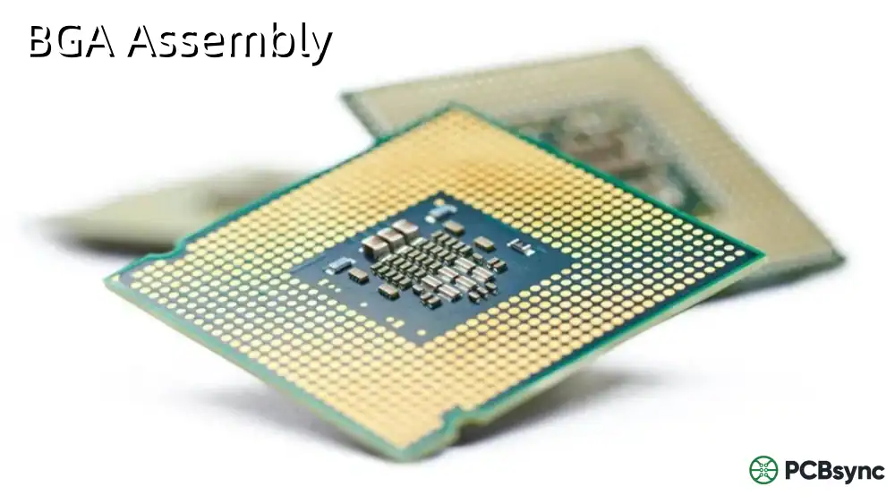
Typically smaller (0201-BGA)
Larger footprint required
Assembly Speed
Fast automated placement
Slower, may need manual work
Rework Difficulty
Moderate to difficult
Easier to replace
Thermal Management
Limited thermal mass
Better heat dissipation path
Cost per Placement
Lower at volume
Higher per component
Signal Integrity
Shorter leads, less inductance
Longer leads can add inductance
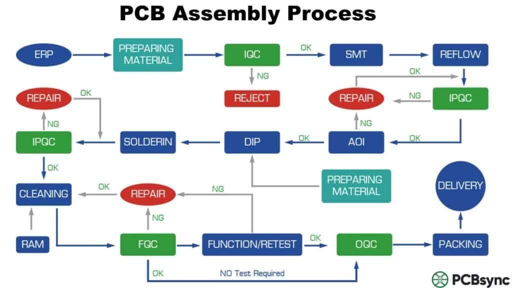
The Mixed PCB Assembly Process Flow
Getting mixed assembly right requires understanding the complete manufacturing sequence. Here’s how professional assembly houses handle these boards:
Step 1: Solder Paste Application
The process starts with solder paste printing for SMT components. A stainless steel stencil aligns with the bare PCB, and a squeegee forces solder paste through apertures onto the SMT pads. The paste contains tiny solder spheres suspended in flux. Paste thickness typically ranges from 0.004 to 0.006 inches, depending on component types.
For mixed assemblies, you need to mask or block through-holes during paste application. Otherwise, solder paste fills the holes, preventing proper through-hole lead insertion later. Some manufacturers use plugging paste or tape, while others design stencils that simply don’t cover the through-hole areas.
Step 2: SMT Component Placement
Pick-and-place machines position surface mount components onto the solder paste. Modern equipment achieves placement speeds of 30,000 components per hour with accuracy within ±0.001 inch. The machines use vacuum nozzles to pick components from reels, trays, or tubes, rotating them to the correct orientation before placement.
Component orientation matters significantly in mixed assemblies. Position SMT parts considering the upcoming through-hole soldering process. Keep heat-sensitive SMT components away from areas that will see high temperatures during wave or selective soldering.
Step 3: Reflow Soldering
The board enters a reflow oven where controlled heating melts the solder paste, creating permanent electrical and mechanical connections. A typical lead-free reflow profile includes:
Preheat zone: 150-180°C to activate flux
Soak zone: 180-200°C to stabilize temperature
Reflow zone: 240-260°C peak temperature
Cooling zone: Controlled cooldown to below 200°C
The entire process takes 4-8 minutes depending on board thickness and thermal mass.
Step 4: Post-Reflow Inspection
Automated Optical Inspection (AOI) systems check SMT placement quality before proceeding to through-hole assembly. Catching defects now saves time and cost compared to finding them after THT soldering. Common issues include tombstoning, bridging, and component misalignment.
Step 5: Through-Hole Component Insertion
Through-hole components can be inserted manually or using auto-insertion equipment. Manual insertion works for low volumes and prototypes, but high-volume production benefits from automated systems. Radial and axial component inserters handle common parts like capacitors and resistors, while specialized machines handle odd-form components.
Step 6: Through-Hole Soldering
Three primary methods exist for THT soldering in mixed assemblies:
Wave Soldering: The board passes over a molten solder wave that solders all through-hole leads simultaneously. This requires masking SMT components to prevent solder from bridging surface mount pads. Wave soldering works best when through-hole components are concentrated on one side.
Selective Soldering: A small solder wave or nozzle targets specific through-hole locations. This method prevents thermal damage to nearby SMT components and eliminates the need for extensive masking. It’s slower than wave soldering but offers better control in complex mixed assemblies.
Hand Soldering: Skilled technicians manually solder through-hole components using temperature-controlled soldering irons. This approach suits low-volume production, prototypes, and rework situations. It’s the most flexible method but doesn’t scale to high volumes efficiently.
Design for Manufacturing (DFM) Considerations
Getting your mixed assembly design right the first time requires attention to manufacturability from the start. I’ve reviewed hundreds of designs over the years, and these issues consistently cause problems:
Component Spacing Requirements
Adequate spacing prevents assembly defects and allows for rework if needed. Follow these minimum spacing guidelines:
Spacing Type
Minimum Distance
Rationale
SMT pad to SMT pad
0.008 inch (0.2mm)
Prevents solder bridging
Through-hole to SMT component
0.060 inch (1.5mm)
Clearance for soldering equipment
Through-hole to board edge
0.100 inch (2.5mm)
Mechanical strength, handling
SMT component to board edge
0.040 inch (1.0mm)
Protection during depaneling
Between through-hole leads
0.100 inch (2.5mm)
Wave solder clearance
These represent practical minimums. When possible, exceed these values for better yields and easier rework.
Thermal Management Strategies
Mixed assemblies often combine high-power through-hole components with temperature-sensitive SMT parts. Managing heat flow requires deliberate design decisions:
Use thermal vias: Place 0.3-0.5mm diameter vias under power components to conduct heat to internal copper layers. A grid of 8-16 vias can reduce junction temperature by 15-20°C.
Copper pour zones: Dedicate internal or back-side copper layers as thermal planes. Connect them to component thermal pads through via arrays.
Component location: Separate heat-generating through-hole parts from temperature-sensitive SMT components. Position high-power devices near board edges where heat dissipates more easily.
Selective solder masking: In wave soldering, mask temperature-sensitive SMT components to shield them from direct solder wave contact.
Assembly Sequence Optimization
The order you specify for component installation directly impacts manufacturing efficiency and defect rates. Here’s my recommended sequence for most mixed assemblies:
Apply solder paste to SMT pads (mask through-holes)
Place all SMT components on the primary side
Reflow solder the SMT components
Perform AOI inspection
Insert through-hole components
Solder through-hole components (wave, selective, or hand)
Perform final inspection and testing
For double-sided mixed assemblies, the sequence becomes more complex. Typically, you’d process the side with fewer/smaller components first, using adhesive to hold them during the second-side reflow operation.
Common Mixed Assembly Defects and Prevention
Understanding potential defects helps you design boards that minimize manufacturing issues.
SMT-Related Defects
Tombstoning: One end of a small chip component lifts during reflow. This happens when solder paste volume differs between pads or heating isn’t uniform. Prevention involves balanced pad designs and controlled reflow profiles.
Solder Bridging: Excess solder connects adjacent SMT pads. Causes include too much solder paste, insufficient pad spacing, or contamination. Use proper stencil aperture design and maintain minimum 0.2mm pad spacing.
Component Shift: Parts move from their intended position during reflow. Vibration during transport to the oven, paste adhesion problems, or board warpage can cause this. Proper paste tack time and stable board support prevent shifting.
Insufficient Solder Fill: The plated through-hole barrel doesn’t fill completely with solder. IPC Class 2 requires 50% fill minimum, while Class 3 demands 75%. Inadequate preheat, incorrect flux chemistry, or contaminated holes cause this problem.
Cold Solder Joints: Joints appear dull and granular instead of smooth and shiny. Insufficient heat or contaminated surfaces create cold joints that may fail under thermal cycling. Proper preheat and clean PCBs prevent this issue.
Solder Bridging Between Leads: Adjacent through-hole leads short together. Excessive solder, poor board support angle during wave soldering, or slow conveyor speed cause bridging. Optimize wave parameters and board angle (typically 5-7 degrees).
Quality Standards and Inspection
Professional mixed assembly operations follow IPC standards to ensure consistent quality:
IPC-A-610: Acceptability of Electronic Assemblies. This standard defines what constitutes acceptable solder joints, component placement, and overall assembly quality. Three classes exist:
Class 1: General electronic products
Class 2: Dedicated service electronic products (most commercial products)
Class 3: High reliability electronic products (medical, aerospace, military)
Higher classes require stricter criteria. For instance, Class 2 allows 50% solder fill in through-holes, but Class 3 demands 75% minimum.
Mixed assembly typically costs more than pure SMT due to additional process steps. Here’s how to control costs:
Minimize through-hole component count: Every through-hole part adds labor and cycle time. Evaluate whether true through-hole mounting is necessary or if SMT alternatives exist.
Standardize on common components: Using standard resistor and capacitor values reduces inventory costs and simplifies procurement. A 1% resistor tolerance often suffices instead of 0.1%, and the standard part costs significantly less.
Design for automated insertion: Through-hole components that work with auto-insertion equipment cost less to place than odd-form parts requiring manual work. Axial and radial lead components insert easily; connectors with non-standard pin spacing require manual labor.
Consider design consolidation: Sometimes splitting functionality across two boards costs less than a complex single-board mixed assembly. Evaluate total system cost, not just board cost.
Volume commitment: Assembly houses offer better pricing for committed volumes. Running 5,000 pieces per quarter costs less per board than ordering 500 pieces five times.
Industry Applications and Real-World Examples
Automotive Electronics
Engine control units (ECUs) represent classic mixed assembly applications. The microcontroller, sensors, and CAN transceivers use SMT packaging for compact size. Power supply components, high-current drivers, and vehicle connectors require through-hole mounting for vibration resistance and thermal handling. These units operate from -40°C to +125°C while subjected to continuous vibration and thermal cycling.
Industrial Control Systems
Programmable logic controllers (PLCs) control manufacturing equipment and process automation. Mixed assembly lets designers put the processor, memory, and I/O circuits in SMT form while using through-hole terminal blocks, relay sockets, and power connectors. Field technicians need to disconnect and reconnect wiring frequently—through-hole connectors handle this repeated stress.
Power Electronics
Switching power supplies and motor drives illustrate why mixed assembly exists. High-frequency switching circuits benefit from SMT’s reduced lead inductance and compact layout. But power MOSFETs, output rectifiers, and filter capacitors need through-hole mounting for thermal management and current capacity. A 200W power supply might have 80% SMT components by count, but the remaining 20% through-hole parts dominate the board area.
Useful Resources and Tools
Design Software
Altium Designer – Professional PCB design with extensive DFM checking capabilities KiCad – Open-source design software suitable for mixed assembly projects EAGLE (Autodesk) – Popular among hobbyists and small-medium businesses
Component Databases and Suppliers
Octopart – Component search engine with real-time pricing and availability Download: https://octopart.com
Digi-Key – Extensive catalog with parametric search and technical resources Download: https://www.digikey.com
Mouser Electronics – Alternative component supplier with good stock depth Download: https://www.mouser.com
IPC Standards Documents
IPC-A-610 – Acceptability of Electronic Assemblies IPC-J-STD-001 – Requirements for Soldered Electrical and Electronic Assemblies IPC-7351 – Generic Requirements for Surface Mount Design and Land Pattern Standard
Altium PCB Design Tools – Calculators for trace width, via current, and thermal management Access through: https://resources.altium.com
Advanced Techniques for Complex Mixed Assemblies
Bottom-Side SMT with Top-Side Through-Hole
Some designs place SMT components on the bottom side while through-hole parts populate the top. This configuration requires using adhesive to hold bottom-side SMT components during the second-side reflow. The adhesive must withstand subsequent thermal exposure without degrading or releasing components.
Select adhesives with glass transition temperatures above your reflow peak. Apply adhesive dots using automated dispensing systems at specific component corners. Too much adhesive creates cleanup problems; too little risks component loss during handling.
Selective Gold Plating for Contact Areas
High-reliability connectors often need gold-plated contacts while the rest of the board uses standard HASL or ENIG finishes. This creates planning challenges in mixed assembly. Wave soldering temperatures can damage exposed gold surfaces, so selective gold plating must consider the complete assembly process.
Work with your PCB fabricator to define masked areas that receive gold plating only where needed. Keep gold-plated regions away from wave solder areas when possible.
Press-Fit Connectors in Mixed Designs
Press-fit technology eliminates soldering for certain high-reliability connectors. The connector pins have compliant sections that press into plated through-holes, creating gas-tight connections without solder. This works well in mixed assemblies because press-fit eliminates one heat exposure cycle.
Design holes 0.002-0.004 inch smaller than press-fit pin diameter. Use thicker boards (0.093 inch minimum) to provide adequate barrel length for reliable press-fit retention. Verify your assembler has press-fit capability and proper insertion force monitoring equipment.
Frequently Asked Questions
Q: Can I use wave soldering if I have SMT components on both sides of the board?
A: Wave soldering with double-sided SMT requires careful planning. The standard approach processes SMT on the top side first, then uses adhesive to secure bottom-side SMT components before wave soldering. However, thermal stress increases with each heating cycle. For complex double-sided mixed assemblies, selective soldering often provides better results with less thermal stress on components.
Q: How do I prevent solder from filling through-holes during the SMT reflow process?
A: During solder paste stencil printing, mask through-hole areas so paste doesn’t enter the holes. Most stencil designs simply omit apertures over through-holes. For holes very close to SMT pads, use plugging paste—a removable material that fills holes temporarily and washes away before through-hole insertion. Some assemblers apply kapton tape to the board’s underside to seal holes during paste printing.
Q: What’s the maximum number of thermal cycles safe for SMT components in mixed assembly?
A: Most commercial SMT components tolerate 3-4 reflow cycles according to manufacturer specifications. In mixed assembly, components might see reflow soldering plus wave or selective soldering—that’s 2-3 cycles total. For critical components, review moisture sensitivity levels (MSL) and follow proper baking procedures. Consider hand-soldering through-hole parts near highly temperature-sensitive components rather than exposing them to additional heat.
Q: Should through-hole components go on the primary or secondary side?
A: Through-hole components typically populate the primary (top) side along with most SMT parts. This simplifies assembly because you reflow the top SMT, then insert and solder through-hole parts from the same side. If you must place through-holes on the secondary side, they’ll need hand soldering after the primary side completes, which increases labor costs substantially.
Q: How do I calculate the proper stencil aperture size for mixed assembly designs?
A: Stencil aperture design follows the same principles as pure SMT assembly. For standard 0.005-inch thick stencils and lead-free paste, make apertures 10-20% smaller than the pad size to control paste volume. The area ratio (aperture area divided by aperture wall area) should exceed 0.66 to ensure proper paste release. For very fine-pitch components or large thermal pads, consult with your stencil manufacturer—they often provide design rules specific to their laser-cutting capabilities.
Conclusion
Mastering mixed PCB assembly requires understanding both SMT and through-hole technologies plus how they interact during manufacturing. Success depends on thoughtful design decisions made early in the project. Consider component placement, thermal management, and assembly sequencing from the start rather than treating them as afterthoughts.
The extra complexity of mixed assembly delivers real value. You gain design flexibility to use the best component for each function—compact SMT where space matters, rugged through-hole where reliability demands it. Industries from automotive to industrial automation depend on mixed technology to build products that survive harsh environments while meeting size and cost targets.
Start with solid DFM practices. Maintain adequate spacing between components. Plan your thermal management strategy. Work with your assembly partner early to understand their capabilities and constraints. Follow IPC standards appropriate for your application’s reliability needs. These fundamentals haven’t changed in my fifteen years working with mixed assemblies, and they won’t change anytime soon.
The electronics industry continues pushing toward higher density and greater functionality. Mixed assembly techniques evolved to meet these demands, and they’ll remain essential as long as we need both miniaturization and mechanical robustness in the same product. Master these techniques, and you’ll be equipped to design reliable, manufacturable products that perform in the real world.
Inquire: Call 0086-755-23203480, or reach out via the form below/your sales contact to discuss our design, manufacturing, and assembly capabilities.
Quote: Email your PCB files to Sales@pcbsync.com (Preferred for large files) or submit online. We will contact you promptly. Please ensure your email is correct.
Notes: For PCB fabrication, we require PCB design file in Gerber RS-274X format (most preferred), *.PCB/DDB (Protel, inform your program version) format or *.BRD (Eagle) format. For PCB assembly, we require PCB design file in above mentioned format, drilling file and BOM. Click to download BOM template To avoid file missing, please include all files into one folder and compress it into .zip or .rar format.


