Inquire: Call 0086-755-23203480, or reach out via the form below/your sales contact to discuss our design, manufacturing, and assembly capabilities.
Quote: Email your PCB files to Sales@pcbsync.com (Preferred for large files) or submit online. We will contact you promptly. Please ensure your email is correct.
Notes: For PCB fabrication, we require PCB design file in Gerber RS-274X format (most preferred), *.PCB/DDB (Protel, inform your program version) format or *.BRD (Eagle) format. For PCB assembly, we require PCB design file in above mentioned format, drilling file and BOM. Click to download BOM template To avoid file missing, please include all files into one folder and compress it into .zip or .rar format.
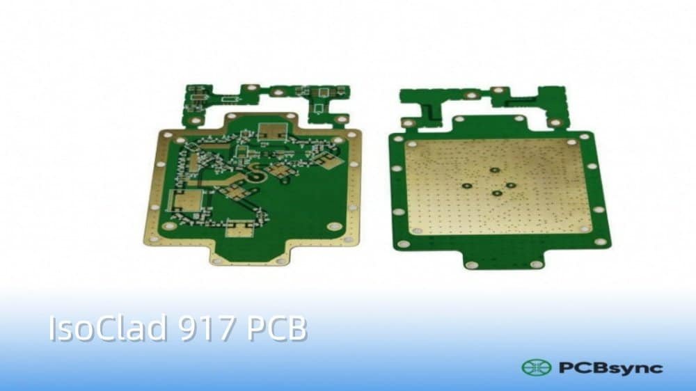
If you’ve ever designed high-frequency circuits for radar systems or conformal antennas, you know the headache of finding a laminate that balances low loss, flexibility, and dimensional stability. I’ve worked with dozens of RF substrates over the years, and IsoClad 917PCB material stands out as one of the go-to choices when you need that combination of ultra-low dielectric constant and the ability to bend your board into shape.
In this guide, I’ll break down everything you need to know about Rogers IsoClad 917 — from its technical specifications to real-world applications — so you can decide if it’s the right fit for your next RF or microwave project.
IsoClad 917 is a non-woven fiberglass reinforced PTFE (polytetrafluoroethylene) composite laminate manufactured by Rogers Corporation. Unlike traditional woven glass laminates, it uses randomly oriented longer fibers combined with PTFE through a proprietary manufacturing process.
This construction gives IsoClad 917 PCB material some unique characteristics that set it apart from other high-frequency substrates:
Ultra-low dielectric constant (Dk): 2.17 or 2.20, among the lowest in its class
Exceptionally low dissipation factor: 0.0013 at 10 GHz
Flexibility: Less rigid than woven fiberglass laminates, allowing the finished PCB to be bent or shaped
Isotropic properties: Consistent electrical behavior across X, Y, and Z axes
The material was originally developed under the Arlon brand before Rogers Corporation acquired it. You’ll sometimes see it referenced as “Arlon IsoClad 917” in older documentation, but it’s the same material.
IsoClad 917 PCB Technical Specifications
When selecting any RF laminate, the specifications matter. Here’s the complete breakdown of IsoClad 917 properties that I reference during my design work.
Electrical Properties
Property
Value
Test Method
Dielectric Constant (Dk)
2.17 ± 0.02 or 2.20
10 GHz
Dissipation Factor (Df)
0.0013
10 GHz
Volume Resistivity
1.5 × 10¹⁰ MΩ-cm
ASTM D-257
Surface Resistivity
1.0 × 10⁹ MΩ
ASTM D-257
Dielectric Breakdown
>45 kV
ASTM D-149
Arc Resistance
>180 seconds
ASTM D-495
The low Dk of 2.17 is what makes IsoClad 917 PCB particularly attractive for antenna designs. Lower dielectric constants mean higher phase velocity, which translates to larger antenna elements for a given frequency — often desirable for achieving specific radiation patterns.
Thermal Properties
Property
Value
Notes
Thermal Coefficient of εr
-157 ppm/°C
-50°C to 150°C range
CTE (X-axis)
46 ppm/°C
-55°C to 288°C
CTE (Y-axis)
47 ppm/°C
-55°C to 288°C
CTE (Z-axis)
236 ppm/°C
-55°C to 288°C
Thermal Conductivity
0.263 W/m·K
at 100°C
One thing to watch: the thermal coefficient of dielectric constant is -157 ppm/°C. That’s higher than some competitors, so if your application sees significant temperature swings, you’ll need to account for Dk drift in your design.
Mechanical Properties
Property
Value
Test Method
Peel Strength (1oz copper)
10 lbs/inch (1.79 N/mm)
After thermal stress
Tensile Modulus
120-133 kpsi
ASTM D-638
Tensile Strength
3.8-4.3 kpsi
ASTM D-638
Flexural Modulus
213 kpsi
ASTM D-790
Compressive Modulus
182 kpsi
ASTM D-695
Density
2.23 g/cm³
ASTM D-792
Environmental & Safety Properties
Property
Value
Water Absorption
0.04%
Flammability Rating
UL94 V-0
Total Mass Loss (Outgassing)
0.02%
Collected Volatile Condensable Material
0.00%
Lead-Free Process Compatible
Yes
The outgassing numbers are critical for aerospace applications. With only 0.02% total mass loss under vacuum conditions, IsoClad 917 PCB material meets the stringent requirements for space-based systems.
Why Choose IsoClad 917 for Your PCB Design?
After working with this material on multiple projects, here are the real-world advantages I’ve found most valuable.
Ultra-Low Loss at High Frequencies
With a dissipation factor of just 0.0013 at 10 GHz, signal attenuation is minimal. This translates directly to:
Better receiver sensitivity in radar systems
Higher antenna efficiency
Reduced power requirements for transmitters
Improved signal-to-noise ratio
For comparison, standard FR-4 has a dissipation factor around 0.02 at similar frequencies — roughly 15 times higher loss.
Flexibility for Conformal Applications
Here’s where IsoClad 917 really shines. The non-woven fiberglass construction makes the finished PCB significantly more pliable than woven-glass alternatives. I’ve successfully used it for:
Wrap-around antennas on cylindrical structures
Conformal arrays that follow curved surfaces
Helmet-mounted antenna systems
Flexible feed networks
You’re not going to roll it up like a flex circuit, but you can bend it to conform to moderate curves without cracking or delaminating.
Superior Dimensional Stability
The longer random fibers in IsoClad 917 provide better dimensional stability compared to chopped-fiber PTFE composites. This matters when you’re:
Etching fine-pitch circuits
Building phase-matched antenna arrays
Designing multi-element feed networks where consistent trace lengths are critical
Isotropic Behavior
Unlike woven glass laminates where the weave pattern can cause directional variations in electrical properties, IsoClad 917’s random fiber orientation provides consistent Dk in all directions. This simplifies design calculations and improves repeatability.
Common Applications for IsoClad 917 PCB
Based on my experience and industry usage, these are the primary applications where IsoClad 917 PCB material excels.
Conformal and Wrap-Around Antennas
This is probably the most common application. When you need an antenna that follows a non-planar surface — like wrapping around a missile body or conforming to an aircraft fuselage — IsoClad 917 is a natural choice.
Stripline and Microstrip Circuits
The low Dk and Df make it excellent for transmission line structures operating in the GHz range. The consistent dielectric properties ensure predictable impedance control.
Radar Systems
Both military and commercial radar applications benefit from the low-loss characteristics. Weather radar, automotive ADAS radar, and aerospace surveillance systems all use materials in this class.
Guidance Systems
Missile guidance and navigation systems require materials that maintain performance across temperature extremes and high-vibration environments. The stability of IsoClad 917 makes it suitable for these demanding applications.
Satellite Communications
The combination of low outgassing and consistent electrical properties makes IsoClad 917 appropriate for space-based communication systems.
Plasma desmear or sodium etch is essential before plating
Hole wall conditioning is critical for reliable plating adhesion
If your fabricator isn’t experienced with PTFE laminates, expect yield issues. Always verify their process capabilities upfront.
Solder Mask Options
Standard solder mask colors are available: green, black, blue, yellow, and red. LPI (liquid photoimageable) masks work well on IsoClad 917 surfaces.
Design Tips for IsoClad 917 PCB Projects
Here are some practical recommendations based on my design experience.
Impedance Calculations
Use the design Dk value of 2.17 in your calculations. For microstrip designs, remember that effective dielectric constant will be lower than substrate Dk due to field fringing into air.
Trace Width Considerations
The low Dk means wider traces for 50Ω impedance compared to higher-Dk materials. For 20 mil IsoClad 917, expect approximately 50-55 mil trace width for 50Ω microstrip (exact value depends on copper weight and stackup).
Thermal Management
With thermal conductivity of only 0.26 W/m·K, heat dissipation can be challenging. For power-handling applications:
Use thermal vias to conduct heat to ground planes
Consider metal backing for high-power amplifiers
Design adequate copper pour areas for heat spreading
Hybrid Stackups
IsoClad 917 can be combined with FR-4 in hybrid multilayer builds using appropriate bondply materials. Rogers’ 3001 Bonding Film and 2929 Bondply are commonly used for this purpose.
Where to Source IsoClad 917 PCB Materials
Manufacturer and Distributors
IsoClad 917 is manufactured exclusively by Rogers Corporation. You can obtain materials and datasheets through:
Rogers Corporation direct sales
Authorized distributors (varies by region)
PCB fabricators who stock the material
PCB Fabrication Services
Several fabricators specialize in high-frequency materials and stock IsoClad 917:
Bicheng Electronics (China) — prototype to production quantities
Modular Components National (USA) — military/aerospace focus
IsoClad 917 has a dielectric constant (Dk) of 2.17 ± 0.02 or 2.20, measured at 10 GHz. This is among the lowest available in reinforced PTFE laminates, making it ideal for applications requiring high phase velocity and minimal signal delay.
Can IsoClad 917 PCB be bent or flexed?
Yes, within limits. The non-woven fiberglass reinforcement makes IsoClad 917 significantly more flexible than woven-glass PTFE laminates. It’s commonly used for conformal antennas that wrap around curved surfaces. However, it’s not a true flex material — expect moderate bending capability, not repeated flexing.
What frequencies is IsoClad 917 suitable for?
IsoClad 917 performs well from UHF through millimeter-wave frequencies. The ultra-low dissipation factor of 0.0013 at 10 GHz makes it particularly suitable for applications in the 1 GHz to 40+ GHz range, including radar, satellite communications, and 5G infrastructure.
How does IsoClad 917 compare to standard FR-4?
IsoClad 917 has roughly 15 times lower loss than FR-4 at high frequencies, a much lower dielectric constant (2.17 vs. ~4.5), and better temperature stability. FR-4 is suitable for digital circuits below 1-2 GHz, while IsoClad 917 is designed for RF/microwave applications where signal integrity is critical.
Is IsoClad 917 suitable for space applications?
Yes. With total mass loss of only 0.02% and zero collected volatile condensable material under vacuum conditions, IsoClad 917 meets outgassing requirements for space-based electronics. It’s used in satellite communication systems and other aerospace applications.
Final Thoughts
IsoClad 917 PCB material occupies a specific niche in the RF laminate world — it’s the material you reach for when you need the lowest possible dielectric constant combined with enough flexibility to conform to curved surfaces. The ultra-low loss and excellent dimensional stability make it a reliable choice for demanding radar, antenna, and guidance system applications.
Is it the right choice for every RF project? No. If you don’t need the flexibility, materials like RT/duroid 5880 may offer even lower loss. If cost is a primary concern and you can tolerate higher Dk, RO4350B might be more practical.
But when the application calls for a bendable, ultra-low-loss, space-qualified laminate — IsoClad 917 is hard to beat.
Have questions about using IsoClad 917 in your design? Drop them in the comments below, or reach out to Rogers’ technical support team for application-specific guidance.
Inquire: Call 0086-755-23203480, or reach out via the form below/your sales contact to discuss our design, manufacturing, and assembly capabilities.
Quote: Email your PCB files to Sales@pcbsync.com (Preferred for large files) or submit online. We will contact you promptly. Please ensure your email is correct.
Notes: For PCB fabrication, we require PCB design file in Gerber RS-274X format (most preferred), *.PCB/DDB (Protel, inform your program version) format or *.BRD (Eagle) format. For PCB assembly, we require PCB design file in above mentioned format, drilling file and BOM. Click to download BOM template To avoid file missing, please include all files into one folder and compress it into .zip or .rar format.


