Inquire: Call 0086-755-23203480, or reach out via the form below/your sales contact to discuss our design, manufacturing, and assembly capabilities.
Quote: Email your PCB files to Sales@pcbsync.com (Preferred for large files) or submit online. We will contact you promptly. Please ensure your email is correct.
Notes: For PCB fabrication, we require PCB design file in Gerber RS-274X format (most preferred), *.PCB/DDB (Protel, inform your program version) format or *.BRD (Eagle) format. For PCB assembly, we require PCB design file in above mentioned format, drilling file and BOM. Click to download BOM template To avoid file missing, please include all files into one folder and compress it into .zip or .rar format.
As a PCB engineer with over a decade in electronics manufacturing, I’ve seen countless boards fail in the field due to one overlooked factor: inadequate insulation resistance testing. The insulation resistance test isn’t just another checkbox on your QA checklist—it’s the difference between a product that lasts years and one that fails within months.
In this comprehensive guide, I’ll walk you through everything you need to know about insulation resistance testing in PCB manufacturing and SMT assembly, from the fundamental principles to advanced testing methods that we use in our production lines daily.
What Is Insulation Resistance Test in PCB Manufacturing?
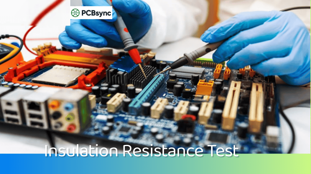
An insulation resistance test measures the resistance of dielectric materials between conductive elements on a printed circuit board. Simply put, it tells you how well your board’s insulation prevents unwanted current flow between traces, layers, and components.
When we apply a DC voltage across two isolated conductors on a PCB, a small amount of current will flow through the insulating material. By measuring this leakage current and applying Ohm’s Law, we calculate the insulation resistance. The higher the value, the better your insulation performs.
Here’s what makes this test critical: modern PCBs feature trace spacing as tight as 75 microns. At these dimensions, even microscopic contamination or material defects can cause leakage currents that lead to signal degradation, power loss, or complete failure.
The underlying physics involves three current components when voltage is applied to an insulator. First, you get capacitive charging current—this starts high and decays rapidly as the dielectric polarizes. Second, absorption current flows as dipoles in the material align with the electric field. Third, and most important for our purposes, is the steady-state leakage current that represents true insulation performance. A proper insulation resistance measurement waits for the first two components to decay before recording the final reading, which is why most standards specify a minimum measurement dwell time.
Understanding this physics helps explain why instantaneous readings differ from stabilized measurements, and why environmental conditions dramatically affect results. The insulation resistance of FR-4, for example, can vary by three orders of magnitude between dry ambient conditions and 85% relative humidity.
Key Parameters Measured During Insulation Resistance Test
Parameter
Description
Typical Values
Surface Insulation Resistance (SIR)
Resistance across the board surface between conductors
≥10^8 Ω (100 MΩ minimum per IPC)
Volume Resistivity
Bulk resistance through the dielectric material
≥10^14 Ω·cm
Leakage Current
Current flowing through insulation under applied voltage
<1 µA (application dependent)
Dielectric Withstanding Voltage
Maximum voltage before breakdown
Typically 2x operating voltage + 1000V
Why Insulation Resistance Testing Matters for PCB Reliability
I’ve performed failure analysis on hundreds of field returns over the years. One pattern emerges repeatedly: boards that passed basic electrical tests but failed insulation resistance testing under environmental stress develop problems within 6-18 months of deployment.
The primary failure mechanisms that insulation resistance testing catches include:
Electrochemical Migration (ECM): This is the silent killer of PCBs. When ionic contamination meets moisture and voltage bias, metal ions migrate from anode to cathode, forming conductive dendrites. These dendrites can bridge traces in milliseconds once they start growing, causing shorts that are nearly impossible to predict without proper SIR testing.
The ECM process follows a predictable sequence: water adsorption on the board surface, dissolution of metal at the anode, ionic transport through the moisture film, and finally reduction and deposition of metal at the cathode. Each step requires specific conditions—remove any one factor (moisture, ions, voltage, susceptible metal) and ECM stops. This is why controlling cleanliness and preventing moisture exposure are both essential strategies.
Silver and tin are particularly susceptible to ECM, which creates challenges as the industry moves toward silver-containing surface finishes and lead-free solders. Boards using immersion silver (ImAg) finish require extra attention to SIR testing because silver’s tendency to form highly conductive dendrites means even small amounts of migration cause immediate shorts.
Conductive Anodic Filamentation (CAF): Unlike surface ECM, CAF occurs within the PCB substrate along glass fiber interfaces. It’s particularly problematic in high-density boards where via-to-via or via-to-trace spacing is minimal. The insulation resistance test, especially under humidity bias conditions, reveals CAF susceptibility before products ship.
CAF happens when copper dissolves at the anode side of a hollow fiber path, migrates along the fiber-resin interface, and deposits at the cathode. The failure appears as a hairline copper filament following the glass weave pattern. Once CAF starts, it’s irreversible—the damage continues even after power is removed.
Design rules that minimize CAF risk include maintaining adequate spacing between vias, avoiding via placement directly at drill entry points where fiber damage is common, and selecting laminates with tight fiber-resin bonding. But even good design can’t completely eliminate CAF risk, which is why testing remains essential.
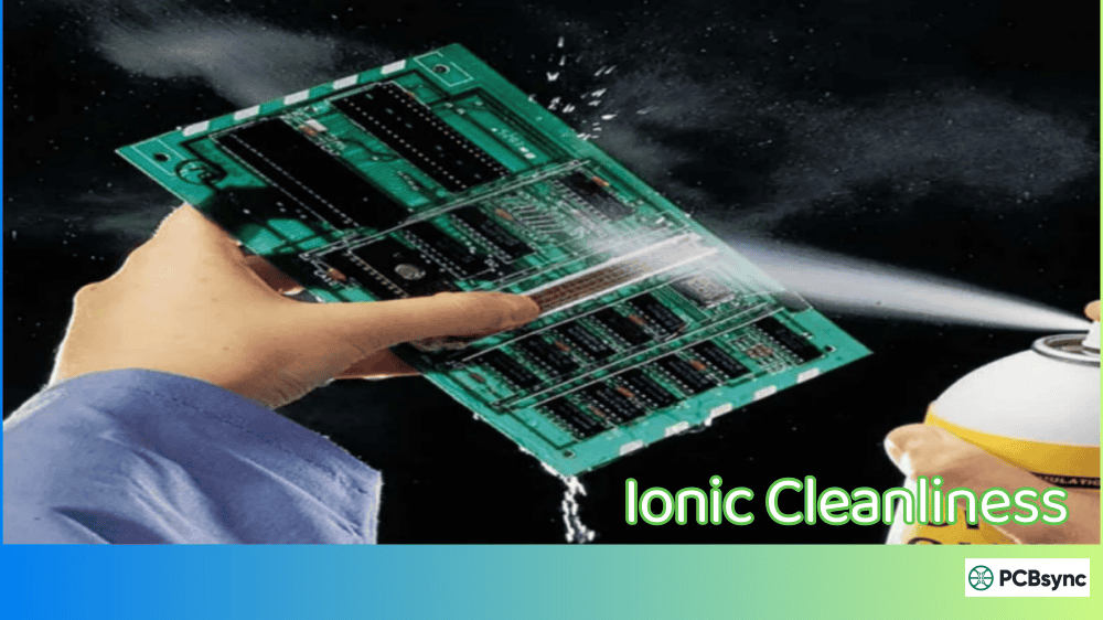
Ionic Contamination: Flux residues, handling contamination, and process chemicals leave ionic residues that become conductive when exposed to humidity. A board might measure perfectly at room temperature but fail dramatically at 85°C/85% RH.
The list of potential ionic contaminants is extensive: chlorides from flux activators and fingerprint sweat, bromides from flame retardants, sulfates from environmental exposure, weak organic acids from flux formulations. Each has different mobility and corrosivity, making contamination source identification a detective exercise combining SIR curves, visual inspection, and chemical analysis.
Read more about PCBSync electronic testing method:
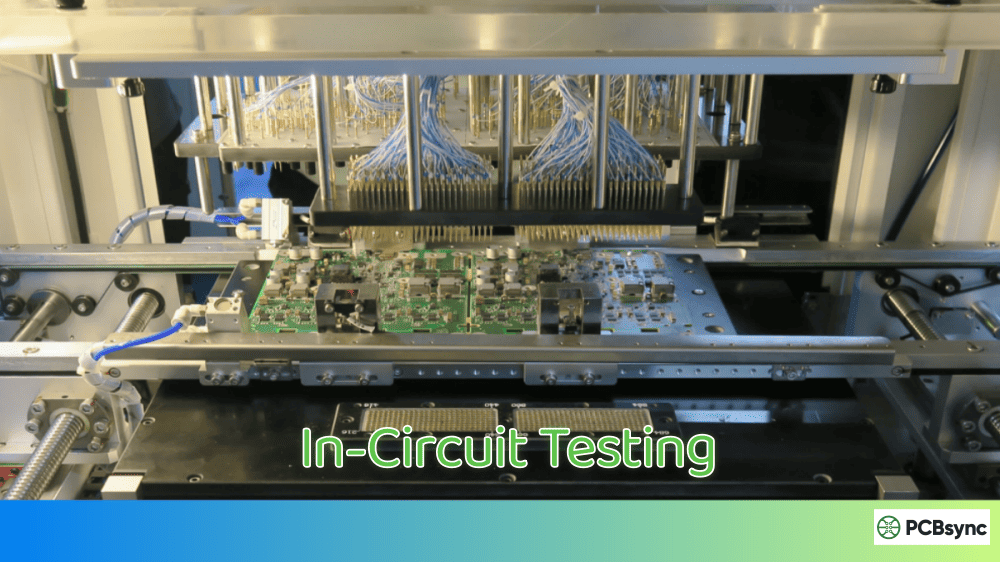
SIR testing has become the gold standard for evaluating assembly cleanliness and long-term reliability. The test uses interdigitated comb patterns—typically the IPC-B-24 or IPC-B-25 test coupons—to simulate the fine-pitch spacing found in modern electronics.
How SIR Testing Works:
The test places samples in a controlled temperature and humidity environment (commonly 40°C/90% RH or 85°C/85% RH) while applying a DC bias voltage between the comb electrodes. Resistance measurements are recorded continuously over 7 days minimum.
What we’re watching for isn’t just the final resistance value—it’s the resistance curve over time. A healthy board maintains stable resistance above 10^8 Ω throughout testing. Boards with contamination issues show declining resistance, sometimes recovering temporarily as dendrites burn off at high voltage, only to fail again.
The comb pattern design deserves attention here. The IPC-B-24 coupon features 0.4mm wide traces with 0.5mm spacing—coarse by today’s standards. For fine-pitch applications, newer 200µm gap patterns more accurately represent actual product geometry. When qualifying processes for BGA or QFP packages with sub-millimeter pitch, consider using test vehicles that match your actual design rules.
One practical consideration often overlooked: component placement affects SIR results significantly. In production, flux gets trapped under components where heat exposure is reduced. Testing bare comb patterns gives optimistic results compared to patterns with representative components mounted. This is why IPC methods now include provisions for testing with QFP devices placed over the comb patterns—the component body shields flux residues from full reflow activation, leaving more active residue on the board surface.
Standard SIR Test Conditions per IPC-TM-650 Method 2.6.3.7:
Parameter
Class 1/2 Conditions
Class 3 (High-Rel) Conditions
Temperature
40°C ± 2°C
85°C ± 2°C
Relative Humidity
90% ± 3%
85% ± 3%
Bias Voltage
45-50 VDC
45-50 VDC
Test Duration
168 hours (7 days)
168 hours minimum
Pass Criteria
≥10^8 Ω
≥10^8 Ω
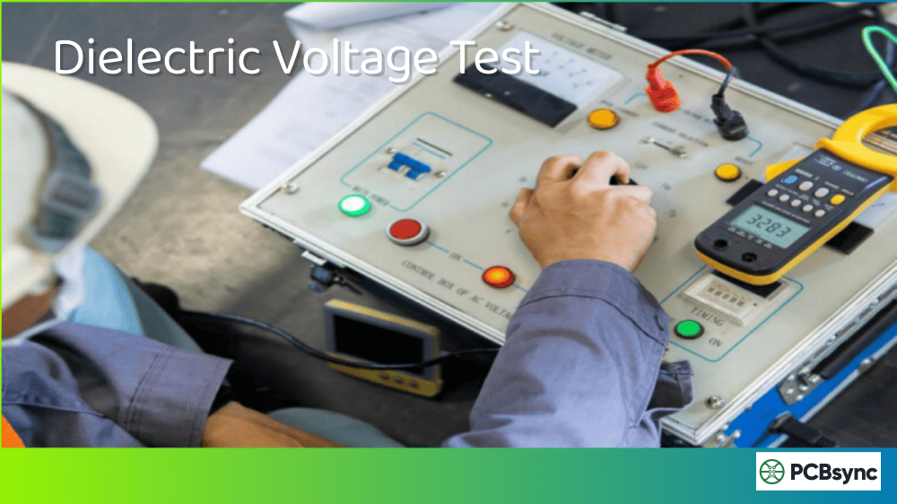
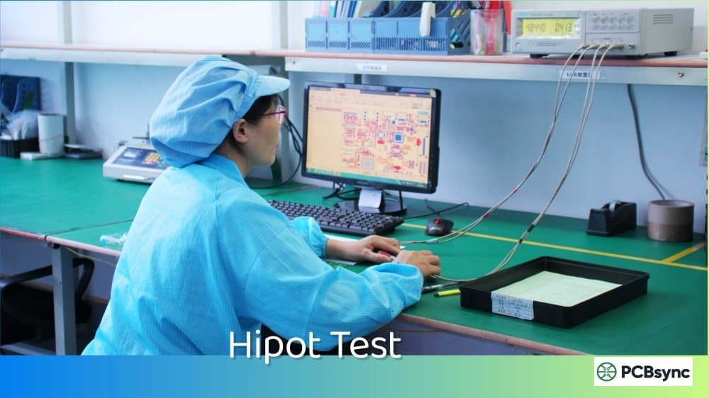
Hi-Pot (Dielectric Withstanding Voltage) Testing
Where SIR testing evaluates long-term reliability under realistic conditions, Hi-Pot testing stresses the insulation to verify it can handle voltage spikes and transients without breakdown.
During Hi-Pot testing, we apply a high voltage (typically 500V to 2500V DC depending on application class) between isolated conductors and measure the resulting leakage current. The test voltage is usually calculated as 2× the maximum operating voltage plus 1000V, held for a specified duration.
A key point many engineers miss: Hi-Pot testing is destructive to marginal insulation. It’s a go/no-go test that catches gross defects but doesn’t predict long-term reliability the way SIR testing does. We use both in our qualification process—Hi-Pot for immediate integrity verification and SIR for reliability prediction.
Temperature Humidity Bias (THB) Testing
THB testing is essentially extended SIR testing under more aggressive conditions, typically running for 1000 hours at 85°C/85% RH with continuous bias. This accelerated life test simulates years of field exposure in weeks.
For automotive, aerospace, and medical applications where field failures are unacceptable, THB testing provides the confidence that SIR testing alone cannot. The extended duration reveals slow-developing failure modes that shorter tests miss.
IPC Standards for Insulation Resistance Testing
Understanding the applicable standards ensures your testing program meets customer requirements and industry expectations. Here’s a breakdown of the key standards every PCB professional should know:
Primary IPC Standards Reference Table
Standard
Title
Application
IPC-TM-650 2.6.3.7
Surface Insulation Resistance
Primary test method for SIR evaluation
IPC-TM-650 2.6.3.3
Moisture and Insulation Resistance, Fluxes
Flux qualification testing
IPC-9201
Surface Insulation Resistance Handbook
Comprehensive SIR testing guidance
IPC-9252
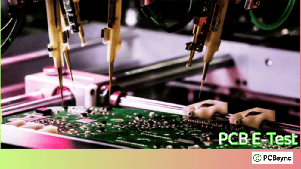
Bare Board Electrical Test Considerations
E-test parameters including IR
IPC-6012
Qualification and Performance Specification for Rigid PCBs
Class-based IR requirements
J-STD-004
Requirements for Soldering Fluxes
Flux SIR requirements
IPC Classification Requirements
IPC defines three product classes with corresponding insulation resistance requirements:
Class 1 (General Electronic Products): Consumer electronics where cosmetic imperfections are acceptable. Insulation resistance minimum is typically 0.5 MΩ at 200 VDC test voltage.
Class 2 (Dedicated Service Electronic Products): Industrial equipment, telecommunications, and business machines requiring extended performance. Minimum insulation resistance is 2 MΩ at 200 VDC.
Class 3 (High-Reliability Electronic Products): Aerospace, military, and medical devices where failure is unacceptable. Testing per IPC-6012 Class 3/A requires 250 VDC test voltage with minimum insulation impedance of 100 MΩ.
Insulation Resistance Test Equipment and Setup
Performing meaningful insulation resistance testing requires appropriate equipment. Here’s what we use in our lab and production environments:
Essential Equipment for IR Testing
Megohmmeters/Insulation Resistance Testers: For basic IR verification, instruments capable of applying 250-1000 VDC and measuring resistance up to 10^12 Ω are essential. Look for instruments with guard terminals to eliminate surface leakage effects.
Automated SIR Test Systems: For production-level SIR testing, automated systems like those from Concoat, ESPEC, or custom-built multi-channel testers provide continuous monitoring of 16-256 channels simultaneously. These systems cost $50,000-$200,000 but are necessary for serious reliability testing programs.
Environmental Chambers: Temperature/humidity chambers capable of maintaining 85°C/85% RH with ±2°C/±3% RH stability. Chamber volume should accommodate your test fixtures with adequate air circulation.
Test Coupons: IPC-B-24 and IPC-B-25 test boards provide standardized comb patterns for flux and process qualification. Custom SIR coupons matching your actual design rules provide more relevant results for specific products.
Test Setup Best Practices
From painful experience, here are the setup details that matter:
Coupon Handling: Always wear gloves. Skin oils and salts dramatically affect SIR results. Store coupons in nitrogen cabinets when not in use.
Connections: Use proper fixtures with spring-loaded contacts. Poor connections introduce noise that masks real SIR behavior.
Grounding: Ground the chamber and test system chassis to prevent common-mode interference.
Data Logging: Log resistance every 5-10 minutes minimum. The shape of the SIR curve matters as much as the final value.
Factors Affecting Insulation Resistance Test Results
Material Properties
The base laminate material significantly impacts insulation resistance. FR-4 provides adequate performance for most commercial applications, but high-reliability designs may require materials with higher Comparative Tracking Index (CTI) ratings.
CTI Ratings and Applications:
CTI Rating
Material Category
Typical Applications
CTI 600+
PLC 0
Harsh environments, outdoor equipment
CTI 400-599
PLC 1
Industrial controls, automotive
CTI 175-399
PLC 2
Consumer electronics, indoor use
CTI 100-174
PLC 3
Controlled environments only
Process Variables
Your manufacturing and assembly processes directly impact insulation resistance:
Flux Residues: No-clean flux doesn’t mean no residue. The remaining residues must be electrically benign. ROL0 (rosin, low-activity) fluxes typically show the best SIR performance. Higher activity fluxes require thorough cleaning.
Reflow Profile: Under-activated flux residues are more corrosive than properly reflowed residues. Ensure your reflow profile achieves complete flux activation—usually requiring 60-90 seconds above liquidus temperature.
Cleaning Process: If cleaning, verify complete residue removal. Partially cleaned boards often perform worse than uncleaned boards because the cleaning process redistributes contamination without removing it.
Storage and Handling: Moisture absorption in bare boards before assembly and contamination from handling both degrade insulation resistance.
Environmental Conditions
Insulation resistance drops exponentially with increasing humidity. A board that measures 10^12 Ω at ambient conditions may drop to 10^8 Ω or lower at 85% RH. Temperature also affects resistance, though less dramatically than humidity.
This is precisely why we test under elevated temperature and humidity—to reveal weaknesses that ambient testing misses.
Best Practices for Insulation Resistance Testing in SMT Assembly
After years of optimizing our testing processes, here are the practices that deliver reliable, meaningful results:
Pre-Assembly Testing
Test incoming bare boards on a sampling basis. Contamination from board fabrication—cleaning chemical residues, handling, storage—can compromise assembly-level SIR before you even start.
We’ve traced several SIR failures back to board suppliers using incompatible cleaning chemicals. One memorable case involved boards that passed all supplier inspections but consistently failed SIR testing after assembly. Root cause analysis revealed residual fluoroboric acid from the HASL process—invisible and undetected by standard ionic contamination testing, but devastating to long-term reliability.
Establish incoming inspection criteria that include SIR testing on a statistical basis, especially when qualifying new board suppliers or receiving boards from facilities you haven’t audited recently.
Process Qualification
When qualifying a new flux, paste, or cleaning process, run full SIR tests using both standard IPC coupons and product-representative test vehicles. The standard coupons establish baseline performance; the product-specific vehicles reveal real-world behavior.
Critical: Test the complete process, not individual materials. Flux A and paste B may individually pass SIR testing but fail when combined due to chemical incompatibility. We learned this the hard way when switching to a new solder paste—the paste manufacturer’s data showed excellent SIR performance, but when combined with our existing rework flux, the mixture created aggressive compounds that failed SIR testing within 24 hours.
Document every parameter of your qualification testing: reflow profile, cleaning parameters, ambient conditions, storage duration before test. You’ll need this information when troubleshooting future issues.
Production Monitoring
For high-reliability production, run SIR monitoring coupons through each batch. These coupons travel through the entire process with production boards, then get submitted for 7-day SIR testing. This catches process drift before it affects product quality.
The cost of running monitoring coupons is trivial compared to the cost of a single field failure investigation or product recall. Budget for continuous SIR monitoring as a quality cost, not an optional expense.
Implement statistical process control on your SIR results. Track trends over time—a gradual decline in average SIR values, even if still passing, indicates process drift that needs attention.
Interpreting Results
Don’t just look at pass/fail. Analyze the SIR curves:
Stable High Resistance (≥10^10 Ω): Excellent. Process is well-controlled.
Gradual Decline Stabilizing Above 10^8 Ω: Acceptable. Some moisture absorption but no active degradation.
Sharp Drops with Recovery: Warning sign. Dendrites are forming and burning off. Reduce contamination sources.
Oscillating Values: Often indicates measurement system issues rather than real board behavior. Check connections, grounding, and instrument calibration before investigating process causes.
Document failures with photographs of the failed coupons under magnification. Dendrite morphology provides clues to the contamination source—copper dendrites look different from tin or silver migration, and the growth direction indicates whether the contamination originated from anode or cathode side chemistry.
Common Insulation Resistance Test Failures and Troubleshooting
When SIR failures occur, follow this diagnostic sequence:
Visual Inspection: Examine failed coupons under 20-50× magnification for dendrites, discoloration, or residue patterns.
SEM/EDS Analysis: If dendrites are present, energy-dispersive X-ray spectroscopy identifies the migrating species (copper, tin, silver) and contaminating ions (chloride, bromide).
Process Audit: Review recent process changes—new flux lot, reflow profile adjustment, cleaning chemical change, different solder paste supplier.
Useful Resources and Standards Downloads
For engineers implementing or improving insulation resistance testing programs, these resources are invaluable:
IPC Standards and Test Methods
IPC-TM-650 Test Methods Manual: Available from IPC at www.ipc.org. Contains all standard test methods including 2.6.3.3 and 2.6.3.7 for SIR testing.
IPC-9201 Surface Insulation Resistance Handbook: Comprehensive guidance on SIR testing methodology, equipment, and interpretation.
IPC-B-24 Test Board Kit: Standardized SIR test coupons available from IPC-authorized distributors.
Technical References
NPL Report CMMT(A)48: “Surface Insulation Resistance Measurements: A Review” – Excellent technical review of SIR methodology from the UK National Physical Laboratory.
ASTM D257: Standard test methods for DC resistance of insulating materials – Referenced by IPC methods for measurement procedures.
Industry Organizations
IPC (Association Connecting Electronics Industries): www.ipc.org – Standards, training, and industry networking.
SMTA (Surface Mount Technology Association): www.smta.org – Technical conferences and published research.
Equipment Suppliers
Leading suppliers of SIR test equipment include ESPEC, Thermotron, Cincinnati Sub-Zero (environmental chambers), and specialty electronics test equipment manufacturers. Request application-specific configurations for SIR testing.
Frequently Asked Questions About Insulation Resistance Test
What is the minimum acceptable insulation resistance for PCBs?
Per IPC standards, the minimum acceptable insulation resistance is 10^8 Ω (100 MΩ) for SIR testing under standard conditions. For bare board electrical testing, IPC-9252 specifies minimum values based on product class: 0.5 MΩ for Class 1, 2 MΩ for Class 2, and 100 MΩ for Class 3/A aerospace applications. However, these are minimums—we typically target 10^9 Ω or higher for reliable products.
How long should an insulation resistance test run?
Standard SIR testing per IPC-TM-650 2.6.3.7 runs for a minimum of 168 hours (7 days). For high-reliability applications, THB testing extends to 1000 hours. Quick-look tests at 24-48 hours can provide early indications but don’t replace full-duration testing. Dendrite formation and some contamination effects may not manifest until 72-96 hours into testing.
What voltage should be used for insulation resistance testing?
For SIR testing, IPC specifies 45-50 VDC bias during environmental exposure, with 100 VDC applied for actual resistance measurements. For Hi-Pot testing, use 2× maximum operating voltage plus 1000V, or follow the specific requirement in your product specification. Note that higher test voltages can destroy forming dendrites, potentially masking real problems—this is why IPC specifies lower bias voltages for SIR testing.
Can insulation resistance testing damage the PCB?
Standard SIR testing at 50 VDC bias is non-destructive and boards can be used normally after testing. Hi-Pot testing at high voltages (500V+) can damage marginal insulation, which is actually the point—to identify weak spots before field deployment. Boards that pass Hi-Pot testing are not damaged by the experience. However, don’t repeatedly Hi-Pot test the same board, as cumulative stress can degrade insulation over time.
What causes sudden drops in insulation resistance during testing?
Sudden SIR drops indicate dendrite formation bridging the test electrodes. This typically occurs when ionic contamination (from flux residues, handling, or process chemicals) combines with moisture and electrical bias to enable electrochemical migration. The resistance may recover if the dendrite burns off at high voltage, but this indicates a serious reliability risk. Investigate contamination sources and process controls immediately when this pattern appears.
Conclusion
The insulation resistance test stands as one of the most important quality assurance tools in PCB manufacturing and SMT assembly. It reveals contamination issues, material defects, and process problems that other tests miss—problems that inevitably surface as field failures if not caught during production.
Whether you’re qualifying a new flux formulation, monitoring production cleanliness, or investigating field returns, understanding insulation resistance testing methodology helps you build more reliable products. The investment in proper SIR testing equipment and procedures pays dividends through reduced warranty costs and improved customer satisfaction.
Start by reviewing your current test coverage against the IPC standards outlined here. If you’re not running SIR tests on new processes or monitoring production with test coupons, you’re likely shipping boards with latent reliability issues. The time to find these problems is in your facility, not in your customer’s products.
For specific questions about implementing insulation resistance testing in your operation, reach out to your test equipment supplier or consult the IPC standards library. The resources exist to help you build a robust testing program—use them.
Inquire: Call 0086-755-23203480, or reach out via the form below/your sales contact to discuss our design, manufacturing, and assembly capabilities.
Quote: Email your PCB files to Sales@pcbsync.com (Preferred for large files) or submit online. We will contact you promptly. Please ensure your email is correct.
Notes: For PCB fabrication, we require PCB design file in Gerber RS-274X format (most preferred), *.PCB/DDB (Protel, inform your program version) format or *.BRD (Eagle) format. For PCB assembly, we require PCB design file in above mentioned format, drilling file and BOM. Click to download BOM template To avoid file missing, please include all files into one folder and compress it into .zip or .rar format.


