Inquire: Call 0086-755-23203480, or reach out via the form below/your sales contact to discuss our design, manufacturing, and assembly capabilities.
Quote: Email your PCB files to Sales@pcbsync.com (Preferred for large files) or submit online. We will contact you promptly. Please ensure your email is correct.
Notes: For PCB fabrication, we require PCB design file in Gerber RS-274X format (most preferred), *.PCB/DDB (Protel, inform your program version) format or *.BRD (Eagle) format. For PCB assembly, we require PCB design file in above mentioned format, drilling file and BOM. Click to download BOM template To avoid file missing, please include all files into one folder and compress it into .zip or .rar format.
When I first started working on industrial PCB projects over a decade ago, I quickly learned that consumer-grade boards simply won’t cut it in demanding environments. Industrial PCB manufacturing requires a completely different mindset—one focused on long-term reliability, extreme condition tolerance, and zero-failure performance. Whether you’re designing control systems for factory automation, power electronics for renewable energy, or avionics for aerospace applications, understanding what makes industrial PCBs different is essential for project success.
In this comprehensive guide, I’ll walk you through everything you need to know about industrial PCB manufacturing, from material selection and international standards to quality testing methods that separate professional-grade boards from the rest.
What Makes Industrial PCB Different from Consumer PCB?
Before diving into specifications, let’s clarify what we mean by “industrial PCB.” These aren’t just regular circuit boards with a fancy label—they’re specifically engineered to operate reliably under conditions that would destroy standard boards within months or even weeks.
Industrial PCBs typically need to handle:
Wide temperature ranges: Operating from -40°C to +125°C without performance degradation
Extended service life: 10+ years of continuous operation versus 2-5 years for consumer boards
Mechanical stress: Vibration resistance (10-2000Hz), shock resistance (up to 50G)
Environmental hazards: Moisture, dust, chemical exposure, and salt spray
The key difference comes down to reliability class. Consumer electronics generally use IPC Class 1 or Class 2 standards, which allow for some cosmetic defects and wider tolerances. Industrial PCBs demand IPC Class 2 or Class 3 compliance, where every solder joint, trace width, and plating thickness meets stringent acceptance criteria.
Industrial PCB Applications Across Industries
Industrial PCBs serve as the backbone of mission-critical electronic systems across numerous sectors. Understanding these applications helps clarify why the manufacturing requirements are so demanding.
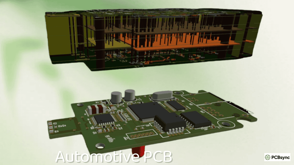
Automotive Electronics
Modern vehicles contain dozens of industrial PCBs managing everything from powertrain control units to Advanced Driver Assistance Systems (ADAS). These boards face constant vibration from the road, temperature swings from engine heat to winter cold, and exposure to automotive fluids. Electric vehicle powertrains push these requirements even further with high-current demands and thermal management challenges.
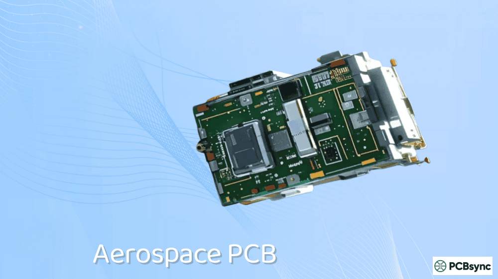
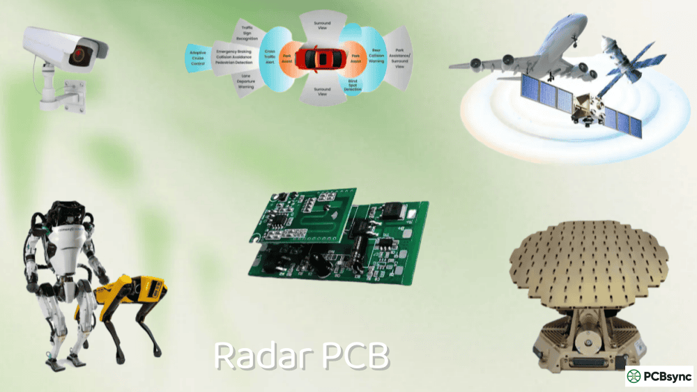
Aerospace and Defense
Satellite communication equipment, avionics systems, and military electronics represent some of the most demanding industrial PCB applications. These boards must withstand vacuum environments, radiation exposure, extreme temperature cycling, and years of operation without possibility of repair. Standards like IPC 6012DS (space/military addendum) and MIL-PRF-31032 govern these applications.
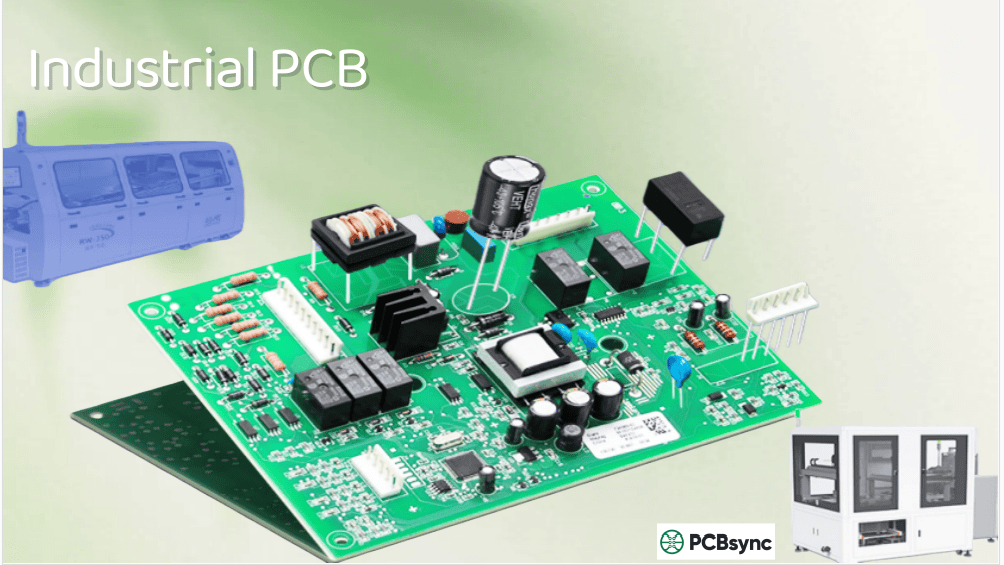
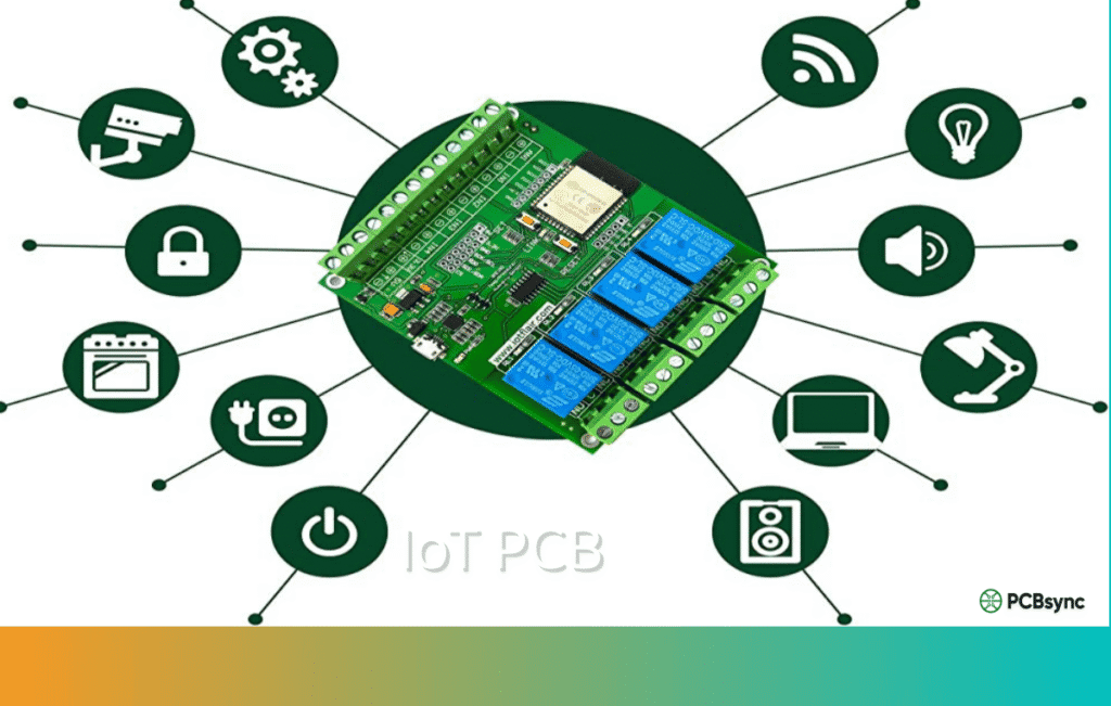
Industrial Automation
Programmable Logic Controllers (PLCs), sensor modules, and motor drives form the nervous system of modern factories. These industrial PCBs operate 24/7 in environments with electrical noise, dust, vibration, and temperature fluctuations. Reliability isn’t optional—a single board failure can halt production lines costing thousands per hour in downtime.
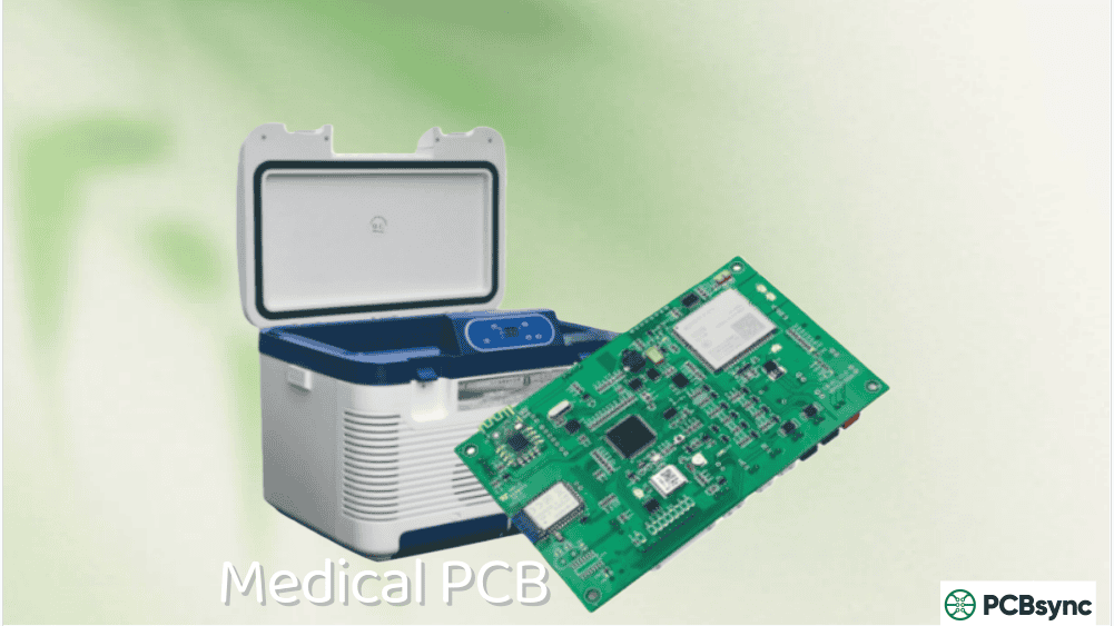
Medical Devices
From diagnostic imaging equipment to implantable devices, medical industrial PCBs require exceptional reliability and must meet ISO 13485 certification. Patient safety depends on these boards functioning perfectly, making quality control paramount.
Energy Systems
Solar inverters, wind turbine controllers, and power grid management systems use industrial PCBs designed for outdoor harsh environment adaptation. These applications combine high power handling with exposure to weather extremes and long service life requirements.
Industrial PCB Materials: Choosing the Right Substrate
Material selection is arguably the most critical decision in industrial PCB manufacturing. The substrate determines thermal performance, mechanical strength, electrical characteristics, and ultimately, board longevity.
FR-4: The Workhorse Material
Standard FR-4 remains the most commonly used substrate for industrial PCBs, and for good reason. This glass fiber reinforced epoxy laminate offers an excellent balance of mechanical strength, electrical insulation, and cost-effectiveness. However, not all FR-4 is created equal.
Standard FR-4 works well for general industrial applications with operating temperatures up to 130°C. The glass transition temperature (Tg)—the point where the material begins softening—typically ranges from 130-140°C.
High-Tg FR-4 uses advanced resin systems to push the glass transition temperature above 170°C, sometimes reaching 180°C or higher. This is essential for lead-free soldering processes and applications where the PCB operates near its thermal limits. For any industrial application, I always recommend high-Tg FR-4 as the baseline specification.
Halogen-Free FR-4eliminates bromine-based flame retardants, meeting environmental regulations like RoHS and REACH while maintaining fire resistance. This variant is increasingly specified for applications where toxic fumes during potential fire events pose safety concerns.
Polyimide: The Flexibility Champion
When your industrial PCB needs to bend, twist, or fit into tight spaces while withstanding extreme temperatures, polyimide is the answer. This material handles operating temperatures up to 260°C and offers exceptional chemical resistance.
High-temperature environments like engine compartments
Applications with repeated mechanical flexing
The trade-off is cost—polyimide substrates typically run 3-5 times more expensive than standard FR-4. But for the right application, this premium buys reliability that no other material can match.
Metal Core PCB: Thermal Management Solution
Industrial applications with high power dissipation—LED lighting systems, motor drivers, power supplies—often require metal core PCBs (MCPCBs). These use an aluminum or copper base layer that conducts heat away from components far more effectively than traditional substrates.
For high-power industrial PCB designs, metal cores can mean the difference between reliable operation and premature component failure from thermal stress.
Ceramic Substrates: The Premium Option
When thermal conductivity, mechanical stability, and high-frequency performance all matter, ceramic substrates deliver. Materials like alumina (Al₂O₃) and aluminum nitride (AlN) offer thermal conductivity ranging from 20-170 W/m·K while maintaining excellent electrical properties.
Ceramic industrial PCBs find use in:
High-power RF and microwave circuits
IGBT power modules
Military and aerospace systems
Medical implantable devices
The cost and manufacturing complexity of ceramic PCBs limit their use to applications where no other material will suffice.
International standards ensure that industrial PCBs meet consistent quality requirements regardless of where they’re manufactured. The IPC (Association Connecting Electronics Industries) maintains the primary standards governing PCB design, fabrication, and assembly.
IPC-2221: Generic Design Standard
This foundational standard covers general PCB design requirements including material selection, conductor spacing, hole sizes, and mechanical tolerances. Every industrial PCB design should reference IPC-2221 as the starting point for layout rules.
Key considerations from IPC-2221 include:
Minimum conductor spacing based on voltage levels
Recommended copper weights for current carrying requirements
Via design specifications and aspect ratios
Environmental considerations for material selection
IPC-6012: Qualification and Performance for Rigid PCBs
IPC-6012 defines quality and performance standards for rigid printed circuit boards, establishing three classes of acceptance criteria:
Class 1 – General Electronic Products: Consumer electronics where cosmetic appearance and limited life expectancy are acceptable.
Class 2 – Dedicated Service Electronic Products: Industrial equipment, communications systems, and business machines requiring extended life and reliable performance.
Class 3 – High-Performance Electronic Products: Medical, aerospace, military, and life-support systems where continuous operation and zero-failure performance are critical.
For industrial PCB manufacturing, Class 2 represents the minimum acceptable standard, with many applications requiring Class 3 compliance.
IPC-A-600: Acceptability of Printed Boards
This visual acceptance standard provides detailed criteria for evaluating bare PCB quality. Inspectors use IPC-A-600 to determine whether finished boards meet specified requirements before assembly. The standard covers:
Quality Control and Testing Methods for Industrial PCB
Rigorous testing separates reliable industrial PCBs from those that will fail in the field. A comprehensive quality control program incorporates multiple inspection and test methods at various production stages.
Automated Optical Inspection (AOI)
AOI systems use high-resolution cameras and sophisticated algorithms to scan PCB surfaces, detecting defects that human inspectors might miss. This non-contact inspection method identifies:
Component placement errors (missing, rotated, or misaligned)
Solder bridge and insufficient solder
Polarity violations
Surface contamination
Trace defects and scratches
Modern 3D AOI systems use laser triangulation to measure component height and coplanarity, catching issues that 2D systems cannot detect. For industrial PCB production, AOI typically occurs after solder paste printing and again after reflow soldering.
X-Ray Inspection (AXI)
Components like Ball Grid Arrays (BGAs), QFNs, and bottom-termination devices hide their solder joints beneath the package where optical inspection cannot see. Automated X-ray inspection penetrates these packages to reveal:
Solder ball voids and defects
Head-in-pillow failures
Bridging between adjacent balls
Insufficient or excessive solder volume
For industrial PCBs using high-density interconnects or power modules with hidden connections, X-ray inspection is not optional—it’s essential for quality assurance.
In-Circuit Testing (ICT)
ICT uses a “bed-of-nails” fixture to simultaneously contact test points across the assembled board, performing electrical measurements to verify:
Component presence and correct values
Short circuits and open connections
Semiconductor junction functionality
Resistance, capacitance, and inductance measurements
The custom fixtures required for ICT represent significant tooling investment, making this method most economical for high-volume industrial PCB production where the per-unit cost amortizes across thousands of boards.
Successful industrial PCB manufacturing starts with design decisions that enable reliable production. DFM analysis catches potential issues before fabrication begins, saving time and money while improving yield.
Trace Width and Spacing
Industrial applications often require tighter tolerances than consumer products. Minimum trace width depends on current carrying requirements, manufacturing capability, and IPC class:
Class 2: Minimum 0.1mm (4 mil) trace and space
Class 3: Minimum 0.075mm (3 mil) with advanced processes
Always design with manufacturing margins—if your process minimum is 4 mil, design with 5-6 mil where possible to improve yield.
Via Design
Aspect ratio (board thickness divided by hole diameter) significantly impacts plating quality and reliability:
Standard: 8:1 aspect ratio
Advanced: 10:1 for high-reliability industrial PCBs
Microvias: 0.75:1 for HDI designs
Specify via fill or plug requirements for any vias under components, particularly BGAs where open vias can cause solder wicking.
Useful Resources for Industrial PCB Engineers
Standards and Specifications
IPC Standards Store: www.ipc.org/standards – Official source for all IPC standards
IPC-2221 Free Preview: Available through IPC website for members
IEEE: Technical papers and standards for specialized applications
Frequently Asked Questions About Industrial PCB
What is the typical lifespan of an industrial PCB?
Industrial PCBs designed and manufactured to IPC Class 3 standards typically achieve 10+ years of continuous operation, compared to 2-5 years for consumer-grade boards. Actual lifespan depends on operating conditions, thermal management, and environmental exposure. Proper material selection and manufacturing quality are the primary factors determining longevity.
How do I choose between FR-4 and polyimide for my industrial application?
Choose high-Tg FR-4 when your application operates below 150°C, doesn’t require flexibility, and cost is a consideration. Select polyimide when you need flexible circuits, operating temperatures above 150°C, superior chemical resistance, or applications in aerospace/defense where the premium cost is justified by reliability requirements.
What IPC class should I specify for industrial PCB manufacturing?
Most industrial applications require IPC Class 2 as a minimum, which covers dedicated service electronics with extended life requirements. Specify IPC Class 3 for medical devices, aerospace, military, or any application where failure could result in safety hazards or significant financial consequences. Class 3 costs more but provides the highest reliability assurance.
Why is X-ray inspection necessary for industrial PCB assembly?
X-ray inspection is essential whenever your design uses Ball Grid Arrays (BGAs), Quad Flat No-Lead (QFN) packages, or other components with hidden solder joints. These connections cannot be visually inspected after assembly, and defects like voids, bridging, or head-in-pillow failures would go undetected without X-ray capability. For industrial reliability, this inspection is non-negotiable.
How does conformal coating improve industrial PCB reliability?
Conformal coating applies a thin protective layer over assembled boards, providing protection against moisture, dust, chemicals, and temperature extremes. For industrial environments with contamination risks, conformal coating can extend board life significantly by preventing corrosion and electrical leakage. Common coating materials include acrylic, silicone, urethane, and parylene, each suited to different environmental challenges.
Conclusion: Building Reliable Industrial PCBs
Industrial PCB manufacturing demands attention to every detail—from initial material selection through final functional testing. The standards, materials, and quality processes discussed in this guide represent hard-won industry knowledge developed over decades of real-world experience.
When specifying your next industrial PCB project, remember these key principles:
Match materials to your operating environment: High-Tg FR-4 minimum, specialty materials when conditions demand
Specify appropriate IPC class: Class 2 for general industrial, Class 3 for critical applications
Implement comprehensive testing: AOI, X-ray, and electrical testing appropriate to production volume
Design for manufacturing: Work with your fabricator to optimize designs for reliable production
Document everything: Complete specifications prevent misunderstandings and ensure repeatability
The investment in proper industrial PCB manufacturing pays dividends in reduced field failures, lower warranty costs, and the reputation that comes from delivering reliable products. In industrial applications, quality isn’t just a feature—it’s the fundamental requirement.
Inquire: Call 0086-755-23203480, or reach out via the form below/your sales contact to discuss our design, manufacturing, and assembly capabilities.
Quote: Email your PCB files to Sales@pcbsync.com (Preferred for large files) or submit online. We will contact you promptly. Please ensure your email is correct.
Notes: For PCB fabrication, we require PCB design file in Gerber RS-274X format (most preferred), *.PCB/DDB (Protel, inform your program version) format or *.BRD (Eagle) format. For PCB assembly, we require PCB design file in above mentioned format, drilling file and BOM. Click to download BOM template To avoid file missing, please include all files into one folder and compress it into .zip or .rar format.


