Inquire: Call 0086-755-23203480, or reach out via the form below/your sales contact to discuss our design, manufacturing, and assembly capabilities.
Quote: Email your PCB files to Sales@pcbsync.com (Preferred for large files) or submit online. We will contact you promptly. Please ensure your email is correct.
Notes: For PCB fabrication, we require PCB design file in Gerber RS-274X format (most preferred), *.PCB/DDB (Protel, inform your program version) format or *.BRD (Eagle) format. For PCB assembly, we require PCB design file in above mentioned format, drilling file and BOM. Click to download BOM template To avoid file missing, please include all files into one folder and compress it into .zip or .rar format.
If you’ve spent any time troubleshooting modern electronics, you’ve probably encountered a failed BGA chip. Maybe it’s a laptop GPU showing artifacts, a gaming console with the dreaded red ring, or a smartphone that refuses to boot. The culprit is often the tiny solder balls hiding beneath these chips—and the solution is IC reballing.
I’ve been working with PCBs for over a decade, and I can tell you that mastering BGA reballing has saved me (and my clients) thousands of dollars in replacement parts. This isn’t some mystical dark art—it’s a learnable skill that any serious electronics technician should have in their toolkit.
In this guide, I’ll walk you through everything you need to know about reballing integrated circuits, from understanding why solder joints fail to executing a successful reball on CPUs, GPUs, and other BGA components. Whether you’re repairing an iPhone audio IC or replacing solder balls on an Xbox GPU, this guide has you covered.
What is IC Reballing and Why Does It Matter?
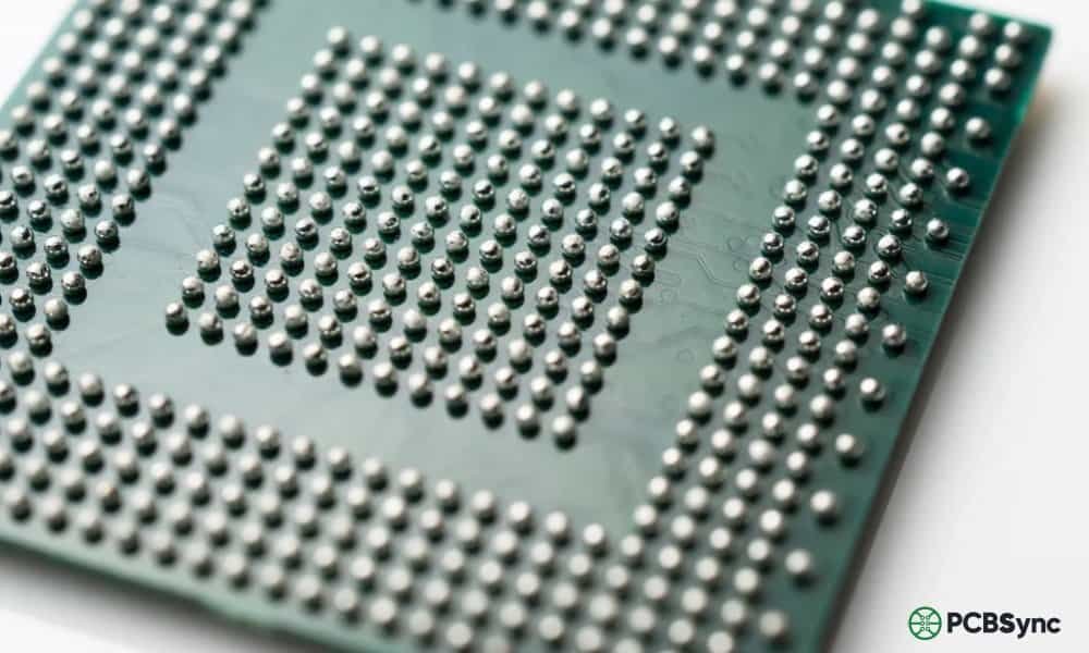
IC reballing refers to the process of removing an integrated circuit from a circuit board, cleaning the old solder residue, applying new solder balls using a stencil, and then reinstalling the chip onto the PCB. It’s essentially giving your chip a fresh set of electrical connections.
The term gets used interchangeably with BGA reballing because most chips that require this procedure use Ball Grid Array packaging. Unlike older chip packages with visible leads on the sides, BGAs have their connections hidden underneath—an array of tiny solder spheres that connect the chip to the board.
Why Solder Balls Fail
Here’s what actually happens to cause these failures:
Thermal cycling is the main killer. Every time your device heats up during use and cools down when idle, the solder joints expand and contract. Over thousands of cycles, microscopic cracks form. Eventually, these cracks propagate until the electrical connection breaks.
Mechanical stress from drops, flexing, or vibration accelerates the problem. Laptops are particularly vulnerable—every time you pick one up by the corner, you’re flexing the motherboard and stressing those solder joints.
Lead-free solder made things worse. After environmental regulations forced manufacturers to switch from tin-lead solder to lead-free alternatives around 2006, reliability dropped significantly. Lead-free solder is more brittle and forms weaker joints that crack more easily under thermal stress.
Manufacturing defects also play a role. Cold solder joints, insufficient reflow temperatures, and contamination during PCB assembly can all create weak connections from day one.
BGA Reballing vs. Reflowing: Understanding the Difference
Before we go further, let’s clear up a common point of confusion. Reballing and reflowing are not the same thing, and knowing when to use each technique matters.
Aspect
Reflowing
Reballing
Process
Heat the chip in place to melt and reform existing solder
Remove chip, replace all solder balls, reinstall
Time Required
15-30 minutes
1-3 hours
Equipment Cost
Low ($50-200)
Medium-High ($200-1000+)
Success Rate
Variable (weeks to months)
High (years if done properly)
Skill Level
Beginner-Intermediate
Intermediate-Advanced
Best For
Temporary fixes, diagnosis
Permanent repairs, chip transplants
Reflowing simply reheats the existing solder to reform the joints. It’s faster and requires less equipment, but it’s fundamentally a temporary fix. You’re working with the same compromised solder that already failed once. In my experience, reflowed chips typically fail again within weeks to months, especially under heavy use.
BGA reballing removes the old solder entirely and replaces it with fresh solder balls. When done correctly with quality materials, a reballed chip should last as long as a factory-new component. It’s more work, but it’s the only real repair.
Here’s my rule of thumb: Use reflow for diagnosis (confirming the chip is the problem) or emergency situations where you need a device working temporarily. Use reballing for any repair you expect to last.
Essential Tools and Equipment for IC Reballing
Let me break down what you actually need to get started with IC reballing. I’ll separate the must-haves from the nice-to-haves.
Core Equipment
Tool
Purpose
Budget Option
Professional Option
Hot Air Station
Chip removal and reflow
Yihua 8858 ($40-60)
Quick 861DW ($300+)
Preheater
Bottom heat for PCB
T-8280 IR Preheater ($80-120)
Infrared rework station ($500+)
BGA Stencils
Solder ball placement
Universal stencil kit ($20-50)
Chip-specific stencils ($5-15 each)
Reballing Jig/Station
Holds chip and stencil aligned
Basic holder ($15-30)
Precision reballing station ($100-300)
Solder Balls
The actual solder spheres
Leaded (Sn63/Pb37) assortment ($15-30)
Matched alloy balls ($20-50)
Flux
Facilitates solder flow
Amtech NC-559-V2 ($15-25)
Kester 951 ($20-40)
Soldering Iron
Pad cleaning, touch-up work
Hakko FX-888D ($100)
JBC or Metcal ($400+)
Support Tools
Microscope or magnifying lamp – You cannot do quality reballing work without magnification. A 10-40x stereo microscope is ideal.
Tweezers – Fine-point ESD-safe tweezers for handling chips and solder balls
Vacuum pickup pen – For safely lifting and placing chips
Solder wick/desoldering braid – Essential for cleaning old solder from pads
Isopropyl alcohol (99%) – For cleaning flux residue
Kapton tape – Heat-resistant tape to mask off surrounding components
Thermocouple – For monitoring actual temperature on the chip/board
Lint-free wipes – For cleaning without leaving fibers
Solder Ball Sizes: Quick Reference
Different chips require different ball sizes. Here are the most common:
Ball Diameter
Typical Applications
0.2mm – 0.3mm
Mobile phone ICs, small BGAs
0.35mm – 0.4mm
NAND flash, memory chips
0.45mm – 0.5mm
Mid-size BGAs, some GPUs
0.5mm – 0.6mm
CPU, GPU, larger BGAs
0.6mm – 0.76mm
Large BGAs, gaming console chips
When in doubt, measure the original solder ball diameter or check the chip’s datasheet. Using balls that are too large causes bridging; too small results in weak joints.
BGA Reballing Process: Step-by-Step Tutorial
Now let’s get into the actual reballing process. I’ll break this down into phases so you can follow along whether you’re reballing a smartphone IC or a laptop GPU.
Phase 1: Preparation and Chip Removal
Step 1: Document everything
Before touching anything, photograph the board from multiple angles. Note the chip orientation—most BGAs have a pin 1 indicator (dot, notch, or corner mark). Reversing a chip during reinstallation is a common and fatal mistake.
Step 2: Protect surrounding components
Apply Kapton tape over any nearby components that might be affected by heat, especially plastic connectors, batteries, or low-melting-point parts. Cover the area around your target chip, leaving only the chip exposed.
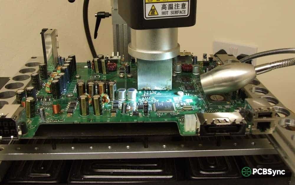
Step 3: Set up your heating equipment
Position your preheater beneath the board. Set it to 100-150°C to bring the entire board up to temperature gradually. This reduces thermal shock and helps the top-side heat penetrate more evenly.
Step 4: Remove the chip
Apply flux around the edges of the chip—this helps heat transfer and indicates when the solder melts (the chip will shift slightly). Using your hot air station:
Lead-free solder: Target 245-260°C air temperature
Leaded solder: Target 220-240°C air temperature
Heat the chip evenly, moving in a circular pattern. Most chips take 2-4 minutes to reach reflow temperature. When the solder liquefies, you’ll see the chip “float” slightly. Use your vacuum pickup or tweezers to lift it straight up.
Critical warning: Never pry or twist a chip that isn’t fully reflowed. You will rip pads off the PCB.
Phase 2: Cleaning and Inspection
Step 5: Clean the chip
This is where most failures happen. Rushed cleaning leads to uneven surfaces, which leads to failed reballs.
With the chip on a heat-resistant surface, apply flux and use a clean soldering iron tip to wick away old solder. Work systematically across all pads:
Tin your soldering iron tip
Apply flux to a section of pads
Drag the iron tip across the pads
Use solder wick to absorb excess solder
Repeat until pads are flat and shiny
Inspect under magnification. Every pad should be uniformly flat with no solder mounds or bridges. Clean off all flux residue with isopropyl alcohol.
Step 6: Clean the PCB pads
Follow the same process on the board. Be extra careful here—PCB pads are more fragile than chip pads. Use minimal pressure with the solder wick to avoid lifting pads.
Step 7: Inspect for damage
Before proceeding, check both the chip and PCB for:
Lifted or missing pads
Damaged solder mask
Cracks in the chip package
Burnt or discolored areas
Any lifted pads need to be repaired before continuing. Proceeding with damaged pads guarantees failure.
Phase 3: Applying New Solder Balls
Step 8: Set up your reballing station
Place your clean chip in the reballing jig, component side down (pads facing up). Select the appropriate stencil—it should match your chip’s ball pattern and size.
Step 9: Apply flux to the chip
Apply a thin, even layer of flux to the pad side of the chip. Too much flux causes balls to float and misalign; too little prevents proper adhesion.
Step 10: Position the stencil
Align the stencil over the chip so that every hole lines up with a pad. Most stencils have alignment features to help with this. Lock the stencil in place.
Step 11: Place solder balls
Pour solder balls onto the stencil. Use a small tool or gentle shaking to guide balls into every hole. Remove excess balls. Check under magnification that every hole contains exactly one ball.
Step 12: Reflow the balls
You have two options here:
Direct heat method: Use your hot air station to heat the chip through the stencil. Watch the flux—when it starts to smoke and the balls become shiny/spherical, they’ve reflowed. Remove heat immediately.
Oven method: Place the chip/stencil assembly on a hotplate or in a reflow oven. Follow your solder’s reflow profile. This gives more even results but requires careful temperature control.
Step 13: Remove stencil and inspect
Let the chip cool to around 100°C (warm but touchable). Carefully separate the stencil from the chip. Inspect every ball under magnification:
All balls should be present and uniform in size
No bridges between adjacent balls
Balls should be centered on their pads
Surface should be smooth and shiny (leaded) or slightly matte (lead-free)
Clean any flux residue with isopropyl alcohol.
Phase 4: Reinstallation
Step 14: Prepare the PCB
Apply fresh flux to the PCB pads where the chip will be installed. Use a thin, even layer.
Step 15: Place the chip
Using your vacuum pickup tool, position the chip over its footprint. Align the pin 1 indicator with the corresponding mark on the PCB. Set the chip down gently—the flux will hold it in place.
Step 16: Reflow the chip onto the board
Heat the board from below with your preheater (100-150°C). Apply top heat with your hot air station following the same temperature guidelines as removal.
Watch for the chip to settle slightly as the solder balls melt and self-center (this is called “self-alignment” and is one of BGA’s advantages). Once you see this settling motion, hold temperature for 10-15 seconds, then remove heat and allow slow cooling.
Step 17: Final inspection and cleaning
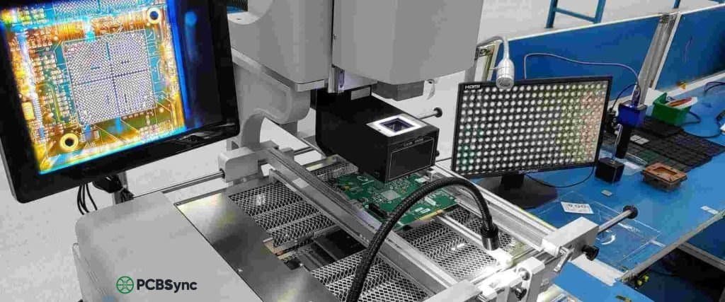
Clean all flux residue from around the chip. Inspect the perimeter balls under magnification—you should see consistent solder fillets where balls meet pads. If available, X-ray inspection can verify internal joint quality.
CPU Reballing: Special Considerations
CPU reballing follows the same general process but has some unique challenges worth addressing.
Desktop vs. Mobile CPUs
Desktop CPUs (Intel LGA, AMD AM4/AM5) don’t typically need reballing because the pins/pads are on the socket, not the CPU. The exception is if you’re doing CPU die transplants or working with soldered BGA processors.
Laptop CPUs are almost always BGA packages soldered directly to the motherboard. These are prime candidates for reballing when connections fail.
Temperature Sensitivity
CPUs are more sensitive to heat damage than many other components due to their complex internal structures. Keep peak reflow temperatures below 250°C for lead-free or 230°C for leaded, and minimize time at peak temperature.
Common CPU Reballing Scenarios
Scenario
Recommended Approach
CPU from dead laptop
Reball and test in known-good board before transplanting
CPU upgrade (same socket)
Direct swap if BGA pattern matches; otherwise impossible
Water-damaged CPU
Clean thoroughly, test, then reball if functional
No POST/boot issues
Verify CPU is problem first; reballing won’t fix internal CPU damage
GPU Reballing: Dealing with Graphics Chip Failures
GPU failures are among the most common reasons technicians learn BGA reballing. The NVIDIA “bumpgate” issues from 2008-2011 and various AMD GPU problems have created a whole industry around graphics chip repair.
Why GPUs Fail More Often
Graphics processors run hot—much hotter than CPUs under load. They experience more severe thermal cycling, which accelerates solder joint fatigue. Additionally, GPU dies are large relative to their BGA packages, creating significant thermal stress at the die-to-package interface.
Important Reality Check
Here’s something many repair guides won’t tell you: reballing alone won’t fix most failed GPUs.
The solder balls connecting the GPU to the motherboard are usually fine. The failure point is typically inside the package—the tiny “bumps” connecting the silicon die to the substrate. Reballing addresses the balls you can see and replace, not the internal connections you can’t.
What reballing CAN do for GPUs:
Replace chips transplanted from donor boards
Fix actual BGA-to-PCB joint failures (less common)
Convert lead-free BGAs to leaded for better reliability
Enable chip upgrades (same footprint, better GPU)
What reballing CANNOT do:
Fix internal die-to-substrate failures
Repair burned or damaged GPU cores
Resurrect GPUs with permanent internal shorts
My recommendation: Before spending hours reballing a GPU, heat it to 200°C for 1-2 minutes as a test. If the device works temporarily, the problem is likely internal bumps, and reballing won’t provide a permanent fix. If heating doesn’t help at all, the GPU core itself may be damaged.
BGA Reballing Temperature Profiles
Getting your temperature profile right is crucial for successful reballing. Here’s a reference for common scenarios:
Reflow Temperature Profile Stages
Stage
Leaded Solder (Sn63/Pb37)
Lead-Free (SAC305)
Duration
Preheat
25°C → 150°C
25°C → 150°C
60-90 seconds
Soak/Activation
150°C → 180°C
150°C → 200°C
60-120 seconds
Reflow
210°C → 225°C peak
235°C → 250°C peak
30-60 seconds
Cooling
225°C → <100°C
250°C → <100°C
60-120 seconds
Temperature Tips from the Field
Always use a thermocouple to measure actual chip/board temperature. Hot air station displays show air temperature, not surface temperature—they can differ by 20-40°C.
Preheat is not optional. Skipping or rushing preheat causes warping, tombstoning, and thermal shock damage.
Slower is safer. Ramp rates over 3°C/second stress components. Target 1-2°C/second for reliability.
Don’t exceed 260°C on any component. Most plastic packages and many PCB laminates are rated to 260°C maximum.
Common BGA Reballing Mistakes and How to Avoid Them
After watching countless reballing jobs go wrong (including my own early attempts), here are the most common failure points:
Mistake 1: Insufficient Cleaning
Symptom: Balls don’t stick uniformly; uneven ball height after reflow
Solution: Take your time cleaning. Every pad should be flat, shiny, and free of old solder. If you can see any mounds or residue, you’re not done cleaning.
Mistake 2: Wrong Ball Size
Symptom: Bridging (balls too big) or weak joints (balls too small)
Solution: Measure original balls when possible. When using flux only (no paste), match the original diameter. When using solder paste under balls, go 0.05mm smaller to account for paste volume.
Mistake 3: Inadequate Preheating
Symptom: Warped boards, cracked chips, joints that look good but fail testing
Solution: Get a proper preheater. The bottom of the board should reach at least 100°C before you start applying top heat. This isn’t optional.
Mistake 4: Overheating
Symptom: Darkened/burnt boards, damaged components, balls that spread flat
Solution: Use temperature monitoring. If you’re guessing at temperatures, you’re gambling. Lead-free doesn’t need to exceed 250°C; leaded doesn’t need to exceed 230°C.
Solution: Use proper alignment aids. Pin 1 markings, board silkscreen, and taking photos before removal all help ensure correct orientation. Self-alignment helps but won’t fix gross misplacement.
Mistake 6: Rushing the Process
Symptom: Variable results, frequent failures
Solution: BGA reballing is not a speed competition. Taking an extra 30 minutes on a proper job beats spending hours redoing a rushed one.
Useful Resources for IC Reballing
Stencil and Solder Ball Suppliers
Amaoe – Popular stencils for mobile phone chips (AliExpress)
Direct Heating Stencils – Higher quality, chip-specific patterns
Chip Quik – Quality solder products and reballing supplies
Winslow Automation – SolderQuik preforms for professional reballing
Equipment Sources
Amazon/AliExpress – Budget stations and starter kits
Design and Assembly Process Implementation for BGAs
IPC-7711/7721
Rework, Modification, and Repair of Electronic Assemblies
J-STD-020
Moisture/Reflow Sensitivity Classification for SMT Devices
JEDEC JESD22
Reliability Test Methods
Online Communities
Badcaps Forums – Active community for electronics repair, great for troubleshooting
EEVBlog Forums – Engineering-focused discussions on rework techniques
iFixit – Repair guides and community support
Louis Rossmann YouTube – Practical board repair demonstrations
Frequently Asked Questions About BGA Reballing
Q1: How long does a proper reball last?
When done correctly with quality materials, a reballed chip should last as long as a factory-original component—typically 5-10+ years under normal use. Using leaded solder instead of lead-free can further improve longevity due to better fatigue resistance. The key factors are proper cleaning, correct temperature profiles, and appropriate solder alloy selection.
Q2: Can I reball a chip without a stencil?
Technically yes, but I wouldn’t recommend it for anything beyond emergency repairs. Manual ball placement with tweezers is extremely tedious for chips with hundreds of balls and prone to alignment errors. Universal stencils are inexpensive ($10-30) and make the process dramatically faster and more reliable. For one-off repairs where you don’t have the right stencil, you can use solder paste instead of balls, but this requires careful volume control.
Q3: Should I use leaded or lead-free solder balls?
For repair work, I strongly recommend leaded solder (typically Sn63/Pb37 or Sn62/Pb36/Ag2). It melts at lower temperatures (183°C eutectic vs 217°C+ for lead-free), flows better, forms more reliable joints, and is more resistant to thermal fatigue. The only downsides are regulatory compliance for commercial products and personal health precautions (wash hands, don’t eat at your workstation). For hobby and repair work, leaded solder’s reliability advantages outweigh the inconveniences.
Q4: What’s the difference between direct heat and indirect heat stencils?
Direct heat stencils remain in contact with the chip during reflow. The stencil acts as a heat mask, and solder balls melt through direct contact with heated stencil walls. These work well for small to medium chips but can warp on larger BGAs.
Indirect heat stencils are removed before reflow. You place the balls, carefully remove the stencil, and then reflow the bare chip. This avoids warping issues but requires that balls stay in place (usually flux holds them). This method is preferred for larger chips like GPU packages.
Q5: My reballed chip works initially but fails again after a few weeks. What went wrong?
This pattern usually indicates one of three problems:
Internal chip damage – The chip itself has internal failures (die-to-substrate bumps) that temporarily reconnect during reheating. Reballing can’t fix this; you need a replacement chip.
Inadequate thermal management – The device is overheating in use, accelerating joint failure. Improve cooling (better thermal paste, clean fans, add heatsinks).
Insufficient reflow during reballing – Some joints didn’t fully wet. This happens with too-low temperatures or too-short reflow times. The joint looks okay visually but has poor internal bonding.
For gaming consoles and laptops, improving cooling after repair is often as important as the repair itself. A properly reballed chip will still fail early if it’s constantly running at 90°C+.
Conclusion
IC reballing and BGA reballing are essential skills for anyone serious about electronics repair. While the process requires investment in equipment and practice to master, it opens up repair possibilities that simply don’t exist otherwise. Dead laptops, failed gaming consoles, and bricked smartphones can all be brought back to life when you know how to properly replace solder balls.
Start with low-stakes practice boards before attempting critical repairs. Build your skills progressively—begin with larger, more forgiving chips before tackling fine-pitch mobile device ICs. And remember: there’s no shame in sending particularly difficult or valuable boards to professional reballing services when the stakes are high.
The key principles to remember:
Proper cleaning is half the battle
Temperature control is non-negotiable
Quality materials matter more than speed
Reballing fixes connections, not damaged chips
With patience, practice, and attention to detail, you can add BGA reballing to your repair capabilities and tackle problems that would otherwise require expensive replacements.
Inquire: Call 0086-755-23203480, or reach out via the form below/your sales contact to discuss our design, manufacturing, and assembly capabilities.
Quote: Email your PCB files to Sales@pcbsync.com (Preferred for large files) or submit online. We will contact you promptly. Please ensure your email is correct.
Notes: For PCB fabrication, we require PCB design file in Gerber RS-274X format (most preferred), *.PCB/DDB (Protel, inform your program version) format or *.BRD (Eagle) format. For PCB assembly, we require PCB design file in above mentioned format, drilling file and BOM. Click to download BOM template To avoid file missing, please include all files into one folder and compress it into .zip or .rar format.


