Inquire: Call 0086-755-23203480, or reach out via the form below/your sales contact to discuss our design, manufacturing, and assembly capabilities.
Quote: Email your PCB files to Sales@pcbsync.com (Preferred for large files) or submit online. We will contact you promptly. Please ensure your email is correct.
Notes: For PCB fabrication, we require PCB design file in Gerber RS-274X format (most preferred), *.PCB/DDB (Protel, inform your program version) format or *.BRD (Eagle) format. For PCB assembly, we require PCB design file in above mentioned format, drilling file and BOM. Click to download BOM template To avoid file missing, please include all files into one folder and compress it into .zip or .rar format.
If you’ve ever wondered how a blank microcontroller becomes the brain of your car’s engine management system, or how millions of identical memory chips get loaded with unique firmware on a production line, the answer lies in IC programming. After spending over a decade working with programmable devices across automotive, industrial, and consumer electronics projects, I’ve learned that understanding this process isn’t just academic knowledge—it’s essential for anyone serious about electronics manufacturing.
This guide covers everything you need to know about IC programming and IC programmers, from fundamental concepts to production-level best practices. Whether you’re an engineer setting up your first programming station or a manufacturing manager optimizing your production line, you’ll find practical, actionable information here.
IC programming is the process of transferring firmware, software code, or configuration data into programmable integrated circuits. Think of it as installing an operating system on a new computer—except the “computer” is a tiny chip, and the “installation” happens through specialized hardware and protocols.
Without programming, a microcontroller fresh from the factory is essentially a sophisticated paperweight. It has all the processing capability, memory, and I/O pins you need, but no instructions telling it what to do. IC programming provides those instructions, transforming generic silicon into a functional component that can control motors, process sensor data, or manage communications.
Why IC Programming Matters in Modern Electronics
Every programmable device in your smartphone, car, washing machine, or industrial robot started as a blank chip. The IC programming process:
Defines device behavior: The firmware determines exactly what the IC does—whether it’s running a motor control algorithm or managing wireless protocols
Enables configuration: Programming sets device-specific parameters like serial numbers, calibration values, and encryption keys
Supports field updates: Properly designed systems allow firmware updates after deployment, extending product lifecycles
Protects intellectual property: Separating code from silicon keeps proprietary algorithms secure until final assembly
Types of Programmable ICs
Not all ICs require programming, but those that do fall into several categories. Understanding these differences helps you select the right programming approach.
IC Type
Primary Function
Typical Applications
Programming Complexity
Microcontrollers (MCUs)
General-purpose control and processing
Appliances, automotive, IoT devices
Medium
FPGAs
Configurable digital logic
Telecommunications, signal processing, prototyping
High
CPLDs
Simpler programmable logic
Glue logic, interface bridging
Medium
Flash Memory
Non-volatile data storage
Firmware storage, data logging
Low
EEPROMs
Electrically erasable memory
Configuration storage, calibration data
Low
eMMC/UFS
Managed flash storage
Mobile devices, automotive infotainment
Medium-High
Microcontrollers: The Workhorses
MCUs are everywhere—from the PIC16 running your coffee maker to the ARM Cortex-M7 managing your car’s safety systems. They combine a processor core, memory, and peripherals on a single chip, requiring firmware to function. Major families include ARM Cortex, PIC, AVR, 8051, and STM32.
FPGAs and CPLDs: Configurable Logic
Field-Programmable Gate Arrays and Complex Programmable Logic Devices take a different approach. Instead of running software, they’re configured to implement specific digital logic circuits. This makes them ideal for applications requiring parallel processing or custom hardware acceleration.
Memory Devices: Storage Solutions
Flash memory, EEPROMs, and managed storage devices like eMMC need programming to store firmware, operating systems, or configuration data. Modern automotive systems, for instance, might require programming multi-gigabyte UFS devices with complete navigation databases.
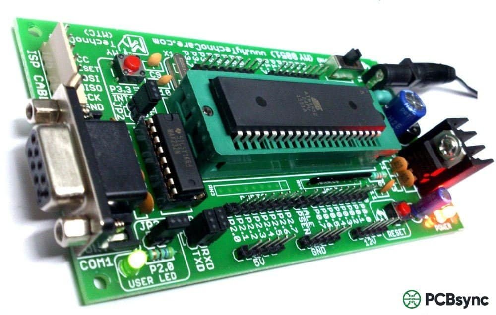
What Is an IC Programmer?
An IC programmer (also called a device programmer, chip programmer, or PROM writer) is specialized hardware that writes data into programmable ICs. It generates the precise voltage sequences and timing required by each device type, handles communication protocols, and verifies successful programming.
How IC Programmers Work
The basic operation follows a consistent pattern:
Connection: The IC connects to the programmer via a socket or in-circuit interface
Identification: The programmer reads device ID information to confirm compatibility
Preparation: Memory is erased (for flash-based devices) or verified blank
Programming: Data transfers to the IC according to manufacturer specifications
Verification: The programmer reads back and compares against the source file
Modern programmers handle this automatically, but understanding the process helps troubleshoot when things go wrong.
Types of IC Programmers
Programmers range from budget-friendly development tools to high-volume automated systems. Selecting the right type depends on your production volume, device support requirements, and budget.
Programmer Type
Best For
Throughput
Typical Cost Range
Development/Desktop
R&D, prototyping, low volume
10-100 units/day
$200 – $2,000
Universal Programmer
Mixed device support, medium volume
100-500 units/day
$1,000 – $5,000
Gang Programmer
Production, single device type
500-2,000 units/day
$3,000 – $15,000
Automated Handler
High-volume manufacturing
2,000-10,000+ units/day
$30,000 – $200,000+
ISP/In-System
On-board programming, field updates
Varies
$50 – $1,000
Development Programmers
Desktop units like the Xeltek SuperPro 610P or Dataman 48 series support thousands of devices and work well for engineering labs and repair shops. They’re compact, USB-powered, and come with ZIF sockets for easy device insertion.
Universal Programmers
These workhorses balance device support with production capability. The SuperPro 6100N, for example, supports over 115,000 devices with 144 pin drivers and can operate standalone without a PC—useful for production environments where you want to minimize computer dependencies.
Gang Programmers
When you’re programming thousands of identical devices, gang programmers with 4, 8, or 16 sockets dramatically increase throughput. They program multiple ICs simultaneously in a round-robin fashion, maximizing efficiency.
Automated Programming Systems
For serious production volumes, automated handlers integrate robotic pick-and-place with programming sockets. Systems like the Xeltek SuperBOT series can program over 2,500 units per hour while handling tape-and-reel or tray input/output. They’re essential for manufacturing environments where labor costs and quality consistency matter.
IC Programming Methods and Interfaces
The method you use to program an IC depends on whether the device is already mounted on a PCB and what interfaces are available.
Offline Programming (Pre-Assembly)
Devices are programmed before board assembly using socket-based programmers. This approach offers:
High throughput: Dedicated equipment optimized for speed
Quality control: Programmed devices can be tested before assembly
Inventory flexibility: Stock blank devices and program as needed
The main drawback is handling—ICs must be physically inserted into sockets, which can damage leads if done carelessly.
In-System Programming (ISP)
ISP allows programming devices already soldered to the PCB through dedicated test points or headers. This method is increasingly popular because:
Reduced handling: No socket insertion/removal cycles
Field updates: Enables firmware updates on deployed products
Lower inventory: No need to maintain pre-programmed stock
ISP requires proper PCB design with accessible programming interfaces and may be slower than offline methods.
Common Programming Interfaces
Interface
Pins Required
Typical Use
Speed
JTAG
4-5
MCUs, FPGAs, debugging
Fast
SWD
2
ARM Cortex MCUs
Fast
SPI
4
Flash memory, some MCUs
Medium
I2C
2
EEPROMs, small memory
Slow
UART
2
Bootloader-based programming
Variable
Parallel
8+
Legacy memory devices
Fast
JTAG (Joint Test Action Group) deserves special mention because it’s not just a programming interface—it’s also a powerful debugging tool. When you’re stuck on a firmware bug at 2 AM, JTAG’s ability to halt execution, inspect registers, and single-step through code becomes invaluable.
Programming Languages for IC Development
The language you use depends on the IC type and application requirements.
For Microcontrollers
C and C++ dominate embedded development. They provide low-level hardware access with enough abstraction for maintainable code. Most MCU vendors provide C compilers and development environments (Keil MDK, MPLAB X, STM32CubeIDE).
Assembly still appears in performance-critical code sections, interrupt handlers, and bootloaders where you need cycle-accurate timing.
For FPGAs and CPLDs
VHDL and Verilog are hardware description languages that define digital logic structure rather than sequential instructions. VHDL’s strict typing suits safety-critical applications (aerospace, medical), while Verilog’s C-like syntax appeals to engineers with software backgrounds.
SystemVerilog extends Verilog with advanced verification features, making it popular for complex ASIC and FPGA designs.
For Automation and Testing
Python increasingly appears in production environments for automation scripts, test frameworks, and programming station control. Its extensive libraries and quick development cycle make it ideal for manufacturing test systems.
File Formats for IC Programming
Programming files come in several standard formats. Understanding these helps when troubleshooting or converting between tools.
Format
Extension
Description
Use Case
Intel HEX
.hex
ASCII text with address info
MCUs, most universal
Motorola S-Record
.s19, .srec
Similar to Intel HEX
Automotive, Freescale/NXP devices
Binary
.bin
Raw data, no address info
Flash devices, requires start address
ELF
.elf
Includes debug symbols
Development, debugging
JEDEC
.jed
PLD fuse map format
CPLDs, PALs
Bitstream
.bit, .rbf
FPGA configuration
Xilinx, Intel FPGAs
Intel HEX files are the most universal—nearly every programmer accepts them. The format encodes data as ASCII hexadecimal with record type, address, and checksum information, making it human-readable (sort of) and resilient to transmission errors.
Step-by-Step IC Programming Process
Here’s the practical workflow I follow for production IC programming:
1. Preparation
Verify firmware version and checksum against release documentation
Handle programmed devices carefully—static discharge can corrupt flash
Store in antistatic packaging until assembly
Common Programming Errors and Solutions
Error
Likely Cause
Solution
Device not found
Wrong socket, bad contact, incorrect device selection
Verify orientation, clean contacts, check device ID
Verification failed
Insufficient programming voltage, timing issues
Increase Vcc slightly, reduce programming speed
Blank check failed
Device not fully erased, defective chip
Retry erase, try different chip
Communication timeout
Poor connection, interference
Check cables, reduce cable length, verify power supply
Choosing the Right IC Programmer
Selecting a programmer involves balancing several factors:
Device Support
This is often the deciding factor. Check the manufacturer’s device list carefully—not just for your current project, but for foreseeable future needs. Major vendors like Xeltek, Elnec (also sold as Dataman and BK Precision), and Data I/O maintain extensive libraries with regular updates.
Medium volume (100-1,000 units/week): Gang programmer or multiple desktop units
High volume (>1,000 units/week): Automated handler system
Total Cost of Ownership
Budget programmers save money upfront but may cost more long-term through slower speeds, limited device support, and poor reliability. Calculate your cost per programmed device including labor, and the math often favors investing in better equipment.
Support and Updates
Algorithm updates are essential as IC manufacturers release new devices and silicon revisions. Some vendors provide free lifetime updates; others charge annual fees. Factor this into your decision.
IC Programming in Different Industries
Automotive Electronics
Automotive applications demand exceptional reliability and traceability. Programming systems must support:
AEC-Q100 qualified devices
Secure key provisioning for immobilizers and ECUs
Complete data logging for quality audits
High-temperature operation for in-vehicle applications
Modern vehicles contain 50-100+ microcontrollers, making programming a significant manufacturing consideration.
Consumer Electronics
Consumer markets prioritize speed and cost. High-volume programming with automated handlers is standard, and cycle time optimization directly impacts profitability.
Industrial and IoT
Industrial applications often require field-programmable devices for firmware updates and configuration changes. In-system programming capability becomes essential, and security (preventing unauthorized firmware modification) is increasingly important.
Medical Devices
Medical electronics face strict regulatory requirements. Programming stations must maintain detailed records, and the programming process itself may require validation as part of the device’s regulatory submission.
Best Practices for Production IC Programming
After setting up dozens of programming stations, here are the practices that consistently deliver results:
Design for Programming
Include accessible ISP headers on your PCB layout. Route programming signals carefully to maintain signal integrity. Consider programming voltage requirements when designing power supplies.
Validate Everything
Run sample batches through your complete process before production. Verify programmed devices function correctly in the final application—programming success doesn’t guarantee correct firmware.
Maintain Your Equipment
Socket pins wear out. Clean sockets regularly (isopropyl alcohol and a brush work well), replace worn pins promptly, and calibrate programmers according to manufacturer schedules.
Document Thoroughly
Record firmware versions, checksum values, and programming parameters. When a customer reports an issue two years later, you’ll be glad you can trace exactly what was programmed.
Protect Firmware Security
Use code protection features to prevent unauthorized reading. For sensitive applications, implement secure provisioning with encrypted firmware and device-unique keys.
Useful Resources for IC Programming
Manufacturer Device Databases
Xeltek Device Search: xeltek.com/device-search — Largest database with 115,000+ supported devices
Elnec Device List: elnec.com — Comprehensive European manufacturer
Data I/O: dataio.com — Industry pioneer with extensive automation solutions
Programming Software Tools
STM32CubeProgrammer: Free tool for STM32 devices, supports JTAG, SWD, UART, USB
MPLAB X IPE: Microchip’s production programming environment
OpenOCD: Open-source debugger/programmer supporting many devices
Programming time varies dramatically by device type and size. A small 8-bit MCU with 8KB flash programs in under a second. A 256GB eMMC device might take 30 minutes or more. For production planning, always test actual programming times with your specific firmware and equipment.
Can I program any IC with a universal programmer?
Universal programmers support broad device ranges, but not every IC is programmable, and not every programmable IC uses standard interfaces. Always verify device support before purchasing a programmer. Some devices (particularly newer or specialized ICs) may require manufacturer-specific programming tools.
What’s the difference between programming and debugging?
Programming writes firmware to a device—it’s a one-way data transfer. Debugging involves two-way communication: halting execution, reading memory and registers, setting breakpoints, and controlling program flow. Many interfaces (JTAG, SWD) support both, but they’re distinct operations.
How do I protect my firmware from being copied?
Most MCUs include code protection features that prevent reading the flash memory contents. Enable these features during programming. For higher security, implement encrypted firmware with secure boot—the bootloader decrypts and verifies firmware before execution. Hardware security modules (HSMs) and secure enclaves provide additional protection for critical applications.
Is it possible to recover a “bricked” device?
Often, yes. If the device’s programming interface remains accessible, you can usually erase and reprogram. Problems arise when:
Fuse bits disable the programming interface
Bootloader code is corrupted
Security features lock the device permanently
Prevention is easier than cure—always verify programming parameters before writing fuse/option bytes.
Conclusion
IC programming bridges the gap between hardware capability and functional electronics. Whether you’re programming a single prototype microcontroller or managing a production line churning out thousands of devices daily, understanding this process is fundamental to modern electronics manufacturing.
The key takeaways:
Match your programmer to your needs: Consider device support, volume requirements, and total cost of ownership
Choose the right programming method: Offline for volume, in-system for flexibility
Design for success: Include proper programming interfaces in your PCB designs
Validate and document: Test thoroughly and maintain traceability records
The IC programming industry continues evolving with larger memories, more complex security requirements, and increased automation. Staying current with these developments helps you deliver better products more efficiently.
Advanced Topics in IC Programming
Secure Provisioning and Encryption
As connected devices proliferate, security has become a critical programming consideration. Modern secure provisioning involves:
Root of Trust Establishment: Programming cryptographic keys that form the foundation of device security
Secure Boot Implementation: Loading bootloaders that verify firmware authenticity before execution
Device Attestation: Enabling devices to prove their identity to cloud services and backend systems
Anti-Cloning Protection: Preventing unauthorized copying of firmware and device credentials
Automotive and IoT applications increasingly require Hardware Security Modules (HSMs) integration during the programming process. The programmer must communicate with secure elements, manage certificate chains, and handle encrypted firmware payloads—all while maintaining production throughput.
Programming Automation and Industry 4.0
Manufacturing trends toward Industry 4.0 principles are transforming IC programming operations:
MES Integration: Programming stations communicate with Manufacturing Execution Systems for real-time production tracking
Automated Lot Management: Systems automatically load correct firmware versions based on work orders
Statistical Process Control: Programming data feeds quality systems for trend analysis and early problem detection
Traceability: Every programmed device links to its firmware version, programming parameters, and production batch
Leading programming equipment manufacturers now offer API access and standard communication protocols (OPC-UA, MQTT) to facilitate this integration.
Handling Large Memory Devices
Programming modern storage devices presents unique challenges. An eMMC or UFS device with 256GB capacity takes considerable time to program, even with optimized algorithms. Strategies for handling large devices include:
Data Compression: Compressing firmware before transfer and decompressing on-device
Sparse Image Programming: Only programming sectors that contain actual data, skipping empty regions
Parallel Programming: Using gang programmers with multiple simultaneous device channels
Pre-programming Staging: Programming storage devices well ahead of assembly to prevent production bottlenecks
Future Trends in IC Programming
Several developments are shaping the future of this field:
AI-Assisted Programming: Machine learning algorithms are beginning to appear in programming systems, optimizing parameters automatically and predicting potential failures before they occur.
Over-the-Air Updates: While not replacing initial programming, OTA update capability affects how production programming is approached—devices need secure bootloaders and update mechanisms from day one.
Chiplet Architectures: As semiconductor designs move toward chiplet-based approaches with multiple dies in a package, programming strategies must adapt to address multiple programmable elements within a single component.
Security Regulations: Increasing government requirements for IoT security (EU Cyber Resilience Act, NIST guidelines) are making secure programming mandatory rather than optional.
Troubleshooting Guide for IC Programming Issues
Even experienced engineers encounter programming problems. Here’s a systematic approach to diagnosing and resolving common issues:
Connection and Communication Problems
Symptom: “Device not detected” or “Cannot connect to target”
Inquire: Call 0086-755-23203480, or reach out via the form below/your sales contact to discuss our design, manufacturing, and assembly capabilities.
Quote: Email your PCB files to Sales@pcbsync.com (Preferred for large files) or submit online. We will contact you promptly. Please ensure your email is correct.
Notes: For PCB fabrication, we require PCB design file in Gerber RS-274X format (most preferred), *.PCB/DDB (Protel, inform your program version) format or *.BRD (Eagle) format. For PCB assembly, we require PCB design file in above mentioned format, drilling file and BOM. Click to download BOM template To avoid file missing, please include all files into one folder and compress it into .zip or .rar format.


