Inquire: Call 0086-755-23203480, or reach out via the form below/your sales contact to discuss our design, manufacturing, and assembly capabilities.
Quote: Email your PCB files to Sales@pcbsync.com (Preferred for large files) or submit online. We will contact you promptly. Please ensure your email is correct.
Notes: For PCB fabrication, we require PCB design file in Gerber RS-274X format (most preferred), *.PCB/DDB (Protel, inform your program version) format or *.BRD (Eagle) format. For PCB assembly, we require PCB design file in above mentioned format, drilling file and BOM. Click to download BOM template To avoid file missing, please include all files into one folder and compress it into .zip or .rar format.
I2C on Raspberry Pi: Connect Multiple Sensors (Complete Guide)
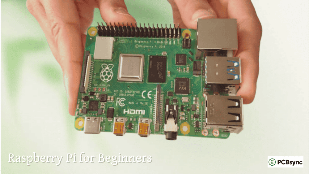
Working with embedded systems for over a decade, I’ve connected thousands of sensors to microcontrollers. The i2c raspberry pi combination remains my go-to recommendation for anyone building multi-sensor projects. Why? Because I2C lets you connect dozens of devices using just two wires, dramatically simplifying both your PCB layout and wiring harness.
This guide covers everything you need to know about raspberry pi i2c python programming, from enabling the interface to connecting multiple sensors on a single bus. Whether you’re building a weather station, robotics project, or industrial monitoring system, mastering I2C opens doors to hundreds of compatible sensors and modules.
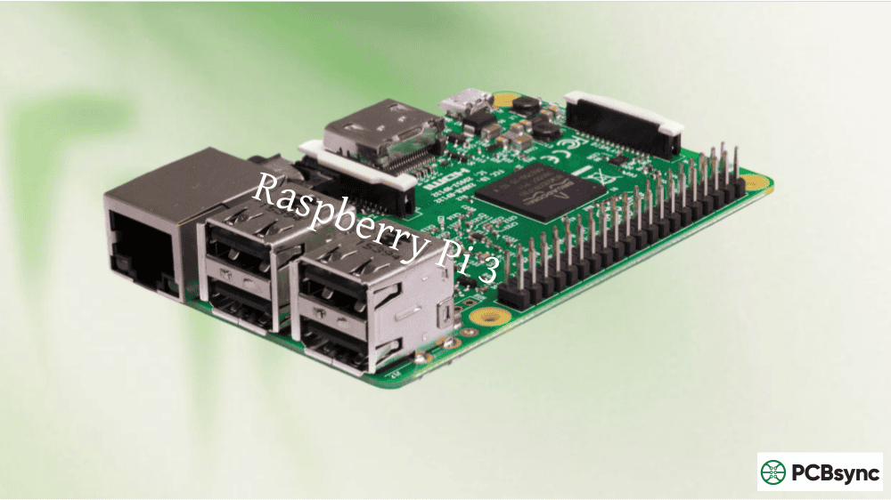
I2C (Inter-Integrated Circuit), pronounced “I-squared-C” or “I-two-C,” is a synchronous serial communication protocol developed by Philips Semiconductor in the 1980s. It uses just two bidirectional lines to communicate between a master device (your Raspberry Pi) and multiple slave devices (sensors, displays, EEPROMs).
The two lines are SDA (Serial Data) for transferring data bidirectionally, and SCL (Serial Clock) for synchronizing communication. The master device controls the clock, while slaves respond when addressed.
How I2C Addressing Works
Every I2C device has a unique 7-bit address, allowing up to 127 devices on a single bus (address 0x00 is reserved for general calls). Manufacturers assign default addresses, though many devices offer configurable address pins for situations where you need multiple identical sensors.
Address Range
Typical Usage
0x00
General call (reserved)
0x01-0x07
Reserved addresses
0x08-0x77
User device addresses
0x78-0x7F
Reserved for 10-bit addressing
When you power up an I2C device, it listens for its specific address on the bus. Only when the master sends that address does the slave respond. This elegant design means adding sensors requires no additional GPIO pins beyond the shared SDA and SCL lines.
I2C Pins on Raspberry Pi
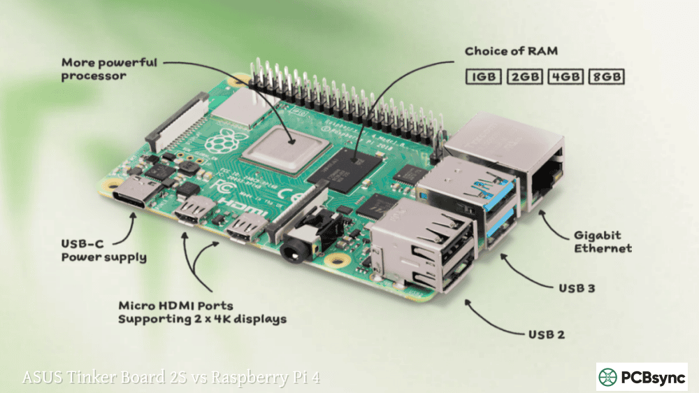
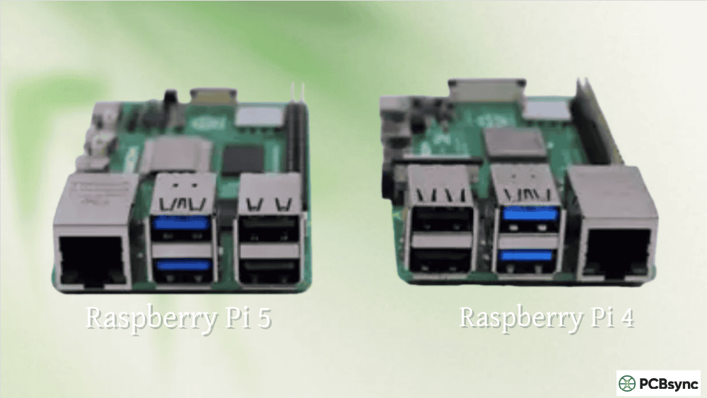
The Raspberry Pi exposes I2C on specific GPIO pins. Understanding which pins to use prevents wiring mistakes that could damage your hardware.
Pi Model
I2C Bus
SDA Pin
SCL Pin
Notes
Pi 1 Model A/B (26-pin)
I2C-0
GPIO0 (Pin 3)
GPIO1 (Pin 5)
Older models
Pi 1 B+, Pi 2, 3, 4, 5
I2C-1
GPIO2 (Pin 3)
GPIO3 (Pin 5)
Standard bus
All 40-pin models
I2C-0
GPIO0 (Pin 27)
GPIO1 (Pin 28)
Reserved for HAT EEPROM
The primary user-accessible I2C bus on modern Raspberry Pi boards is I2C-1, available on physical pins 3 (SDA) and 5 (SCL). These pins have internal 1.8kΩ pull-up resistors to 3.3V, so external pull-ups are usually unnecessary for short cable runs.
I2C-0 exists on pins 27 and 28 but is reserved for communicating with HAT (Hardware Attached on Top) EEPROMs. Avoid using I2C-0 unless you specifically need it and understand the implications.
Enabling I2C on Raspberry Pi
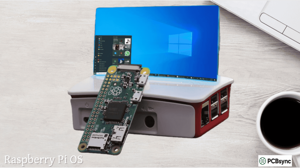
The I2C interface is disabled by default on Raspberry Pi OS. You must enable it before any I2C communication will work.
Method 1: Using raspi-config
The simplest approach uses the built-in configuration tool:
sudo raspi-config
Navigate to Interface Options, select I2C, and choose Yes to enable. Reboot when prompted.
Method 2: Using the Desktop GUI
On Raspberry Pi OS with desktop, click the start menu, select Preferences, then Raspberry Pi Configuration. In the Interfaces tab, enable I2C and reboot.
Method 3: Manual Configuration
For headless setups or automation scripts, edit the boot configuration directly:
sudo nano /boot/config.txt
Add or uncomment this line:
dtparam=i2c_arm=on
Then enable the kernel module by editing:
sudo nano /etc/modules
Add this line if not present:
i2c-dev
Reboot to apply changes:
sudo reboot
Installing I2C Tools and Python Libraries
After enabling I2C, install the necessary software packages:
sudo apt update
sudo apt install -y i2c-tools python3-smbus
For Python 3 development with newer libraries:
pip3 install smbus2
The smbus2 library is a pure Python implementation that provides additional features over the standard smbus module while maintaining backward compatibility.
Detecting I2C Devices
Before writing code, verify your hardware connections using the i2cdetect utility. This scans the I2C bus and reports addresses of connected devices.
sudo i2cdetect -y 1
The output displays a grid showing detected device addresses:
0 1 2 3 4 5 6 7 8 9 a b c d e f
00: — — — — — — — — — — — — —
10: — — — — — — — — — — — — — — — —
20: — — — — — — — — — — — — — — — —
30: — — — — — — — — — — — — — — — —
40: — — — — — — — — 48 — — — — — — —
50: — — — — — — — — — — — — — — — —
60: — — — — — — — — 68 — — — — — — —
70: — — — — — — — 77
This example shows three devices detected at addresses 0x48, 0x68, and 0x77. If you see dashes everywhere, check your wiring and ensure I2C is properly enabled.
Raspberry Pi I2C Python Programming Basics
The SMBus library provides the foundation for i2c raspberry pi communication in Python. Here’s how the core functions work:
Creating an SMBus Connection
import smbus2
# For Pi 1 Model A/B use bus 0, all others use bus 1
bus = smbus2.SMBus(1)
Common SMBus Functions
Function
Description
Parameters
read_byte(addr)
Read single byte without register
Device address
read_byte_data(addr, reg)
Read byte from specific register
Address, register
read_word_data(addr, reg)
Read 16-bit word from register
Address, register
read_i2c_block_data(addr, reg, length)
Read multiple bytes
Address, register, count
write_byte(addr, val)
Write single byte
Address, value
write_byte_data(addr, reg, val)
Write byte to register
Address, register, value
write_i2c_block_data(addr, reg, data)
Write multiple bytes
Address, register, data list
Basic Read/Write Example
import smbus2
import time
bus = smbus2.SMBus(1)
device_address = 0x48 # Example: TMP102 temperature sensor
temp_register = 0x00
# Read two bytes from the temperature register
data = bus.read_i2c_block_data(device_address, temp_register, 2)
# Convert raw bytes to temperature (sensor-specific)
Always close the bus connection when finished, or use context managers for automatic cleanup:
with smbus2.SMBus(1) as bus:
data = bus.read_byte_data(0x48, 0x00)
Connecting Multiple I2C Sensors
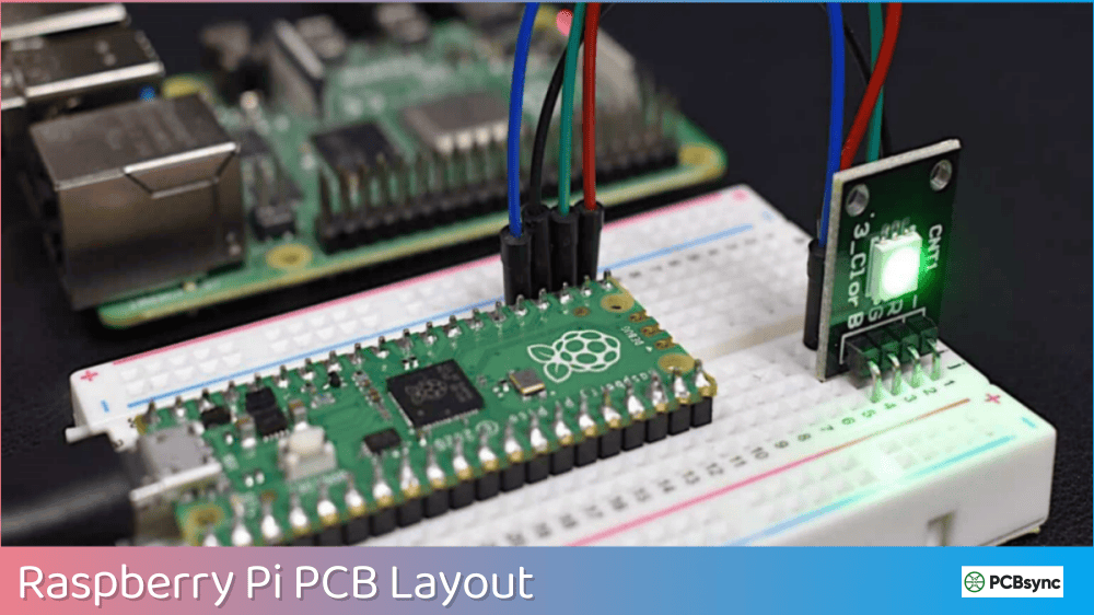
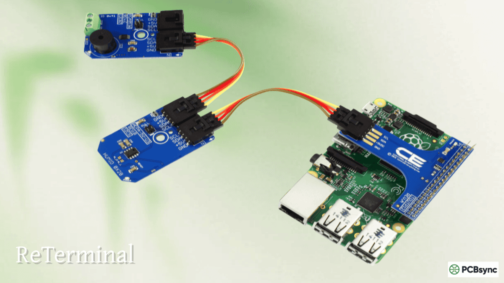
The real power of I2C emerges when connecting multiple sensors. Each device simply shares the same SDA and SCL lines while responding only to its unique address.
Wiring Multiple Sensors
Connect all sensor SDA pins together and to GPIO2 (pin 3). Connect all sensor SCL pins together and to GPIO3 (pin 5). Each sensor needs its own power and ground connections, though these can share the same power rail.
For runs longer than 30cm, consider adding external pull-up resistors (typically 4.7kΩ to 10kΩ) to improve signal integrity.
Multi-Sensor Python Example
import smbus2
import time
bus = smbus2.SMBus(1)
# Sensor addresses
BME280_ADDR = 0x76 # Environmental sensor
MPU6050_ADDR = 0x68 # Accelerometer/Gyroscope
BH1750_ADDR = 0x23 # Light sensor
def read_bme280_temp():
# Simplified – actual implementation needs calibration
data = bus.read_i2c_block_data(BME280_ADDR, 0xFA, 3)
Address conflicts occur when two devices share the same default address. Several solutions exist:
Using Address Selection Pins
Many sensors include address pins (often labeled A0, A1, A2) that modify the device address. Connecting these pins to VCC or GND changes specific address bits.
A2
A1
A0
Address
GND
GND
GND
0x20
GND
GND
VCC
0x21
GND
VCC
GND
0x22
VCC
VCC
VCC
0x27
Using an I2C Multiplexer
When address pins aren’t available or you need many identical sensors, I2C multiplexers like the TCA9548A solve the problem elegantly. This chip provides eight separate I2C buses, each accessible by writing a channel selection byte.
import smbus2
bus = smbus2.SMBus(1)
TCA9548A_ADDR = 0x70
def select_channel(channel):
“””Select TCA9548A channel (0-7)”””
bus.write_byte(TCA9548A_ADDR, 1 << channel)
# Read from sensor on channel 0
select_channel(0)
data_sensor1 = bus.read_byte_data(0x48, 0x00)
# Read from identical sensor on channel 1
select_channel(1)
data_sensor2 = bus.read_byte_data(0x48, 0x00)
Creating Additional I2C Buses
The Raspberry Pi can bit-bang additional I2C buses on any GPIO pins using device tree overlays. Add these lines to /boot/config.txt:
After rebooting, access the new bus with SMBus(3).
Popular I2C Sensors and Their Addresses
Sensor
Function
Default Address
Library
BME280
Temp/Humidity/Pressure
0x76 or 0x77
adafruit-circuitpython-bme280
BMP280
Temp/Pressure
0x76 or 0x77
adafruit-circuitpython-bmp280
MPU6050
Accelerometer/Gyro
0x68 or 0x69
mpu6050-raspberrypi
SHT31
Temp/Humidity
0x44 or 0x45
adafruit-circuitpython-sht31d
ADS1115
16-bit ADC
0x48-0x4B
adafruit-circuitpython-ads1x15
PCA9685
PWM Driver
0x40-0x7F
adafruit-circuitpython-pca9685
OLED SSD1306
Display
0x3C or 0x3D
adafruit-circuitpython-ssd1306
MCP23017
GPIO Expander
0x20-0x27
adafruit-circuitpython-mcp230xx
Troubleshooting I2C Problems
After years of debugging I2C issues on production boards, these are the most common problems and solutions:
No Devices Detected
First, verify I2C is enabled with ls /dev/i2c*. If nothing appears, revisit the enabling steps. Check physical connections with a multimeter, confirming SDA and SCL have continuity to the correct GPIO pins.
Intermittent Communication Failures
Usually indicates signal integrity issues. Add 4.7kΩ pull-up resistors on both SDA and SCL lines. Shorten cable lengths or reduce I2C clock speed:
# Add to /boot/config.txt
dtparam=i2c_arm_baudrate=50000
“Remote I/O Error” in Python
This error typically means the device isn’t responding at the expected address. Verify the address with i2cdetect, check power supply voltage, and ensure the sensor isn’t in sleep mode.
Device Shows as “UU” in i2cdetect
The “UU” indication means a kernel driver has claimed that address. This isn’t necessarily a problem, but you may need to unload the driver to access the device directly from Python.
Useful Resources and Downloads
Resource
URL
Description
SMBus2 Documentation
pypi.org/project/smbus2
Python library reference
Raspberry Pi Pinout
pinout.xyz/pinout/i2c
Interactive pin diagram
I2C Address Database
i2cdevices.org
Searchable sensor addresses
Adafruit CircuitPython
circuitpython.org
Sensor libraries
SparkFun I2C Tutorial
learn.sparkfun.com
Protocol deep-dive
Linux I2C Tools
kernel.org/doc/Documentation/i2c
Kernel documentation
Frequently Asked Questions
How many I2C devices can I connect to a Raspberry Pi?
Theoretically, up to 127 devices can share a single I2C bus since addresses are 7 bits. Practically, electrical limitations (bus capacitance, signal degradation) restrict this to around 20-30 devices for reliable operation. Using I2C multiplexers or additional bit-banged buses extends this considerably.
What is the maximum cable length for I2C on Raspberry Pi?
Standard I2C operates reliably up to about 1 meter with the default 100kHz clock. Reducing clock speed to 10kHz extends range to several meters. For longer distances, consider I2C bus extenders or switching to RS-485 communication. The internal 1.8kΩ pull-ups on the Pi are relatively weak, so adding external 4.7kΩ pull-ups improves reliability on longer runs.
Can I use 5V I2C sensors with Raspberry Pi?
The Raspberry Pi GPIO pins are 3.3V only and connecting 5V signals directly will damage the board. Use a bidirectional logic level converter between 5V sensors and the Pi. Many modern sensors operate at 3.3V natively, avoiding this issue entirely.
What is the difference between smbus and smbus2 libraries?
The original smbus library wraps the C i2c-dev interface but lacks some features and proper error handling. smbus2 is a pure Python drop-in replacement with better documentation, context manager support, and additional I2C message types. For new projects, always use smbus2.
Why does i2cdetect show different addresses than expected?
I2C addresses can be expressed as 7-bit or 8-bit values. Some datasheets show 8-bit addresses (including the read/write bit), which appear twice as large. Divide the datasheet address by 2 to get the 7-bit address used by Linux and Python. For example, a datasheet showing 0x90 means the 7-bit address is 0x48.
Advanced I2C Configuration Options
The Raspberry Pi offers several configuration parameters to optimize I2C performance for specific applications.
Adjusting I2C Bus Speed
The default I2C clock frequency is 100kHz (standard mode). Some sensors support faster speeds:
Through years of designing I2C-based products, certain practices consistently improve reliability. Always include bypass capacitors (100nF ceramic) close to each sensor’s power pins. Use twisted pair or shielded cable for runs over 30cm. Implement retry logic in your Python code for occasional communication failures.
For production systems, consider implementing a watchdog that resets the I2C bus if communication stalls. The Raspberry Pi’s I2C hardware can occasionally lock up, requiring a bus reset or reboot to recover.
The raspberry pi i2c python ecosystem continues expanding with new sensors and libraries released regularly. The fundamentals covered here apply regardless of which specific sensors you choose. Master these concepts, and you’ll connect any I2C device confidently.
Start simple with one or two sensors, verify communication works reliably, then expand your system incrementally. This methodical approach catches wiring errors and address conflicts early when they’re easy to diagnose.
Inquire: Call 0086-755-23203480, or reach out via the form below/your sales contact to discuss our design, manufacturing, and assembly capabilities.
Quote: Email your PCB files to Sales@pcbsync.com (Preferred for large files) or submit online. We will contact you promptly. Please ensure your email is correct.
Notes: For PCB fabrication, we require PCB design file in Gerber RS-274X format (most preferred), *.PCB/DDB (Protel, inform your program version) format or *.BRD (Eagle) format. For PCB assembly, we require PCB design file in above mentioned format, drilling file and BOM. Click to download BOM template To avoid file missing, please include all files into one folder and compress it into .zip or .rar format.


