Inquire: Call 0086-755-23203480, or reach out via the form below/your sales contact to discuss our design, manufacturing, and assembly capabilities.
Quote: Email your PCB files to Sales@pcbsync.com (Preferred for large files) or submit online. We will contact you promptly. Please ensure your email is correct.
Notes: For PCB fabrication, we require PCB design file in Gerber RS-274X format (most preferred), *.PCB/DDB (Protel, inform your program version) format or *.BRD (Eagle) format. For PCB assembly, we require PCB design file in above mentioned format, drilling file and BOM. Click to download BOM template To avoid file missing, please include all files into one folder and compress it into .zip or .rar format.
High TG PCB Guide: Glass Transition Temperature, Materials & When to Use Them
If you’ve been designing PCBs for any length of time, you’ve probably run into situations where standard FR4 just doesn’t cut it. Maybe you’re working on automotive electronics that sit near the engine, or perhaps you’re dealing with high-power LED drivers that generate significant heat. This is where high TG PCBs come into play, and understanding when and why to use them can save you from costly field failures down the road.
I’ve seen too many projects where engineers either over-spec their boards (wasting money on TG180 when TG150 would suffice) or under-spec them (using standard FR4 in applications that clearly need better thermal performance). This guide will help you make informed decisions about TG selection based on real-world requirements rather than guesswork.
Glass transition temperature is the point at which your PCB’s base material transforms from a rigid, glassy state to a softer, rubbery condition. Think of it like butter sitting on a warm counter—it doesn’t melt instantly, but gradually softens as temperature rises. Your PCB substrate behaves similarly.
The critical thing to understand is that TG isn’t the maximum temperature your board can handle. It’s the threshold where mechanical and electrical properties start degrading. Once you exceed TG, the coefficient of thermal expansion (CTE) increases dramatically, especially in the Z-axis. This puts stress on plated through-holes, vias, and solder joints—exactly the places where reliability matters most.
Standard FR4 typically has a TG between 130°C and 140°C. For many consumer electronics that operate in climate-controlled environments, this works fine. But when operating temperatures climb—or when you’re putting boards through multiple reflow cycles with lead-free solder—standard materials show their limitations quickly.
🔧 PCBSync High TG PCB Engineering Tool
Professional Design Assistant for High Temperature Glass Transition PCBs
🎯 Find Your Ideal TG Level
📋 Recommended TG Level:
📈 TG Level Comparison Chart
TG Level
Temp Range
Cost Factor
Best For
Lead-Free
Standard (Tg130-140)
≤85°C
1.0x
Consumer electronics, Low-cost
⚠️ Limited
Medium (Tg150-170)
85-125°C
1.1-1.2x
Automotive, Industrial, LED
✅ Good
High (Tg170-180)
125-150°C
1.2-1.4x
Server, Telecom, Multi-layer
✅ Excellent
Very High (Tg180-210)
150-175°C
1.5-1.8x
Aerospace, Medical, Power
✅ Excellent
Ultra High (Tg250-300+)
>175°C
2.5-4.0x
Extreme environments, Defense
✅ Superior
🧪 High TG PCB Materials Database
FR-4 High TGTg 170-180°C
Td: 340°C | Dk: 4.2-4.5 | Df: 0.019-0.025
CTE (Z): 45-55 ppm/°C | T288: >15 min
Common Brands: Shengyi S1000-2, ITEQ IT-180A, Isola 370HR
Best For: Lead-free assembly, multi-layer boards, HDI
ITEQ IT-180ATg 180°C
Td: 340°C | Dk: 4.4 | Df: 0.019
CTE (Z): 50 ppm/°C | T288: >20 min
Features: Low CTE, excellent thermal reliability
Best For: Automotive, industrial, lead-free SMT
Shengyi S1000-2MTg 150°C
Td: 320°C | Dk: 4.3 | Df: 0.018
CTE (Z): 55 ppm/°C | T288: >10 min
Features: Cost-effective, good processability
Best For: Mid-range applications, LED lighting
Isola 370HRTg 180°C
Td: 340°C | Dk: 4.04 | Df: 0.021
CTE (Z): 45 ppm/°C | T288: >60 min
Features: Superior thermal reliability, low CTE
Best For: High-reliability, aerospace, defense
Polyimide (PI)Tg 250-280°C
Td: 400°C+ | Dk: 3.4-3.5 | Df: 0.010-0.015
CTE (Z): 30-40 ppm/°C | T288: >60 min
Features: Extreme temperature resistance, flexible
Best For: Aerospace, downhole drilling, extreme environments
BT Epoxy (Bismaleimide)Tg 210-250°C
Td: 380°C | Dk: 3.8-4.0 | Df: 0.012-0.018
CTE (Z): 35-45 ppm/°C | T288: >30 min
Features: IC substrate, fine line capability
Best For: BGA substrates, high-frequency, aerospace
Panasonic Megtron 6Tg 185°C
Td: 400°C | Dk: 3.4 | Df: 0.002
CTE (Z): 38 ppm/°C | T288: >30 min
Features: Ultra-low loss, high-speed signal integrity
Best For: High-speed digital, RF/microwave, 5G
TUC TU-872Tg 175°C
Td: 350°C | Dk: 4.4 | Df: 0.013
CTE (Z): 50 ppm/°C | T288: >20 min
Features: Halogen-free, RoHS compliant
Best For: Consumer, automotive, green electronics
📖 Material Properties Key:
Tg = Glass Transition TempTd = Decomposition TempDk = Dielectric ConstantDf = Dissipation FactorCTE = Coefficient of Thermal ExpansionT288 = Time to Delamination at 288°C
💰 High TG PCB Cost Estimator
Unit Price
$0.00
Total Cost
$0.00
TG Premium
+0%
💡 Cost Optimization Tips:
• Choose Medium TG (Tg170) instead of Very High TG if operating temp allows – saves 20-35%
• Panelize smaller boards to reduce per-unit costs
• Standard thickness (1.6mm) is most cost-effective
• Higher quantities significantly reduce unit price
• HASL finish is most economical for non-fine-pitch components
🌡️ Thermal Analysis Calculator
Est. Board Temp Rise
+0°C
Est. Max Board Temp
0°C
TG Margin
0°C
Safety Status
–
⚠️ Thermal Design Guidelines:
• Keep operating temp at least 20-30°C below TG for reliability
• PCB temperature can be 15-40°C above ambient depending on power density
• Copper planes act as heat spreaders – increase coverage near hot components
• Consider thermal vias under high-power components
• Lead-free reflow peak temperatures reach 245-260°C – ensure adequate TG margin
📚 High TG PCB Stack-Up Recommendations
2-Layer Stack-Up (High TG FR-4):
Top Copper (Signal/Power)
High TG FR-4 Core (1.5mm)
Bottom Copper (Signal/GND)
Total Thickness: ~1.6mm | Recommended Material: IT-180A, S1000-2 (Tg170+) Applications: Simple designs, single-sided SMT, low component density
Signal Layer Ground Plane Power Plane Core Prepreg Inner Signal
💡 High TG PCB Design Best Practices
🧪 Material Selection Guidelines
• Select TG at least 25-30°C above maximum operating temperature
• For lead-free assembly, use minimum Tg170°C materials
• Consider Td (decomposition temp) for reflow compatibility – aim for Td > 330°C
• Match CTE between core and prepreg to prevent warpage
• For high-frequency (>1GHz), prioritize low Dk/Df materials
• Verify UL 94 V-0 flammability rating for safety compliance
🌡️ Thermal Management Strategies
• Use thermal vias under high-power components (0.3mm diameter, 1mm pitch)
• Maximize copper pour on inner layers for heat spreading
• Consider 2oz copper for power layers in high-current designs
• Place temperature-sensitive components away from heat sources
• Use thermal relief patterns for hand-soldering pads
• Add heatsink mounting provisions for components >2W dissipation
🏭 Manufacturing Considerations
• High TG materials require slower drill speeds – specify in fab notes
• Allow extra time for lamination cycle with high TG materials
• Specify controlled impedance requirements clearly
• Request IPC Class 2 or 3 based on application reliability needs
• Include test coupons for high-reliability applications
• Specify maximum reflow cycles expected (typically 2-3 for double-sided SMT)
📐 Design for Manufacturability (DFM)
• Maintain 6/6 mil minimum trace/space for standard processes
• Use teardrop pads at via connections for reliability
• Avoid isolated copper pours that can trap moisture
• Balance copper distribution across layers to prevent warpage
• Include fiducials for automated assembly alignment
• Specify solder mask dam requirements between fine-pitch pads
🔧 Assembly & Soldering Tips
• Pre-bake boards at 125°C for 4 hours if stored >72 hours unsealed
• Lead-free reflow profile: peak 245-260°C, time above liquidus <90 seconds
• Allow boards to cool below 150°C before handling after reflow
• Use nitrogen atmosphere for reflow to reduce oxidation
• Verify paste-to-pad registration before reflow
• Consider step stencils for mixed component heights
🔬 Testing & Qualification
• Perform IST (Interconnect Stress Test) for high-reliability applications
• Thermal cycling test: -40°C to +125°C, 500-1000 cycles
• Measure insulation resistance after humidity exposure
• Cross-section analysis for via barrel integrity
• Solder joint inspection per IPC-A-610 standards
• Track warpage before and after assembly
📋 Quick Reference: TG Selection by Application
Consumer Electronics: Tg130-150°C
Automotive ECU: Tg170-180°C
Industrial Control: Tg150-170°C
Server/Telecom: Tg170-180°C
Aerospace/Defense: Tg180-280°C
Medical Implants: Tg180-250°C
Need expert assistance with your High TG PCB project?
Before diving into specific TG ratings, let’s clear up a common source of confusion: TG and Td (decomposition temperature) measure different things, and both matter for your design.
TG (Glass Transition Temperature): This is reversible. Heat a board above its TG, and it softens. Cool it down, and it returns to its rigid state. However, repeated thermal cycling above TG causes cumulative damage.
Td (Decomposition Temperature): This is irreversible. When you hit Td, the resin system chemically breaks down, releasing gases and losing mass. The board is permanently damaged. For most high TG FR4 materials, Td sits between 310°C and 355°C.
During lead-free reflow soldering, peak temperatures typically reach 240-260°C—well above the TG of standard FR4 but below Td. This is why material selection matters: you want a TG high enough to minimize expansion during soldering, and a Td high enough to survive the process without degradation.
Complete Guide to TG Material Types
Here’s where the practical knowledge comes in. Let me walk you through each TG classification, when to use it, and what trade-offs you’re making.
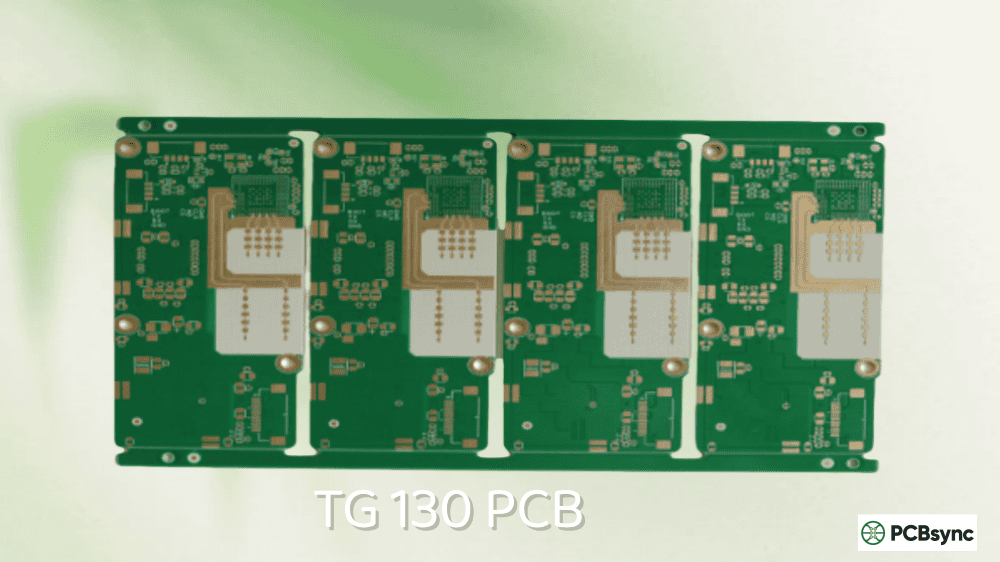
TG130: Standard FR4 for General Applications
TG130 represents the baseline for most PCB production. Materials like Shengyi S1141 or generic FR4 laminates fall into this category. Maximum safe operating temperature sits around 105-110°C.
Best suited for:
Consumer electronics (phones, tablets, laptops)
Low-power IoT devices
Prototyping and proof-of-concept boards
Cost-sensitive high-volume production
Limitations: Not recommended for lead-free assembly with multiple reflow cycles, HDI designs with stacked microvias, or any application where ambient temperatures regularly exceed 80°C.
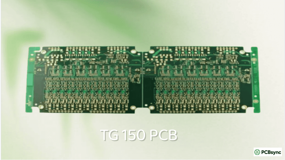
TG150: The Middle Ground
TG150 materials like Ventec VT-42S offer a step up from standard FR4 without the full premium of high TG options. Maximum operating temperature extends to approximately 125-130°C.
Best suited for:
LED lighting (moderate power)
Industrial control systems
Networking equipment
Single-pass lead-free soldering
Cost consideration: Typically 5-10% more expensive than TG130, making it a reasonable upgrade when you need extra thermal headroom without breaking the budget.
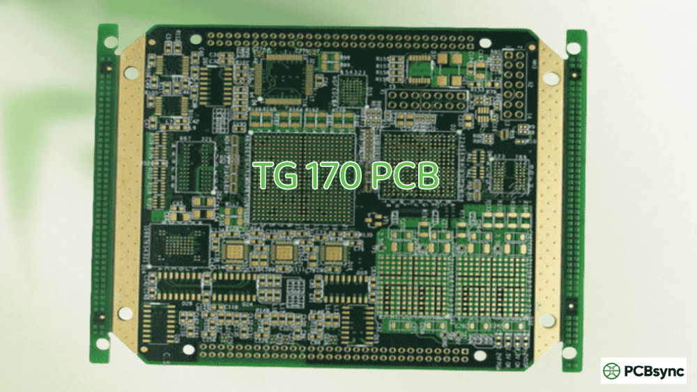
TG170: The Industry Workhorse
TG170 has become the de facto standard for anything requiring serious thermal performance. Materials like Shengyi S1000-2, ITEQ IT-180A, and Isola FR406 dominate this space. Maximum operating temperature reaches 145-150°C.
Best suited for:
Automotive electronics (non-underhood)
Server and datacenter equipment
Telecommunications infrastructure
Power supplies and motor controllers
Multilayer boards (8+ layers)
Multiple reflow cycle assemblies
Key advantage: TG170 materials typically offer Z-axis CTE values around 2.5-3.0%, compared to 3.5-4.0% for standard FR4. This translates directly to better via reliability during thermal cycling.
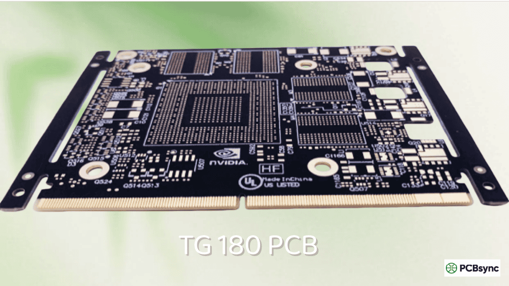
TG180: Premium Performance
TG180 represents the sweet spot for demanding applications. Materials like Isola 370HR, Ventec VT-47, and ITEQ IT-180ITC deliver enhanced performance with Td values typically exceeding 340°C. Maximum operating temperature approaches 155-160°C.
Performance data: In thermal stress testing, TG180 substrates can withstand 288°C for over 600 seconds, compared to approximately 300 seconds for TG140 materials. This margin matters significantly for complex assemblies requiring multiple thermal cycles.
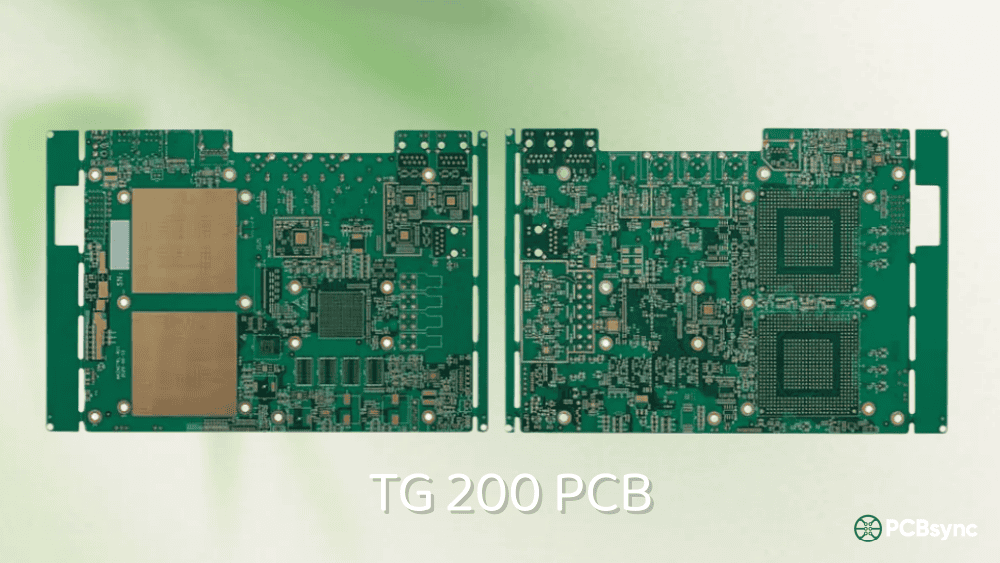
TG200: Specialized High-Performance
When you move beyond TG180, you’re entering specialized territory. TG200+ materials often use modified resin systems like BT epoxy or enhanced FR4 formulations. Materials include Shengyi S1860 (TG210) and Nelco N4000-13 (TG210). Maximum operating temperature reaches 170-180°C.
Best suited for:
High-speed digital circuits requiring low Dk/Df
IC substrate applications
Advanced packaging (BGA, flip-chip)
Aerospace avionics
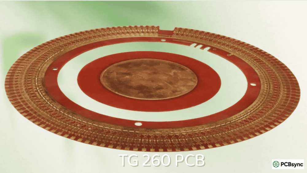
TG260: Polyimide and Extreme Applications
TG260 typically indicates polyimide-based materials rather than modified FR4. Shengyi SH260 and similar polyimide laminates offer exceptional thermal performance with Td values exceeding 400°C. Maximum operating temperature can reach 230-240°C.
Best suited for:
Aerospace and satellite systems
Downhole drilling equipment (oil & gas)
High-power RF applications
Military systems requiring extreme reliability
Cost and manufacturability: Polyimide materials cost 3-5x more than standard FR4 and require specialized processing. Drilling is more challenging due to material hardness, and lamination requires higher temperatures and longer cycle times.
The following table summarizes key specifications across TG ratings to help you make quick comparisons:
TG Rating
Max Op. Temp
Typical Td
Z-axis CTE
Primary Applications
TG130
105-110°C
300-310°C
3.5-4.0%
Consumer electronics, prototypes
TG150
125-130°C
315-320°C
3.2-3.75%
LED lighting, networking
TG170
145-150°C
330-340°C
2.5-3.0%
Automotive, telecom, servers
TG180
155-160°C
340-355°C
2.3-2.8%
Military, medical, HDI
TG200
170-180°C
350-370°C
2.0-2.5%
IC substrates, aerospace
TG260
230-240°C
>400°C
1.2-1.8%
Satellites, oil & gas, extreme
Popular High TG Materials by Manufacturer
Understanding which materials are available from major laminate suppliers helps when specifying boards or evaluating quotes. Here’s a breakdown of commonly used high TG materials:
Here’s a practical framework for deciding whether you need high TG materials:
The 20-25°C Rule
Your substrate TG should be at least 20-25°C higher than the maximum operating temperature of your PCB. If your board will see 130°C during operation, specify TG150 minimum. This provides a safety margin that accounts for hot spots and worst-case thermal conditions.
Lead-Free Soldering Considerations
Lead-free solder requires reflow temperatures of 240-260°C, significantly higher than traditional tin-lead processes. If your assembly involves multiple reflow cycles (double-sided SMT, rework), high TG materials help maintain structural integrity through repeated thermal excursions.
Multilayer and HDI Designs
For boards with 8+ layers or HDI structures with microvias, TG170 should be considered minimum. The sequential lamination processes and thermal cycling put additional stress on Z-axis structures. Lower CTE materials reduce the risk of barrel cracking and pad lifting.
Industry-Specific Requirements
Automotive: IATF 16949 and AEC-Q100 qualified designs typically require TG170+ for underhood applications. Engine compartment temperatures can exceed 150°C during operation.
Aerospace/Military: MIL-PRF-31032 and AS9100 applications often specify TG180+ or polyimide materials. The combination of temperature extremes, vibration, and reliability requirements drives this choice.
Medical: Devices requiring autoclave sterilization (121°C steam cycles) need TG170+ to survive repeated sterilization without degradation.
Manufacturing Considerations for High TG PCBs
Working with high TG materials introduces some manufacturing nuances worth understanding:
Lamination: Higher TG materials require elevated lamination temperatures and extended press cycles to achieve proper cure. This increases pcb manufacturing time and cost.
Drilling: High TG and polyimide materials are harder and more abrasive. Drill bit wear increases, and specialized tooling may be required. Hole quality depends heavily on proper drill parameters.
Desmear: The enhanced resin systems in high TG materials require adjusted desmear processes. Incomplete desmear leads to poor plating adhesion in vias.
Cost Impact: Expect 15-30% cost increases for TG170/TG180 materials over standard FR4. Polyimide (TG260) can be 3-5x more expensive. Factor these costs into your BOM during the design phase, not after.
Common Mistakes to Avoid with High TG Selection
In my experience reviewing PCB designs, I’ve seen several recurring mistakes related to TG specification. Avoiding these pitfalls will save you time, money, and headaches:
Confusing TG with Maximum Operating Temperature: This is the most common error. TG is not the maximum temperature your board can handle—it’s the point where properties begin changing. Your operating temperature should always remain 20-25°C below TG for reliable long-term operation.
Ignoring Assembly Process Requirements: Engineers often focus solely on operating temperature while overlooking assembly demands. A board might operate at only 60°C but require three reflow cycles plus wave soldering for through-hole components. The cumulative thermal stress during assembly matters as much as operational temperature.
Over-specifying to “Be Safe”: Specifying TG260 polyimide for a consumer device that never exceeds 50°C wastes budget without providing benefit. Material costs cascade through your BOM—more expensive substrates, longer manufacturing cycles, potentially different surface finishes. Match specification to actual requirements.
Not Considering Component Temperature Limits: Your PCB might survive 180°C, but what about the components mounted on it? Electrolytic capacitors, plastic connectors, and some ICs have much lower temperature ratings. The system’s thermal design must consider all elements, not just the substrate.
Neglecting CTE Matching: TG is important, but CTE (coefficient of thermal expansion) often matters more for reliability. A high TG material with high CTE can still fail from thermal fatigue. Review both TG and CTE specifications, particularly the Z-axis CTE which impacts via reliability.
Testing and Validation Approaches
For critical applications, verifying that your high TG material meets requirements involves several test methodologies:
Thermal Cycling Tests: Per IPC-TM-650 2.6.7, boards are subjected to repeated temperature cycles (typically -55°C to +125°C or more aggressive ranges). After cycling, electrical continuity is checked and cross-sections examined for via barrel cracking or delamination.
Interconnect Stress Testing (IST): This accelerated test method rapidly cycles a coupon from a PCB panel using electrical heating. It provides quick feedback on interconnect reliability without requiring expensive environmental chambers or weeks of testing time.
Solder Float Testing: Boards are floated on molten solder (typically 288°C for lead-free) for specified durations. High TG materials should withstand longer exposures without delamination. This simulates the thermal shock of wave soldering and rework operations.
Time to Delamination (T260/T288): These tests measure how long a material sample can withstand 260°C or 288°C before delaminating. Higher values indicate better thermal endurance. Quality high TG materials typically exceed 60 minutes at T260 and 20+ minutes at T288.
Additional Resources for PCB Engineers
For deeper technical information, these resources provide valuable reference material:
IPC-4101: Specification for Base Materials for Rigid and Multilayer Printed Boards – the industry standard for laminate specifications
IPC-TM-650: Test Methods Manual – includes standard procedures for TG measurement (Method 2.4.25)
Isola Group Technical Library: Comprehensive datasheets and application notes for high-performance laminates
Shengyi Technology Product Catalog: Detailed specifications for S1000 series and polyimide materials
IPC-6012: Qualification and Performance Specification for Rigid PCBs – defines reliability requirements
Frequently Asked Questions
What happens if I use standard FR4 in a high-temperature application?
When a PCB operates above its TG for extended periods, the substrate softens, Z-axis expansion increases dramatically, and mechanical stress accumulates at vias and solder joints. Over time, this leads to intermittent failures, cracked vias, and delamination. The board may work initially but develop reliability issues in the field—exactly the kind of failure that’s expensive to diagnose and fix.
Can I mix TG values in a multilayer stackup?
No, this is not recommended. Mixing materials with different TG values causes differential expansion during lamination and thermal cycling, leading to delamination and warpage. Always use consistent TG values throughout your stackup. If your design requires hybrid materials (e.g., FR4 with Rogers for RF sections), work closely with your fabricator on proper bonding techniques.
How do I verify the TG of received boards?
TG is typically measured using Differential Scanning Calorimetry (DSC), Dynamic Mechanical Analysis (DMA), or Thermomechanical Analysis (TMA) per IPC-TM-650 Method 2.4.25. Most engineers rely on material certifications from the laminate supplier rather than testing finished boards. Request material certs with your order if TG verification is critical for your application.
Does higher TG always mean better performance?
Not necessarily. Higher TG materials often have trade-offs including increased brittleness, higher processing costs, and sometimes reduced electrical performance at high frequencies. The best choice matches your actual operating requirements. Using TG260 polyimide for a consumer device that never sees temperatures above 60°C wastes money without providing any real benefit.
What’s the relationship between TG and reflow profile compatibility?
While your board will exceed its TG during reflow (peak temps reach 240-260°C), this is a short-duration exposure. The critical factor is Td (decomposition temperature), not TG, for soldering survival. However, boards with higher TG experience less expansion during reflow, reducing stress on vias and joints. For designs requiring multiple reflow cycles or extensive rework, TG170+ provides better cumulative thermal resistance.
Key Benefits of High TG PCB Materials
Understanding the specific advantages of high TG materials helps justify the additional cost in appropriate applications. Here’s what you gain by upgrading from standard FR4:
Enhanced Thermal Stability
High TG materials maintain their mechanical properties across a wider temperature range. This translates to consistent dielectric properties, stable impedance characteristics, and predictable signal integrity even when operating temperatures fluctuate. For designs with tight impedance tolerances, this stability can be the difference between a board that works reliably and one that exhibits intermittent signal integrity issues.
Improved Dimensional Stability
Lower Z-axis CTE means less movement in the through-plane direction during thermal cycling. For multilayer boards with plated through-holes and vias, this is critical. When the board expands and contracts with temperature changes, the copper plating in holes experiences stress. Lower expansion reduces fatigue cycles on these structures, extending operational life.
Better Moisture Resistance
High TG resin systems typically exhibit lower moisture absorption rates than standard FR4. This matters in humid environments and for boards that will undergo wave soldering, where moisture trapped in the laminate can vaporize rapidly and cause delamination (the “popcorn effect”). Boards destined for tropical climates or high-humidity industrial environments benefit significantly from this characteristic.
Superior Chemical Resistance
The enhanced resin systems used in high TG materials offer better resistance to chemicals encountered during manufacturing and in-service. This includes fluxes, cleaning solvents, and environmental contaminants. In industrial applications where boards may be exposed to oils, fuels, or process chemicals, this additional resistance provides meaningful protection.
Extended Reflow Process Window
During assembly, high TG materials give you more flexibility in reflow profile development. With a higher TG threshold, the board experiences less softening during peak temperatures, reducing the risk of warpage during soldering. This is particularly valuable for large-format boards, thin boards, or assemblies with heavy components that can induce sag in a softened substrate.
Real-World Application Examples
To illustrate how TG selection plays out in practice, consider these application scenarios:
Automotive Engine Control Unit (ECU)
An ECU mounted in the engine compartment experiences ambient temperatures up to 125°C during hot weather operation. Adding thermal contributions from power dissipation in the microcontroller and driver circuits, local board temperatures can reach 140°C. Applying the 20-25°C rule, TG170 would be minimum, but most automotive tier-1 suppliers specify TG180 to provide additional margin for worst-case scenarios and to meet IATF 16949 reliability requirements.
5G Base Station Power Amplifier
High-power RF amplifiers in telecommunications equipment generate substantial heat. A GaN power amplifier stage running at 50% efficiency dissipates hundreds of watts, with junction temperatures exceeding 150°C. The PCB must handle this thermal load while maintaining precise impedance control for RF matching networks. TG180 with low Dk/Df properties (like Isola FR408) addresses both thermal and electrical requirements.
Medical Surgical Instrument
A reusable surgical instrument requires autoclave sterilization after each use. Standard autoclave cycles expose the device to 121°C saturated steam for 15-30 minutes, with some protocols using 134°C. The combination of elevated temperature and moisture creates an extremely demanding environment. TG170 minimum is required, with many designers choosing TG180 or polyimide for critical instruments that must survive thousands of sterilization cycles over their service life.
Downhole Drilling Sensor
Oil and gas exploration tools operate in some of the harshest conditions imaginable. Downhole temperatures routinely exceed 175°C, with some deep wells approaching 200°C. Combined with high pressure, vibration, and long deployment times, only polyimide-based materials (TG260+) provide adequate performance. These applications justify the significantly higher cost of polyimide construction.
How to Specify High TG Requirements in Your Design
Proper documentation ensures your fabricator delivers boards that meet your thermal requirements. Include these specifications in your fabrication notes:
Minimum TG Value: Specify the minimum acceptable TG (e.g., “TG ≥ 170°C per IPC-TM-650 2.4.25”). Using IPC test method references ensures consistent measurement techniques.
Approved Material List: If your application requires specific materials, list them explicitly (e.g., “Use Isola 370HR, ITEQ IT-180A, or Shengyi S1000-2 only”). This prevents substitution with lower-quality alternatives.
Minimum Td Requirement: For applications requiring multiple reflow cycles, specify minimum decomposition temperature (e.g., “Td ≥ 340°C per IPC-TM-650 2.4.24.6”).
Material Certification: Request material certificates with each order if traceability is important for your application. This is standard practice for aerospace, military, and medical devices.
IPC Class Compliance: Specify IPC-6012 Class 2 (standard) or Class 3 (high reliability) based on your application requirements. Class 3 includes additional inspection criteria and tighter tolerances.
Final Thoughts
Selecting the right TG for your PCB isn’t complicated once you understand the fundamentals. Start with your maximum operating temperature, add the 20-25°C safety margin, and consider your assembly process requirements. For most demanding applications, TG170 provides an excellent balance of performance and cost. Reserve TG180+ for truly high-reliability applications where the extra margin justifies the additional expense.
Remember: the goal isn’t to specify the highest TG possible, but to match your material selection to your actual application requirements. Over-engineering costs money; under-engineering costs more in the long run through field failures and warranty claims. Make informed decisions based on data, not assumptions.
Inquire: Call 0086-755-23203480, or reach out via the form below/your sales contact to discuss our design, manufacturing, and assembly capabilities.
Quote: Email your PCB files to Sales@pcbsync.com (Preferred for large files) or submit online. We will contact you promptly. Please ensure your email is correct.
Notes: For PCB fabrication, we require PCB design file in Gerber RS-274X format (most preferred), *.PCB/DDB (Protel, inform your program version) format or *.BRD (Eagle) format. For PCB assembly, we require PCB design file in above mentioned format, drilling file and BOM. Click to download BOM template To avoid file missing, please include all files into one folder and compress it into .zip or .rar format.


