Inquire: Call 0086-755-23203480, or reach out via the form below/your sales contact to discuss our design, manufacturing, and assembly capabilities.
Quote: Email your PCB files to Sales@pcbsync.com (Preferred for large files) or submit online. We will contact you promptly. Please ensure your email is correct.
Notes: For PCB fabrication, we require PCB design file in Gerber RS-274X format (most preferred), *.PCB/DDB (Protel, inform your program version) format or *.BRD (Eagle) format. For PCB assembly, we require PCB design file in above mentioned format, drilling file and BOM. Click to download BOM template To avoid file missing, please include all files into one folder and compress it into .zip or .rar format.
After 15 years of designing PCBs for everything from consumer electronics to aerospace systems, I’ve learned that material selection can make or break a product. One parameter that consistently catches engineers off guard is the Glass Transition Temperature (Tg). Get it wrong, and you’re looking at warped boards, failed vias, and costly field returns. Get it right, and your product will perform reliably for years.
This guide covers everything you need to know about PCB Tg — from the fundamentals to practical selection criteria that will save you from expensive mistakes.
Glass Transition Temperature (Tg) is the temperature at which your PCB’s substrate material transitions from a rigid, glassy state to a softer, rubbery state. Think of it as the point where the epoxy resin in your FR-4 starts losing its structural integrity.
Here’s what’s important to understand: Tg isn’t a melting point. When you exceed Tg, your board doesn’t suddenly liquefy. Instead, the material gradually softens, and its coefficient of thermal expansion (CTE) increases dramatically. This expansion creates mechanical stress on copper traces, vias, and component connections.
The transition is reversible — cool the board down, and it returns to its original state. However, repeatedly cycling above Tg accelerates material fatigue and can cause permanent damage like via cracking and delamination.
Why Glass Transition Temp (Tg) Matters for PCB Reliability
Every PCB experiences thermal stress during its lifecycle. From reflow soldering (typically 245-260°C for lead-free) to operational heat from power components, temperature management is critical. Understanding Tg helps you predict and prevent these failure modes:
Thermal Expansion and Via Reliability
Below Tg, FR-4 expands at roughly 50-70 ppm/°C in the Z-axis. Above Tg, this expansion rate can jump to 250-300 ppm/°C. For multilayer boards with plated through-holes, this rapid expansion puts enormous stress on the copper barrel, leading to barrel cracks that may only become apparent after thermal cycling in the field.
Lead-Free Soldering Compatibility
Lead-free solder alloys like SAC305 require peak reflow temperatures of 245-260°C — well above standard Tg values of 130-140°C. While boards survive brief excursions above Tg during soldering, materials with higher Tg values experience less expansion and stress during this process.
Long-Term Reliability
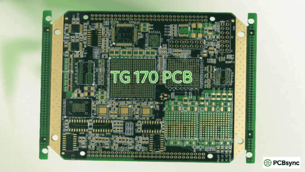
Your operating temperature should stay at least 20-25°C below Tg for reliable long-term performance. A device operating at 110°C with a 130°C Tg material is living on the edge. Upgrade to a 170°C Tg material, and you’ve built in a comfortable safety margin.
Types of PCB Tg Classifications
The industry generally classifies PCB materials into several Tg categories. Here’s a practical breakdown:
Tg Class
Temperature
Typical Applications
Example Materials
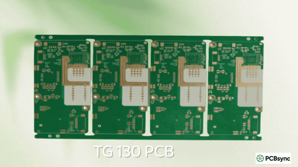
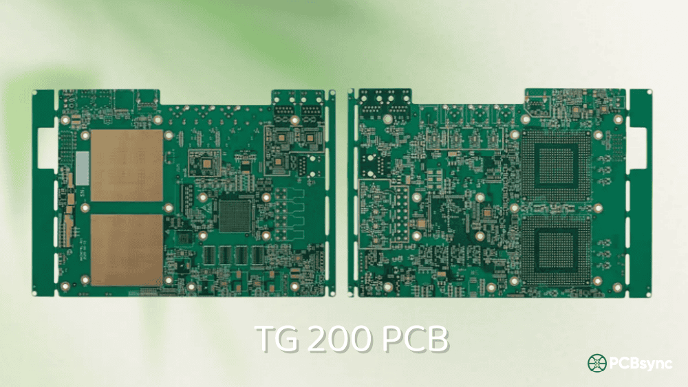
Standard Tg
130-140°C
Consumer electronics, LED lighting, simple 2-4 layer boards
Standard FR-4, TG130, TG135
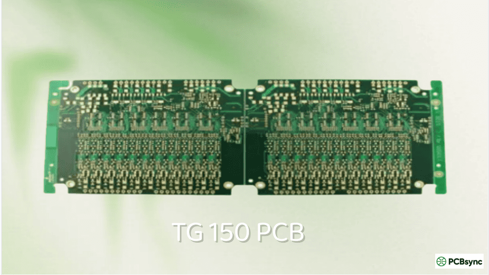
Mid Tg
150-165°C
General lead-free assembly, PLCs, industrial controls
Beyond Tg: Critical Thermal Parameters You Must Know
Tg is important, but it’s not the only thermal property that determines board reliability. Here are the other parameters every PCB engineer should understand:
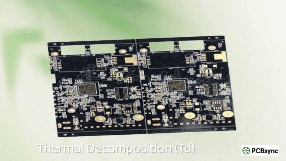
Td (Decomposition Temperature)
Td is the temperature at which the resin begins to chemically decompose, typically measured at 5% weight loss using TGA (Thermogravimetric Analysis). Unlike Tg, Td represents irreversible damage. For lead-free soldering, you want Td above 325°C. Premium materials like Isola 370HR achieve Td values of 340-350°C.
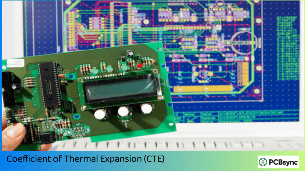
CTE (Coefficient of Thermal Expansion)
CTE measures how much the material expands per degree of temperature increase. The Z-axis CTE is particularly critical for multilayer boards. Below Tg, typical FR-4 has a Z-axis CTE of 50-70 ppm/°C. Above Tg, this can jump to 250+ ppm/°C. High-Tg materials typically have lower CTE values, reducing stress on plated through-holes.
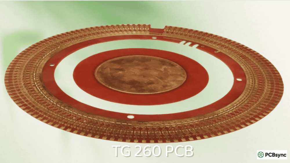
T260, T288, T300 (Time to Delamination)
These tests measure how many minutes a material can withstand specific temperatures (260°C, 288°C, 300°C) before delamination occurs. Per IPC-TM-650 Test Method 2.4.24.1, these values indicate real-world soldering durability. For lead-free assembly, aim for T260 > 30 minutes and T288 > 15 minutes.
You’ll see different Tg values on datasheets depending on the test method used. Understanding these differences helps you compare materials accurately:
DSC (Differential Scanning Calorimetry)
DSC measures heat flow changes as the sample is heated. It detects the step change in heat capacity at Tg. This is the most common method referenced on datasheets and follows ASTM E1356. DSC typically gives the lowest Tg value of the three methods.
TMA (Thermomechanical Analysis)
TMA measures dimensional changes (expansion) as temperature increases. The Tg is identified where the expansion rate changes significantly. This method is particularly useful for understanding how CTE behavior changes at Tg. TMA values typically fall between DSC and DMA results.
DMA (Dynamic Mechanical Analysis)
DMA measures mechanical properties (storage modulus, loss modulus) under oscillating stress. It’s the most sensitive method and best correlates with mechanical performance. DMA typically reports the highest Tg value, often 10-20°C higher than DSC.
Pro Tip: When comparing materials from different manufacturers, make sure you’re comparing Tg values measured by the same method. A material with “Tg 170°C (DMA)” may perform similarly to one rated “Tg 155°C (DSC).”
Choosing the right Tg involves balancing performance requirements against cost and availability. Here’s my practical approach:
Step 1: Determine Your Maximum Operating Temperature
Identify the hottest spot on your board during normal operation. Factor in ambient temperature, component self-heating, and any hot spots from power devices. Add 25°C as a safety margin — this becomes your minimum Tg requirement.
Multiple reflow cycles: Higher Tg and T260 values needed
Rework requirements: Consider T288 values for soldering iron rework
Step 3: Evaluate Board Complexity
Multilayer boards (8+ layers) and HDI designs with microvias benefit more from high-Tg materials due to increased Z-axis stress during thermal cycling. For simple 2-layer consumer boards, standard Tg often suffices.
Step 4: Factor in Environment and Lifespan
Automotive underhood: High Tg (170°C+) with low CTE
Aerospace/military: Ultra-high Tg with CAF resistance
Industrial 24/7 operation: Mid-to-high Tg with excellent T260
Consumer electronics: Standard Tg typically acceptable
Popular High Tg PCB Materials and Manufacturers
When specifying high-Tg materials, here are reliable options from major manufacturers:
Material
Manufacturer
Tg (DSC)
Td
Key Features
Isola 370HR
Isola
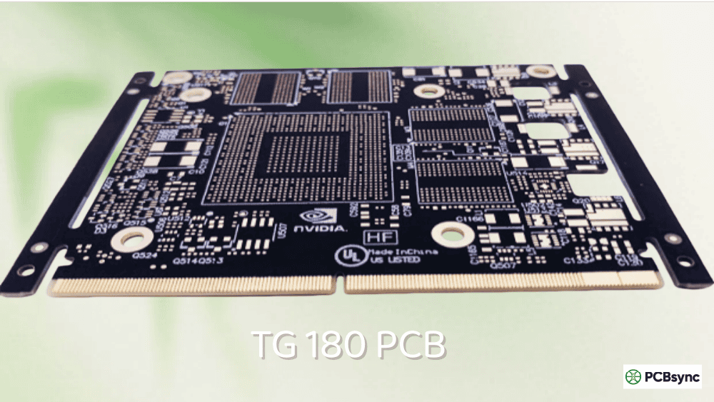
180°C
340°C
CAF resistant, low CTE
Isola FR408HR
Isola
180°C
360°C
High-speed digital, HDI
Ventec VT-47
Ventec
180°C
340°C
Automotive qualified
ITEQ IT-180ITC
ITEQ
175°C
330°C
Halogen-free option
Shengyi S1000-2
Shengyi
180°C
340°C
Cost-effective, widely available
TUC TU-872
TUC
170°C
330°C
Good balance of cost/performance
Industry Applications for High Tg PCBs
Automotive Electronics
Underhood applications regularly see temperatures of 125-150°C. Engine control units, transmission controllers, and ABS systems all require high-Tg materials (typically 170°C+) with excellent thermal cycling resistance. The transition to electric vehicles has only increased these demands, as power electronics generate significant heat.
Aerospace and Defense
Flight control systems, avionics, and missile guidance systems face temperature extremes from -55°C to +125°C or higher. These applications typically specify polyimide (Tg 250-260°C) or ultra-high Tg FR-4 with stringent qualification requirements per MIL-PRF-31032.
Telecommunications and Servers
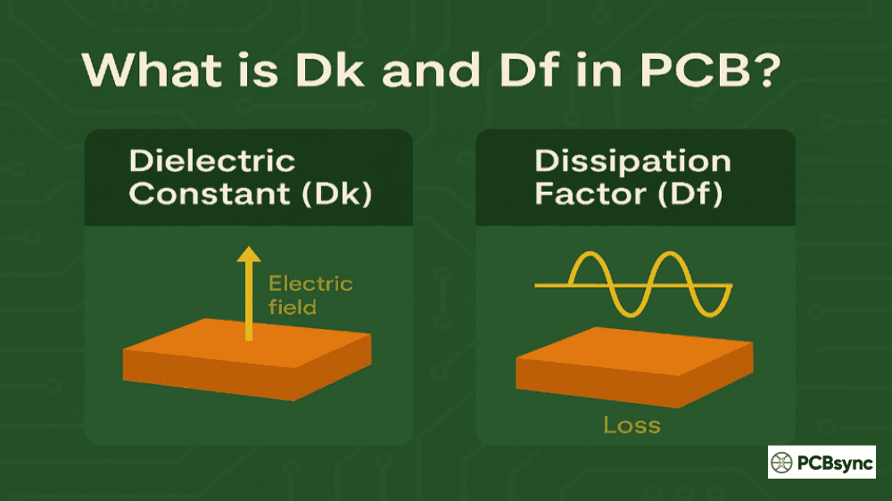
High-density server blades and network switches generate substantial heat from processors and power regulators. Combined with lead-free assembly requirements and 24/7 operation, these applications commonly use high-Tg materials with low Dk/Df for signal integrity at high frequencies.
Industrial and Power Electronics
Motor drives, power supplies, and industrial controllers operate in harsh environments with wide temperature swings. High-Tg materials with excellent CAF (Conductive Anodic Filament) resistance are essential for long-term reliability in humid conditions.
Common PCB Failures Related to Glass Transition Temp (Tg)
Understanding failure modes helps you make better material decisions:
Barrel Cracking
When Z-axis expansion exceeds the ductility of the copper plating in vias, microscopic cracks form. These may pass initial testing but worsen under thermal cycling, eventually causing intermittent or complete open circuits.
Delamination
Separation between layers or between copper and dielectric occurs when internal stresses exceed bond strength. Often caused by moisture absorption combined with rapid heating during soldering.
Pad Cratering
Cracking in the resin beneath surface pads, typically from CTE mismatch between BGA components and the substrate. High-Tg materials with matched CTE help prevent this failure mode.
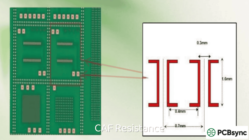
CAF (Conductive Anodic Filament)
Copper migration along glass fibers under voltage bias and humidity, eventually creating short circuits. High-Tg materials with CAF-resistant formulations are essential for automotive and industrial applications.
Best Practices for High Tg PCB Design
Specify material by parameters, not just Tg. Include Td, CTE, T260/T288 requirements on your fabrication drawing.
Use thermal reliefs appropriately. While they help manufacturing, they also affect heat transfer. Balance thermal management with assembly requirements.
Consider via design. Larger via diameters and thicker copper plating improve thermal cycling reliability.
Manage moisture. Bake boards before assembly if they’ve been stored in humid conditions. Moisture trapped in the laminate causes delamination during reflow.
Communicate with your fabricator. Discuss material equivalents and ensure they understand your thermal requirements.
Plan for testing. Include thermal cycling and interconnect stress testing in your qualification plan for high-reliability applications.
Useful Resources and Databases
Here are essential resources for PCB material selection and specifications:
Material Datasheets and Databases
Isola Laminate Selector: isola-group.com/products – Comprehensive datasheets for all Isola materials
Rogers Corporation: rogerscorp.com/advanced-electronics-solutions – High-frequency and high-Tg laminates
Ventec International: ventec-group.com – Automotive and industrial grade materials
IPC-4101: Specification for Base Materials for Rigid and Multilayer Printed Boards
IPC-TM-650 2.4.24: Glass Transition and Cure Factor by DMA and TMA
IPC-TM-650 2.4.24.1: Time to Delamination (T260, T288, T300)
ASTM E1356: Standard Test Method for Glass Transition by DSC
UL 94: Flammability testing for PCB materials
Technical Communities
IPC (ipc.org): Industry standards and training resources
SMTA (smta.org): Surface Mount Technology Association for assembly-related knowledge
IEEE Electronics Packaging Society: Technical papers and conferences
Frequently Asked Questions About PCB Tg
1. What is the difference between Tg and Tm in PCB materials?
Tg (Glass Transition Temperature) is when the material softens from rigid to rubbery — it’s a reversible phase change. Tm (Melting Temperature) is when the material actually melts into a liquid state, which is irreversible and destructive. For thermoset resins like FR-4, true melting doesn’t occur; instead, the material decomposes at Td before reaching a melting point.
2. Do I always need a high Tg PCB for lead-free soldering?
Not always, but it helps significantly. Standard Tg materials (130-140°C) can survive lead-free reflow peaks of 245-260°C because the exposure time is brief. However, high-Tg materials experience less thermal stress, lower CTE expansion, and better long-term reliability. For multilayer boards or products requiring multiple reflow cycles, high Tg is strongly recommended.
3. Why do datasheets show different Tg values for the same material?
Tg values differ based on measurement method. DSC, TMA, and DMA each measure different physical properties (heat flow, expansion, mechanical modulus) and can yield results varying by 10-20°C. Always compare Tg values measured by the same method when evaluating materials, and note which method the datasheet references.
4. How much more expensive are high Tg PCB materials?
High-Tg materials typically add 15-25% to base material costs compared to standard FR-4. However, total PCB cost depends on many factors including layer count, copper weight, and surface finish. For high-reliability applications, the modest material premium provides significant value in reduced field failures and warranty costs.
5. Can operating above Tg permanently damage my PCB?
Brief excursions above Tg (like during reflow soldering) are normal and the material returns to its original state upon cooling. However, prolonged or repeated exposure above Tg accelerates material fatigue, via cracking, and delamination. As a rule, your maximum continuous operating temperature should stay at least 20-25°C below Tg for long-term reliability.
Conclusion
Glass Transition Temperature (Tg) is a fundamental parameter that directly impacts PCB reliability, especially as the industry has moved to lead-free assembly and increasingly demanding thermal environments. By understanding Tg alongside related parameters like Td, CTE, and time to delamination, you can make informed material selections that balance performance, cost, and reliability.
Remember: it’s not about always choosing the highest Tg available. It’s about selecting the right Tg for your specific application, assembly process, and operating environment. Apply the 20-25°C safety margin rule, consider the full thermal picture, and work closely with your fabricator to ensure your boards meet their intended performance requirements.
Whether you’re designing consumer electronics, automotive systems, or aerospace hardware, taking the time to properly specify and understand Tg requirements will save you from costly redesigns and field failures down the road.
Inquire: Call 0086-755-23203480, or reach out via the form below/your sales contact to discuss our design, manufacturing, and assembly capabilities.
Quote: Email your PCB files to Sales@pcbsync.com (Preferred for large files) or submit online. We will contact you promptly. Please ensure your email is correct.
Notes: For PCB fabrication, we require PCB design file in Gerber RS-274X format (most preferred), *.PCB/DDB (Protel, inform your program version) format or *.BRD (Eagle) format. For PCB assembly, we require PCB design file in above mentioned format, drilling file and BOM. Click to download BOM template To avoid file missing, please include all files into one folder and compress it into .zip or .rar format.


