Inquire: Call 0086-755-23203480, or reach out via the form below/your sales contact to discuss our design, manufacturing, and assembly capabilities.
Quote: Email your PCB files to Sales@pcbsync.com (Preferred for large files) or submit online. We will contact you promptly. Please ensure your email is correct.
Notes: For PCB fabrication, we require PCB design file in Gerber RS-274X format (most preferred), *.PCB/DDB (Protel, inform your program version) format or *.BRD (Eagle) format. For PCB assembly, we require PCB design file in above mentioned format, drilling file and BOM. Click to download BOM template To avoid file missing, please include all files into one folder and compress it into .zip or .rar format.
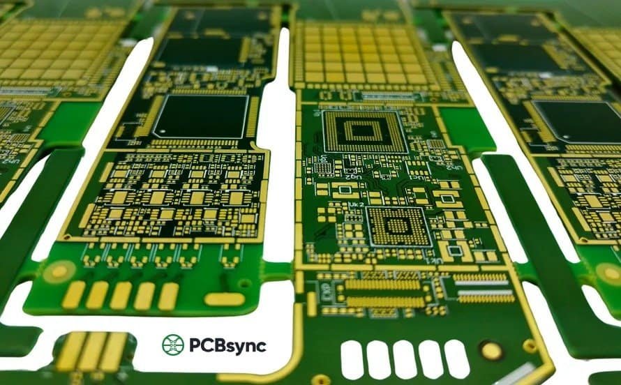
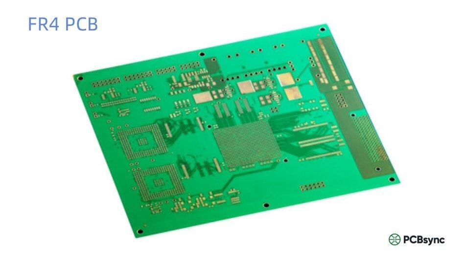
If you’ve spent any time working with printed circuit boards, you’ve almost certainly encountered FR4. It’s the backbone of the electronics industry, found in everything from smartphone motherboards to industrial control systems. But what exactly makes FR4 the go-to material for PCB manufacturing? After 12 years designing boards and troubleshooting production issues, I’ve developed a deep appreciation for this seemingly simple material—and a healthy respect for the problems that arise when you choose the wrong variant.
This guide breaks down everything you need to know about FR4 PCB material: what it is, how to select the right thickness and Tg rating, when standard FR4 won’t cut it, and practical tips I’ve learned the hard way. Whether you’re a design engineer specifying your first board or a procurement specialist trying to understand why your supplier is recommending FR4-TG170 over standard FR4, this article will give you the knowledge to make informed decisions.
FR4 stands for “Flame Retardant 4,” a designation established by the National Electrical Manufacturers Association (NEMA). It refers to a grade of glass-reinforced epoxy laminate material that meets specific flammability and performance standards. The “4” indicates the material’s grade classification—not a version number, as some newcomers assume.
At its core, FR4 PCB material consists of woven fiberglass cloth impregnated with an epoxy resin binder. This combination creates a substrate that’s mechanically strong, electrically insulating, and thermally stable enough for most electronic applications. The fiberglass provides structural rigidity while the epoxy resin fills the gaps and bonds everything together, creating a laminate that can withstand the stresses of component mounting, soldering, and long-term operation.
FR4 Material Composition and Structure
Understanding FR4’s composition helps explain its properties. The woven fiberglass fabric (typically E-glass) accounts for roughly 60% of the material by weight. This glass weave comes in different styles—the most common being 7628, 2116, and 1080—each with different thread counts and thicknesses that affect the final laminate’s properties.
The remaining 40% consists of brominated epoxy resin, which provides flame retardancy (hence the “FR” designation). This bromine content is what allows FR4 to self-extinguish when removed from a flame source, achieving the UL94 V-0 rating required for most electronic applications. Some manufacturers now offer halogen-free variants for environmentally sensitive applications, though these typically come at a cost premium.
Key FR4 PCB Properties
The following table summarizes the critical electrical, thermal, and mechanical properties of standard FR4 material:
Property
Typical Value
Test Standard
Dielectric Constant (Dk)
4.2 – 4.7 @ 1MHz
IPC-TM-650 2.5.5.3
Dissipation Factor (Df)
0.017 – 0.025 @ 1MHz
IPC-TM-650 2.5.5.3
Volume Resistivity
10^8 MΩ·cm
IPC-TM-650 2.5.17.1
Surface Resistivity
10^6 MΩ
IPC-TM-650 2.5.17.1
Flexural Strength (Lengthwise)
415 MPa (60,000 psi)
IPC-TM-650 2.4.4
Thermal Conductivity
0.3 W/m·K
ASTM E1461
CTE (Z-axis)
50-70 ppm/°C
IPC-TM-650 2.4.24
Moisture Absorption
0.10% – 0.15%
IPC-TM-650 2.6.2.1
Flammability Rating
UL94 V-0
UL94
A few notes on these values: the dielectric constant varies with frequency, which matters for RF and high-speed digital designs. Standard FR4 isn’t ideal above about 1-2 GHz because the Dk and Df both degrade at higher frequencies. The Z-axis CTE (coefficient of thermal expansion) is particularly important for reliability—it’s significantly higher than the X-Y axes due to the resin’s properties, which can stress plated through-holes during thermal cycling.
FR4 PCB Thickness Options
One of the first decisions you’ll make when designing an FR4 PCB is selecting the board thickness. While 1.6mm FR4 has become the industry standard—so much so that many designers specify it automatically—there are good reasons to consider other options depending on your application requirements.
Smartphones, tablets, laptop peripherals, portable medical devices
1.0mm FR4
39 mil
General consumer electronics, LED lighting modules, control boards
1.2mm FR4
47 mil
Computer peripherals, automotive sub-systems, mid-range power electronics
1.6mm FR4
62 mil
Industry standard: motherboards, industrial controls, most general-purpose PCBs
2.0mm FR4
79 mil
Power supplies, motor controllers, high-current applications, backplanes
2.4mm FR4
94 mil
Heavy copper boards, high-power industrial equipment, server backplanes
3.2mm FR4
126 mil
Extra-thick power boards, high-vibration environments, structural applications
Why 1.6mm FR4 Became the Industry Standard
The dominance of 1.6mm FR4 PCB isn’t arbitrary. This thickness hits a sweet spot for several practical reasons. It’s rigid enough to handle standard through-hole and surface mount components without excessive flexing, yet thin enough to keep material costs reasonable. Most importantly, 1.6mm aligns with standard card-edge connector specifications and fits perfectly in industry-standard enclosure slots and card guides.
From a manufacturing perspective, 1.6mm FR4 boards are the most cost-effective because they require no special handling or process adjustments. Thinner boards need more careful handling to prevent warping, while thicker boards may require modified drilling parameters. When you specify 1.6mm, you’re working within every fab house’s comfort zone.
Working with Thin FR4 (0.2mm – 0.8mm)
Thin FR4 PCB materials—particularly 0.2mm FR4, 0.4mm FR4, and 0.6mm FR4—require special attention during design and manufacturing. I’ve seen plenty of projects run into trouble because designers didn’t account for the unique challenges of ultra-thin substrates.
Key considerations for thin FR4 PCB designs:
Panelization is critical. Thin boards absolutely must be panelized with adequate breakaway tabs and support structures. A 0.4mm FR4 board shipped as a singleton will arrive warped.
Aspect ratios become limiting. With 0.2mm material, your minimum drill size may need to increase because maintaining reliable plating in very thin holes is challenging.
Reflow profiles need adjustment. Thin boards heat up and cool down faster, which affects solder joint formation. Your assembly house needs to know the thickness upfront.
Component weight matters. Heavy transformers or connectors can stress thin substrates. Consider mechanical reinforcement or choose a thicker material for high-mass components.
Understanding FR4 Tg: Glass Transition Temperature
If thickness is about mechanical considerations, Tg (glass transition temperature) is about thermal performance. The Tg of FR4 material indicates the temperature at which the epoxy resin transitions from a rigid, glassy state to a softer, rubbery state. Above this temperature, the material’s mechanical and electrical properties degrade significantly.
This doesn’t mean your board fails at Tg—it’s not a maximum operating temperature. But prolonged exposure above Tg accelerates aging and can cause delamination, particularly during lead-free soldering processes where peak temperatures can exceed 250°C.
FR4 Tg Grades Comparison
FR4 Grade
Tg Value
Td Value
Cost Index
Recommended Use
Standard FR4
130-140°C
300°C
1.0x
Consumer electronics, low-temp processes
FR4 TG135
135°C
300°C
1.0x
Basic applications, SnPb soldering
FR4 TG150
150°C
320°C
1.1x
General lead-free assembly, moderate temps
FR4 TG170
170°C
340°C
1.15-1.2x
Lead-free, multilayer, automotive
High-Tg FR4
180°C+
350°C+
1.3-1.5x
High-reliability, aerospace, military
Selecting the Right Tg for Your Application
Standard FR4 (Tg 130-140°C)
Standard FR4 material works fine for many consumer electronics, especially those using traditional tin-lead solder. If your product operates at room temperature, won’t see multiple rework cycles, and doesn’t have demanding reliability requirements, standard FR4 keeps costs down without sacrificing quality. This is what you’ll get if you don’t specify otherwise, and for many applications, that’s perfectly acceptable.
FR4 TG150
FR4 TG150 represents a modest step up that provides better margin during lead-free assembly. The peak temperatures in a typical lead-free reflow profile (around 245-260°C) are well above standard FR4’s Tg, meaning the material softens during soldering. While boards usually survive this, FR4 TG150 provides additional thermal margin that improves yield and reduces the risk of subtle damage that might cause field failures.
FR4 TG170: The Lead-Free Standard
FR4 TG170 has become the de facto standard for lead-free manufacturing, particularly for multilayer boards. The higher Tg provides comfortable margin above lead-free soldering temperatures, and the improved Td (decomposition temperature) means the material can withstand multiple reflow cycles without degradation—critical if your boards require rework or have components on both sides.
I recommend FR4 TG170 for any board with 6+ layers, any automotive application, and any product expected to last more than 5 years. The cost premium (typically 15-20% over standard FR4) is negligible compared to field failure costs.
High-Tg FR4 (180°C and Above)
For aerospace, military, and high-reliability industrial applications, high-Tg FR4 materials rated at 180°C or higher provide maximum thermal stability. These materials use modified resin systems that maintain their properties at elevated temperatures, resist moisture better, and have lower Z-axis expansion—all critical factors for boards that must operate reliably in harsh environments for decades.
FR4 PCB vs Alternative Materials
While FR4 dominates the PCB market, it’s not the right choice for every application. Understanding when to consider alternatives can save you from performance problems—or unnecessary costs.
Material
Dk
Df
Max Freq
Cost
Best For
FR4
4.2-4.7
0.017-0.025
~1-2 GHz
$
General purpose
Rogers 4350B
3.48
0.0037
10+ GHz
$$$
RF/Microwave
Isola 370HR
4.04
0.021
~3 GHz
$$
High-speed digital
Polyimide
3.4
0.002
~2 GHz
$$$
High-temp, flex
CEM-1
4.5
0.030
<500 MHz
$
Single-sided, cost-critical
Aluminum Base
4.0-5.0
0.020
<1 GHz
$$
LED, power, thermal
The key insight here is that FR4 works well up to about 1-2 GHz, beyond which signal integrity suffers. For high-speed designs running at multi-gigabit data rates, the signal loss through FR4 can cause eye diagram closure and bit errors. That’s when you need to consider low-loss materials like Isola 370HR or Rogers products.
Common FR4 PCB Applications by Industry
Consumer Electronics
Consumer electronics account for the largest volume of FR4 PCB production. Smartphones, tablets, laptops, televisions, gaming consoles, and home appliances all rely on FR4 as their primary substrate material. The combination of acceptable electrical performance, mechanical durability, and low cost makes FR4 ideal for high-volume consumer products.
Typical specifications: 4-8 layer boards, 0.8mm-1.6mm FR4 thickness, FR4 TG150 or TG170 for lead-free assembly, controlled impedance for USB, HDMI, and display interfaces.
Automotive Electronics
Automotive applications demand FR4 TG170 or higher due to under-hood temperatures and strict reliability requirements. Engine control units, infotainment systems, body control modules, and advanced driver assistance systems (ADAS) all use FR4 PCBs qualified to AEC-Q100 standards. The thermal cycling in automotive environments—from -40°C to +125°C—tests FR4’s limits, which is why high-Tg materials with low Z-axis CTE are essential.
Industrial and Medical Equipment
Industrial control systems, programmable logic controllers (PLCs), motor drives, and medical devices use FR4 extensively. These applications often specify thicker materials (1.6mm-2.4mm) for mechanical robustness and may require high-Tg variants for elevated operating temperatures. Medical devices additionally require UL recognition and often specify halogen-free FR4 for environmental compliance.
Practical Design Tips for FR4 PCBs
After designing hundreds of FR4 boards, certain lessons keep recurring. Here are the tips I wish someone had given me when I started:
Always specify your stackup explicitly. Don’t assume the fab house will use the same FR4 variant on every layer. For controlled impedance designs, specify the Dk value you’re designing for and request stackup confirmation before fabrication.
Account for Dk variation with frequency. If you’re calculating trace impedance for high-speed signals, don’t use the 1MHz Dk value. Request Dk at your operating frequency—most FR4 suppliers can provide this data.
Consider moisture sensitivity. FR4 absorbs moisture, which affects Dk and mechanical properties. For products shipping to humid environments, consider conformal coating or specify low-moisture-absorption variants.
Match your Tg to your assembly process. If your board will see multiple reflow cycles (double-sided SMT, rework), step up to FR4 TG170 even if operating temperatures don’t require it.
Don’t over-specify. Using Rogers material for a 50MHz clock circuit wastes money. Standard FR4 handles most applications just fine—save the specialty materials for where they’re actually needed.
Useful Resources and Datasheets
The following resources provide detailed specifications and technical data for FR4 materials and PCB design:
Resource
Description
IPC Standards (ipc.org)
IPC-4101 specifies base materials for rigid PCBs; IPC-2221 covers generic design standards
Isola Group (isola-group.com)
Datasheets for FR408HR, IS415, 370HR and other high-performance laminates
Rogers Corporation (rogerscorp.com)
Complete specifications for RO4350B, RO4003C, and other RF materials
Nan Ya Plastics (nanyaplastics.com)
FR4 and high-Tg laminate specifications from a major material supplier
NEMA Standards (nema.org)
Original FR4 grade definitions and performance requirements
UL iQ Database (iq.ul.com)
Verify UL certification status for specific laminate products
Saturn PCB Toolkit
Free impedance calculator and PCB design utilities (saturnpcb.com)
Frequently Asked Questions About FR4 PCB
What does FR4 stand for in PCB?
FR4 stands for “Flame Retardant 4,” a grade designation defined by NEMA (National Electrical Manufacturers Association). The “FR” indicates the material’s flame-retardant properties—specifically its ability to self-extinguish after ignition, meeting UL94 V-0 standards. The “4” designates this specific grade of glass-reinforced epoxy laminate, distinguishing it from other FR grades like FR1, FR2 (paper-based), and FR3 (cotton paper-epoxy). FR4 has become the dominant PCB material due to its excellent balance of electrical, mechanical, and thermal properties.
What is the difference between FR4 TG135, TG150, and TG170?
The numbers refer to the glass transition temperature (Tg) in degrees Celsius. FR4 TG135 transitions to a softer state at 135°C, while FR4 TG150 and FR4 TG170 maintain rigidity up to 150°C and 170°C respectively. In practice, FR4 TG135 is suitable for traditional tin-lead soldering and low-temperature applications. FR4 TG150 provides modest improvement for lead-free assembly. FR4 TG170 has become the standard for lead-free manufacturing, multilayer boards, and automotive applications because it maintains structural integrity throughout multiple reflow cycles at 250°C+ peak temperatures. Higher Tg materials cost 15-20% more but significantly improve long-term reliability.
Can FR4 be used for RF and microwave circuits?
FR4 works acceptably for RF applications up to about 1-2 GHz, but its performance degrades significantly at higher frequencies. The main limitations are its relatively high dielectric constant (Dk ~4.5), which is less stable across frequencies, and its dissipation factor (Df ~0.02), which causes signal loss. For microwave circuits above 2 GHz, designers typically choose low-loss materials like Rogers RO4350B (Dk 3.48, Df 0.0037) or similar PTFE-based laminates. That said, many WiFi (2.4 GHz), Bluetooth, and GPS designs successfully use FR4 by accepting some performance compromise in exchange for lower cost.
Is FR4 RoHS compliant?
Standard FR4 materials are generally RoHS compliant because they don’t contain the restricted substances (lead, mercury, cadmium, hexavalent chromium, PBB, and PBDE) above threshold limits. However, FR4 does contain brominated flame retardants, which are not restricted under RoHS but are under other environmental regulations like REACH. For applications requiring halogen-free materials, manufacturers offer FR4-equivalent products with non-brominated flame retardants—these are sometimes called “green” FR4 and typically cost 10-15% more than standard FR4. Always request material certifications from your PCB supplier for compliance documentation.
What is the maximum operating temperature for FR4 PCB?
The maximum continuous operating temperature for FR4 depends on the specific grade. Standard FR4 (Tg 130-140°C) is typically rated for continuous operation up to 110-120°C. FR4 TG170 can operate continuously at 130-150°C. These ratings assume the board won’t experience significant mechanical stress. Short-term exposure during soldering (peaks of 250-260°C for 10-30 seconds) is acceptable, which is why FR4 survives reflow processes. However, repeated thermal cycling or prolonged exposure above Tg will degrade the material, causing delamination and reliability issues. For applications requiring sustained high temperatures above 150°C, consider polyimide-based materials instead of FR4.
Conclusion
FR4 PCB material has earned its position as the electronics industry’s workhorse through decades of proven performance. From 0.2mm ultra-thin substrates to 3.2mm power boards, from standard Tg to FR4 TG170 and beyond, this versatile material family covers an enormous range of applications.
The key takeaways: specify 1.6mm FR4 as your default unless your application specifically requires otherwise. Use FR4 TG170 for lead-free assembly and any board with 6+ layers. Don’t use FR4 above 2 GHz without accepting performance compromises. And always verify your stackup with the fabricator before committing to production.
Getting these decisions right won’t make your product revolutionary, but getting them wrong can cause expensive field failures. FR4’s ubiquity means you can find fabricators and assembly houses worldwide who know how to work with it—that alone makes it the safe choice for most designs. When you need something more specialized, you’ll know, and then you can explore the alternatives. Until then, FR4 will serve you well.
Inquire: Call 0086-755-23203480, or reach out via the form below/your sales contact to discuss our design, manufacturing, and assembly capabilities.
Quote: Email your PCB files to Sales@pcbsync.com (Preferred for large files) or submit online. We will contact you promptly. Please ensure your email is correct.
Notes: For PCB fabrication, we require PCB design file in Gerber RS-274X format (most preferred), *.PCB/DDB (Protel, inform your program version) format or *.BRD (Eagle) format. For PCB assembly, we require PCB design file in above mentioned format, drilling file and BOM. Click to download BOM template To avoid file missing, please include all files into one folder and compress it into .zip or .rar format.


