Inquire: Call 0086-755-23203480, or reach out via the form below/your sales contact to discuss our design, manufacturing, and assembly capabilities.
Quote: Email your PCB files to Sales@pcbsync.com (Preferred for large files) or submit online. We will contact you promptly. Please ensure your email is correct.
Notes: For PCB fabrication, we require PCB design file in Gerber RS-274X format (most preferred), *.PCB/DDB (Protel, inform your program version) format or *.BRD (Eagle) format. For PCB assembly, we require PCB design file in above mentioned format, drilling file and BOM. Click to download BOM template To avoid file missing, please include all files into one folder and compress it into .zip or .rar format.
Designing a custom PCB around the ESP32 is one of the most rewarding projects you can tackle. The combination of WiFi, Bluetooth, and powerful processing in a single module makes the ESP32 perfect for IoT products, smart home devices, and countless embedded applications. But when you open Altium Designer to start your design, you quickly realize something: finding a reliable ESP32 Altium Designer Library isn’t as straightforward as you’d hope.
I’ve spent considerable time hunting down ESP32 libraries, creating my own when necessary, and learning what separates a usable library from one that leads to manufacturing headaches. This guide covers everything you need: where to download free ESP32 libraries, how to import them into Altium, critical PCB design considerations for RF performance, and tips for creating your own libraries when you can’t find what you need.
Before downloading any ESP32 Altium Designer Library, you need to understand which ESP32 variant you’re designing with. Espressif offers multiple module families, each with different pinouts, dimensions, and capabilities.
ESP32 Module Family Overview
Module
Chip
Flash
PSRAM
Antenna
Dimensions (mm)
ESP32-WROOM-32E
ESP32-D0WD-V3
4-16MB
None
PCB
18 x 25.5 x 3.1
ESP32-WROOM-32UE
ESP32-D0WD-V3
4-16MB
None
U.FL
18 x 19.2 x 3.2
ESP32-WROVER-E
ESP32-D0WD-V3
4-16MB
8MB
PCB
18 x 31.4 x 3.3
ESP32-WROVER-IE
ESP32-D0WD-V3
4-16MB
8MB
U.FL
18 x 31.4 x 3.3
ESP32-S3-WROOM-1
ESP32-S3
4-16MB
2-8MB
PCB
18 x 25.5 x 3.1
ESP32-C3-WROOM-02
ESP32-C3
4MB
None
PCB
18 x 20 x 3.2
The WROOM series is the most commonly used for general IoT applications, while WROVER modules include additional PSRAM for memory-intensive applications like image processing or large data buffers.
Choosing Between ESP32 Chip Variants
The ESP32 family has expanded significantly since the original chip launched. Each variant targets different applications:
Variant
CPU
Cores
Max Freq
WiFi
Bluetooth
Best For
ESP32 (Original)
Xtensa LX6
2
240 MHz
802.11 b/g/n
Classic + BLE
General IoT, audio
ESP32-S2
Xtensa LX7
1
240 MHz
802.11 b/g/n
None
USB devices, low power
ESP32-S3
Xtensa LX7
2
240 MHz
802.11 b/g/n
BLE 5.0
AI/ML, vector processing
ESP32-C3
RISC-V
1
160 MHz
802.11 b/g/n
BLE 5.0
Cost-sensitive, secure IoT
ESP32-C6
RISC-V
1
160 MHz
WiFi 6
BLE 5.0
Matter, Thread, Zigbee
Understanding these differences helps you select the right library and design your schematic correctly.
Where to Download ESP32 Altium Designer Libraries
Finding quality ESP32 libraries requires knowing where to look. Here are the most reliable sources I’ve used over the years.
SnapEDA (SnapMagic Search)
SnapEDA offers free, verified ESP32 libraries with schematic symbols, footprints, and 3D models. Their libraries follow IPC-7351B standards for footprints.
Available ESP32 Parts:
ESP32-WROOM-32D/32E
ESP32-WROVER series
ESP32-DEVKITC development boards
ESP32-S2 and ESP32-S3 modules
ESP32-C3 modules
Download Process:
Visit snapeda.com and search for your ESP32 module
Select “Altium” as the export format
Download the .zip file containing .SchLib and .PcbLib files
Extract and import into your Altium project
Ultra Librarian
Ultra Librarian provides manufacturer-verified symbols and footprints, including 3D STEP models for mechanical verification.
Key Features:
Free registration required
Supports multiple Altium format exports
Includes detailed 3D models
Regular updates from Espressif
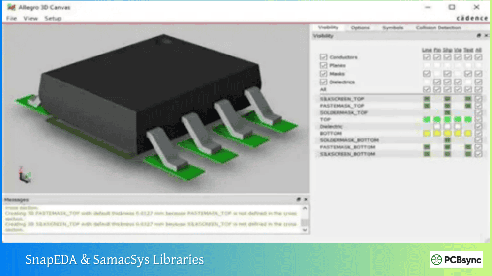
SamacSys (Component Search Engine)
SamacSys offers the Library Loader plugin that integrates directly into Altium Designer, allowing you to search and add components without leaving the software.
Installation Steps:
Download Library Loader from samacsys.com
Run the installer and select Altium Designer
Restart Altium Designer
Access via File → Symbols | Footprints | 3D Models
Search for ESP32 and add directly to your design
GitHub Community Libraries
Several community-maintained repositories offer ESP32 libraries:
Repository
Contents
Notes
ryankurte/altium-library
ESP32 footprints
Database-backed library
fedecastellaro/ESP32-S3-SYMBOL-FOOTPRINT
ESP32-S3
Based on official datasheet
DenizYapici/ESP32-WROOM-Project
Complete project
Includes schematic examples
Downloading from GitHub:
Navigate to the repository
Click “Code” → “Download ZIP”
Extract files to your Altium libraries folder
Add .SchLib and .PcbLib files to your project
PCB Libraries (Footprint Expert)
PCB Libraries provides professional-grade footprints that can be configured for different pad sizes and tolerances. They offer ESP32 footprints as part of their Espressif component collection.
How to Import ESP32 Libraries into Altium Designer
Once you’ve downloaded your ESP32 Altium Designer Library files, proper installation ensures they work correctly across all your projects.
Installing Individual Library Files
For .SchLib and .PcbLib files downloaded separately:
Open Altium Designer
Navigate to the Components panel
Click the menu icon (three lines) and select File-based Libraries Preferences
In the Installed tab, click Install
Browse to your downloaded .SchLib file and click Open
Repeat for the .PcbLib file
Click Close to finish
The libraries now appear in your Components panel and are available for all projects.
Adding Libraries to a Specific Project
For project-specific libraries:
Open your project in Altium
Right-click the project name in the Projects panel
Select Add Existing to Project
Navigate to your library files and select them
The libraries appear under your project structure
Installing Integrated Libraries
Some downloads come as .IntLib (Integrated Library) files:
Go to Components panel
Open File-based Libraries Preferences
Click Install and select the .IntLib file
The integrated library contains both symbols and footprints linked together
Verifying Library Installation
After installation, verify everything works:
Open the Components panel
Type “ESP32” in the search box
You should see your imported components
Click a component to preview the symbol
Check the footprint tab to verify the PCB footprint
Examine 3D model if available
Critical PCB Design Guidelines for ESP32
The ESP32 contains sensitive RF circuitry that requires careful PCB layout. Following Espressif’s guidelines ensures reliable wireless performance.
Antenna Keepout Zone Requirements
For modules with PCB antennas (WROOM, WROVER without U.FL), maintain a strict keepout zone:
Keepout Requirements:
Minimum 15mm clearance in all directions around the antenna area
No copper on ANY layer within the keepout zone (including ground planes)
No components within the keepout zone
No traces, vias, or pads in this area
If your board extends under the antenna area, Espressif recommends cutting away that portion of the PCB to minimize interference.
Layer Stack Recommendations
Espressif recommends specific layer configurations for optimal RF performance:
Four-Layer Stack (Recommended):
Layer
Function
Notes
Layer 1 (TOP)
Signal traces, components
Route most signals here
Layer 2 (GND)
Solid ground plane
No traces—keep complete
Layer 3 (POWER)
Power traces, some signals
Maintain GND under RF/crystal
Layer 4 (BOTTOM)
Few signals
Avoid components on this layer
Two-Layer Stack:
Layer
Function
Notes
Layer 1 (TOP)
Signals, components
Include power traces
Layer 2 (BOTTOM)
Ground plane
Keep complete under RF/crystal
RF Trace Guidelines
When routing RF signals (applicable mainly when designing with raw ESP32 chips rather than modules):
Maintain 50Ω impedance for RF traces
Keep RF trace width typically >20mil for two-layer boards
Use smooth bends—avoid 90° angles
Keep RF traces away from high-speed digital signals
Route RF traces on the top layer only
Power Supply Decoupling
Proper decoupling ensures stable operation:
Place 10µF capacitor at power input
Add 0.1µF capacitors near each VDD pin
Use short, wide traces for power connections
Connect ground pads directly to ground plane (not via traces)
Add at least nine ground vias under the module’s ground pad
Boot Mode Pin Configuration
Several GPIO pins control boot mode and require careful handling:
Pin
Boot Function
Recommendation
GPIO0
Boot mode select
Pull-up with button to GND for programming
GPIO2
Must be low or floating
Don’t pull high during boot
GPIO12
Flash voltage select
Leave floating or pull low for 3.3V flash
GPIO15
JTAG debug
Pull-up to suppress boot messages
EN
Chip enable
RC delay circuit (10kΩ + 1µF)
Creating Your Own ESP32 Library in Altium
Sometimes available libraries don’t match your specific module variant or have errors. Creating your own library ensures accuracy.
Creating the Schematic Symbol
Start with Espressif’s official datasheet for accurate pin definitions:
Select File → New → Library → Schematic Library
Save as “ESP32_Modules.SchLib”
Right-click and select Tools → New Component
Name it based on the exact part number (e.g., “ESP32-WROOM-32E”)
For the ESP32-WROOM-32E, create pins for:
Pin Group
Pins
Electrical Type
Power
3V3, GND (multiple)
Power Input
Enable
EN
Input
Boot
GPIO0
Bidirectional
UART
TXD0, RXD0
Output/Input
SPI
CLK, MOSI, MISO, CS
Bidirectional
I2C
SDA, SCL
Bidirectional
ADC
GPIO32-39
Bidirectional
GPIO
Remaining GPIOs
Bidirectional
Organize pins logically—power on one side, communication interfaces grouped together, general GPIO on another side.
Creating the PCB Footprint
The footprint requires precise dimensions from Espressif’s datasheet:
Select File → New → Library → PCB Library
Save as “ESP32_Modules.PcbLib”
Create a new component matching your schematic symbol name
ESP32-WROOM-32E Footprint Specifications:
38 castellated pads (0.9mm × 1.5mm recommended)
1.27mm pad pitch
Large ground pad (center): approximately 6mm × 6mm
Overall module dimensions: 18mm × 25.5mm
Creating the Footprint:
Set grid to 0.1mm or smaller for precision
Place SMD pads according to datasheet dimensions
Draw the component outline on the Top Overlay layer
Add the antenna keepout zone on a mechanical layer
Espressif provides reference designs that include complete Altium projects:
ESP32-DevKitC reference design
ESP32-WROVER-KIT reference design
ESP-EYE camera board reference
These projects are invaluable for understanding proper layout techniques.
Frequently Asked Questions
Which ESP32 module should I use for a new design?
For most new designs, I recommend the ESP32-WROOM-32E or ESP32-S3-WROOM-1. The WROOM-32E offers proven reliability with WiFi and Bluetooth Classic support, while the S3 variant adds AI acceleration and native USB. If you need external PSRAM for memory-intensive applications, consider the WROVER-E series. For cost-sensitive designs where Bluetooth isn’t needed, the ESP32-C3-WROOM-02 offers excellent value with modern security features.
Can I use ESP32 libraries designed for older module versions?
Use caution when using libraries for older module versions. While the pinout might be identical, dimensions and pad sizes can vary between module revisions. For example, ESP32-WROOM-32D and ESP32-WROOM-32E have the same pinout but slightly different recommended footprints. Always verify the footprint against the current datasheet for your specific part number. Manufacturing a board with an incorrect footprint wastes time and money.
How critical is the antenna keepout zone?
The antenna keepout zone is absolutely critical for reliable wireless performance. I’ve seen designs where engineers ignored this guideline and achieved only 50% of the expected range. Copper near the antenna—even on inner layers—detunes the antenna and increases return loss. If you cannot maintain the full 15mm clearance, test your design thoroughly and consider using a module with U.FL connector and external antenna instead.
Do I need a four-layer board for ESP32 designs?
A four-layer board isn’t strictly required but is strongly recommended for professional products. Two-layer designs can work but require more careful layout, especially maintaining a complete ground plane under the RF section. For hobby projects or simple applications, two layers often suffice. For production designs where wireless performance and reliability matter, invest in four layers.
How do I verify my ESP32 footprint is correct before manufacturing?
Print your PCB layout at 1:1 scale on paper and physically place the ESP32 module on the printout. Verify that all pads align with the module’s castellated edges. Check the ground pad dimensions and position. If you have access to a module, this physical verification catches footprint errors before you commit to fabrication. Additionally, use Altium’s 3D view with an accurate STEP model to check for clearance issues.
Getting Started with Your ESP32 Design
With the right ESP32 Altium Designer Library and proper design techniques, creating custom ESP32 boards becomes straightforward. Start by downloading libraries from the trusted sources listed above, verify them against Espressif’s datasheets, and pay close attention to the RF layout guidelines.
The ESP32 platform’s flexibility means you can design everything from simple WiFi-connected sensors to complex AI-enabled devices. Whether you’re building a commercial product or a personal project, taking time to get the PCB design right pays dividends in reliable operation and strong wireless performance.
Remember that Espressif’s hardware design guidelines document is your primary reference for layout questions. When in doubt, follow their recommendations—they’ve optimized these guidelines through extensive testing across thousands of production designs.
Your first custom ESP32 board is an exciting milestone. With quality libraries and careful attention to RF layout, you’ll have a working design that performs as well as commercial development boards.
Inquire: Call 0086-755-23203480, or reach out via the form below/your sales contact to discuss our design, manufacturing, and assembly capabilities.
Quote: Email your PCB files to Sales@pcbsync.com (Preferred for large files) or submit online. We will contact you promptly. Please ensure your email is correct.
Notes: For PCB fabrication, we require PCB design file in Gerber RS-274X format (most preferred), *.PCB/DDB (Protel, inform your program version) format or *.BRD (Eagle) format. For PCB assembly, we require PCB design file in above mentioned format, drilling file and BOM. Click to download BOM template To avoid file missing, please include all files into one folder and compress it into .zip or .rar format.


