Inquire: Call 0086-755-23203480, or reach out via the form below/your sales contact to discuss our design, manufacturing, and assembly capabilities.
Quote: Email your PCB files to Sales@pcbsync.com (Preferred for large files) or submit online. We will contact you promptly. Please ensure your email is correct.
Notes: For PCB fabrication, we require PCB design file in Gerber RS-274X format (most preferred), *.PCB/DDB (Protel, inform your program version) format or *.BRD (Eagle) format. For PCB assembly, we require PCB design file in above mentioned format, drilling file and BOM. Click to download BOM template To avoid file missing, please include all files into one folder and compress it into .zip or .rar format.
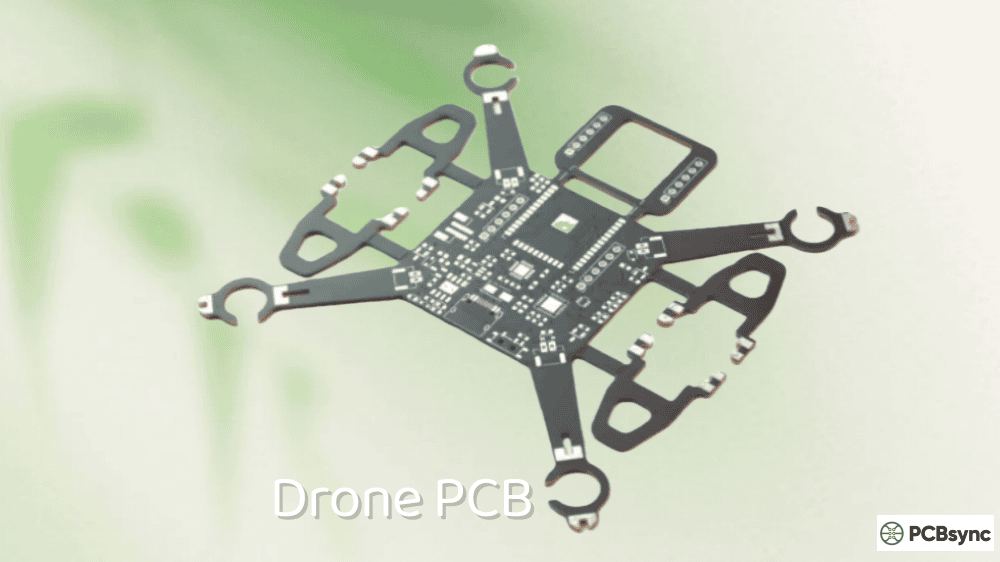
As someone who’s spent over a decade designing circuit boards for unmanned aerial vehicles, I can tell you that drone PCB design represents one of the most demanding applications of IoT PCB technology today. A drone is essentially a flying IoT device—it collects sensor data, processes information in real-time, communicates wirelessly, and operates on limited battery power. Getting the PCB design right means the difference between a drone that flies smoothly for 30 minutes and one that crashes on its first takeoff.
This guide walks you through everything I’ve learned about designing, laying out, and manufacturing circuit boards for drones. Whether you’re building a racing quadcopter, an agricultural survey drone, or an industrial inspection UAV, the principles remain largely the same.
A drone PCB (printed circuit board) serves as the central nervous system of any unmanned aerial vehicle. It mechanically supports and electrically connects all the electronic components that make flight possible—from the microcontroller running stabilization algorithms to the motor drivers spinning the propellers.
What makes drone circuit boards unique compared to standard IoT PCB applications is the combination of constraints they face simultaneously:
Weight restrictions directly impact flight time. Every gram matters when you’re fighting gravity, so the board needs to be as light as possible while still housing all necessary components.
Vibration and shock from motors and crashes require robust mechanical design. Cold solder joints or cracked traces will cause mid-flight failures.
High current paths for motor drivers must coexist with sensitive analog signals from gyroscopes and accelerometers on the same board.
Wireless communication requirements for control links, video transmission, and GPS reception create EMI challenges that demand careful layout planning.
Understanding these constraints from the start shapes every decision in the design process.
Essential Components of a Drone Circuit Board
Before diving into layout considerations, let’s examine the building blocks that make up a functional drone PCB. Each component plays a specific role, and understanding their requirements helps optimize placement and routing.
Flight Controller (FC)
The flight controller is the brain of your drone. It processes sensor data, executes stabilization algorithms, and outputs motor commands hundreds of times per second. Most modern flight controllers use ARM Cortex-M processors like the STM32F4 or STM32F7 series.
Key specifications to consider:
Parameter
Typical Range
Impact on Design
Clock Speed
168-480 MHz
Higher speeds need better decoupling
Flash Memory
512KB-2MB
Determines firmware complexity
GPIO Count
40-100+ pins
Affects routing density
Operating Voltage
3.3V
Requires stable regulation
Package Type
LQFP64-100, QFN
QFN offers better thermal performance
The processor needs clean power, proper decoupling capacitors (typically 100nF ceramic close to each VDD pin plus 10µF bulk capacitors), and careful attention to the crystal oscillator layout.
Inertial Measurement Unit (IMU)
The IMU combines accelerometers and gyroscopes to sense the drone’s orientation and movement. This is arguably the most critical sensor on the board because flight stability depends entirely on accurate IMU readings.
Common IMU choices include the MPU-6000, ICM-20689, and BMI270. These MEMS sensors are extremely sensitive to vibration and electrical noise, which drives several layout requirements:
Place the IMU as close to the board’s center of mass as possible to minimize rotational acceleration effects. Keep high-current traces (motor power) far away from IMU signal lines. Use a solid ground plane beneath the sensor to shield it from noise below.
Many experienced designers mount the IMU on foam or rubber standoffs to dampen motor vibrations mechanically. Some even place it on a separate daughter board.
Electronic Speed Controllers (ESCs)
ESCs convert the flight controller’s commands into the three-phase AC signals that drive brushless motors. They handle the highest currents on the board—often 20-40A per motor—which creates significant thermal and EMI challenges.
Modern all-in-one (AIO) boards integrate ESCs directly onto the main PCB. This saves weight and simplifies wiring but requires careful thermal management and increases layout complexity.
ESC Configuration
Pros
Cons
Separate ESCs
Replaceable, better cooling
More weight, complex wiring
4-in-1 ESC Board
Centralized, cleaner build
Single point of failure
AIO (FC + ESC)
Lightest, simplest
Most challenging thermal design
For integrated designs, use thick copper (2oz or more) for motor phase outputs and provide thermal vias under MOSFETs to conduct heat to inner layers or the bottom surface.
Power Distribution Board (PDB)
The PDB takes raw battery voltage and distributes it to all components that need power. In simpler drones, this might be a passive board with just copper traces and voltage regulators. Advanced designs incorporate current sensing, voltage monitoring, and multiple regulated outputs.
Typical voltage rails needed:
Rail
Purpose
Current Draw
VBAT (14.8-22.2V)
Motor power
40-160A total
5V
Peripherals, servos
1-3A
3.3V
Flight controller, sensors
200-500mA
9-12V
Video transmitter
500mA-2A
Battery voltage can range from 3S (11.1V nominal) to 6S (22.2V nominal) LiPo packs. Your design must handle the full range of voltages your target battery chemistry produces.
GPS and Compass Modules
For autonomous flight and position hold, drones need GPS receivers and magnetometers. These components are highly sensitive to electromagnetic interference, which is why most designs place them on a separate mast or external module.
If you must integrate GPS on the main board, keep it as far as possible from switching regulators, motor drivers, and video transmitters. The magnetometer needs even more isolation—motor currents create magnetic fields that directly corrupt compass readings.
Communication Modules
Drones require multiple wireless links:
Control link (receiver): Typically 2.4GHz protocols like ELRS, Crossfire, or traditional PWM/SBUS receivers. The antenna placement matters enormously for range and reliability.
Video transmission (VTX): 5.8GHz analog or digital HD systems. These consume significant power and generate substantial RF energy.
Telemetry: Bidirectional data links for flight parameters, often using the same 2.4GHz or 900MHz bands as control.
Each wireless system needs properly designed antenna traces or connector placements. Impedance control is essential—a poorly matched antenna can reduce range by 50% or more.
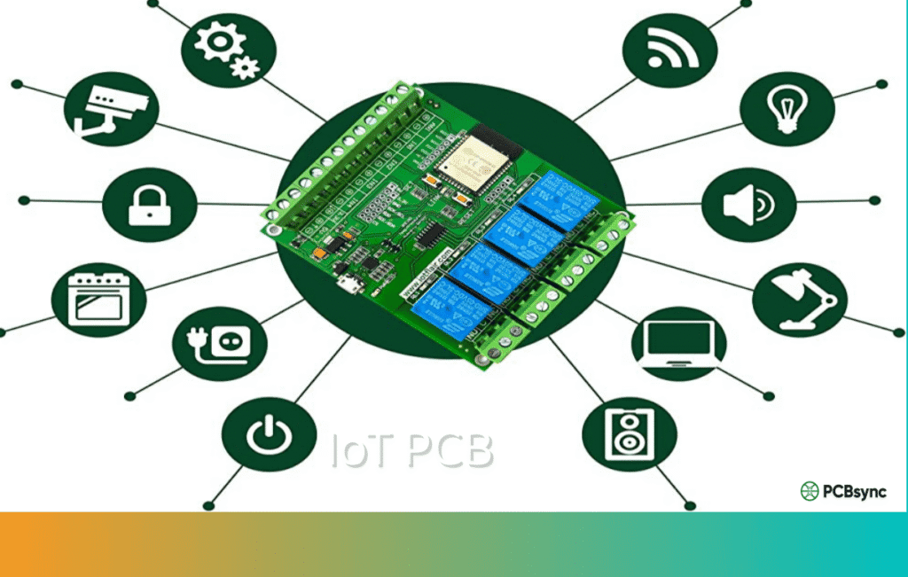
IoT PCB Design Considerations for Drones
Drone PCBs share many characteristics with other IoT PCB applications, but the combination of requirements creates unique design challenges. Let’s examine the key considerations that separate a good drone board from a great one.
Weight Optimization Strategies
Every design decision should consider weight implications. Here are proven techniques for reducing board mass without sacrificing reliability:
Reduce board thickness. Standard 1.6mm FR4 works fine for prototypes, but production boards often use 0.8mm or even 0.6mm substrates. Thinner boards flex more, so verify your design can handle the mechanical stress.
Minimize copper coverage. Use ground pours only where needed for thermal or EMI reasons. Remove unnecessary copper from inner layers. Consider cross-hatched ground planes instead of solid fills.
Cutouts and slots. Remove material where no traces or components exist. A board with strategic cutouts can weigh 10-15% less than a solid one.
Component selection. Choose smaller package sizes when current handling allows. 0402 passives instead of 0603. QFN packages instead of LQFP. Integrated modules instead of discrete circuits.
Thermal Management Techniques
High-current motor drivers, voltage regulators, and video transmitters generate substantial heat. Without proper thermal design, components overheat, reduce their lifespan, or trigger thermal shutdowns mid-flight.
Thermal vias are your primary tool for heat dissipation. Place arrays of small vias (0.3mm diameter typical) beneath hot components to conduct heat through the board. For best results, fill the vias with solder or copper to increase thermal conductivity.
Copper pours act as heat spreaders. Connect thermal pads to large copper areas on multiple layers. Inner plane layers are particularly effective because they’re protected from airflow turbulence.
Component placement affects thermal distribution. Avoid clustering heat sources together. Position hot components where they’ll receive airflow from propellers—the downdraft from motors provides significant cooling during flight.
Thermal Solution
Effectiveness
Weight Impact
Thermal vias
High
Minimal
Copper pours
Medium-High
Adds copper weight
Heat sinks
High
Significant weight
Thermal pads
Medium
Minimal
Signal Integrity for Sensor Accuracy
The IMU and barometer outputs that control flight stability require excellent signal integrity. Noise or interference on these signals translates directly into twitchy, unstable flight characteristics.
Trace length matters. Keep high-speed digital lines short. The SPI bus between the MCU and IMU should be under 10mm if possible. Longer traces act as antennas that pick up interference.
Separate analog and digital grounds. While single-point grounding is outdated for most applications, keeping analog sensor signals away from noisy digital areas remains important. Use solid ground planes but partition them mentally when placing components.
Differential pairs for high-speed signals like USB require controlled impedance routing. Most flight controller designs target 90Ω differential impedance for USB lines.
Clock signals from crystal oscillators radiate EMI. Surround crystal layouts with ground vias to contain the emissions. Keep the crystal as close to the processor as possible.
Drones experience rapid load changes. When motors spin up quickly, battery voltage droops. When motors brake, regenerative voltage spikes occur. Your power distribution must handle these transients gracefully.
Bulk capacitance on the main battery input smooths voltage fluctuations. Most designs use 2-4 low-ESR electrolytic capacitors totaling 200-1000µF, supplemented by ceramic capacitors for high-frequency filtering.
Wide power traces reduce resistive losses and voltage drops. Calculate minimum trace width based on expected current using standard formulas or online calculators. For 20A motor current, you’ll need traces wider than 5mm at 1oz copper thickness.
Separate power domains where possible. Motor power, servo power, and logic power should have distinct paths from the battery to prevent noise coupling. Star topology distribution from a central point works better than daisy-chaining.
PCB Material Selection for Drone Applications
Material choice significantly impacts your drone’s performance, weight, and cost. Understanding the tradeoffs helps you make informed decisions.
FR4: The Standard Choice
FR4 fiberglass-reinforced epoxy laminate handles most drone applications well. It’s affordable, widely available, and offers good mechanical properties. Standard FR4 has a glass transition temperature (Tg) around 130-140°C, which suffices for typical operating conditions.
For designs with higher thermal demands—integrated ESCs or high-power video transmitters—consider high-Tg FR4 (170°C or higher). The improved thermal stability prevents warping and delamination during reflow soldering and extended operation.
When RF performance matters—GPS antennas, long-range receivers, high-power video transmitters—specialized materials offer advantages over standard FR4.
Lower dielectric loss for better antenna efficiency
Consistent dielectric constant across frequency
Improved temperature stability
The downside is cost. Rogers materials cost 5-10x more than FR4, so most designs use hybrid stackups: Rogers for the antenna layer, FR4 for everything else.
Flexible and Rigid-Flex PCBs
Foldable drone arms and compact gimbal assemblies benefit from flexible circuit technology. Polyimide-based flex circuits bend repeatedly without cracking, enabling designs that would be impossible with rigid boards alone.
Rigid-flex combines stiff sections for component mounting with flexible sections for connections. This eliminates connectors (reducing weight and failure points) while allowing complex three-dimensional packaging.
The tradeoff is manufacturing complexity and cost. Rigid-flex boards typically cost 3-5x more than equivalent rigid designs.
Step-by-Step Drone PCB Design Process
Let me walk you through the workflow I follow when designing a new drone flight controller. This process applies whether you’re using KiCad, Altium Designer, or any other professional EDA tool.
Step 1: Define Requirements
Before touching schematic software, document exactly what your board needs to do:
This requirements document guides every subsequent decision. Changing fundamental requirements mid-design wastes enormous time.
Step 2: Create the Schematic
Start with power architecture—how battery voltage converts to each required rail. Then add the processor and its support circuitry (crystal, decoupling, reset, boot configuration). Connect sensors, motor outputs, and communication interfaces.
Some schematic tips from hard-won experience:
Use hierarchical sheets to organize complex designs. Group related functions together. Add generous notes explaining non-obvious design choices—future you will thank present you.
Verify component availability before finalizing the schematic. Supply chain disruptions have taught us all that “theoretically available” and “actually purchasable” differ significantly.
Step 3: Component Placement
Good placement makes routing easier and improves performance. Bad placement creates problems that no amount of routing skill can fix.
Start with the processor. Position it centrally with room for decoupling capacitors and the crystal oscillator nearby.
Place the IMU. Center of the board, away from motor outputs and switching regulators. Leave space for vibration isolation if needed.
Position connectors. Battery connector where the cable naturally routes. Motor outputs near their respective corners. Receiver and peripheral connectors on board edges for easy access.
Locate hot components. Voltage regulators and ESC drivers near board edges where airflow helps cooling.
Add test points. Include test points for critical signals—you’ll thank yourself during debugging and production testing.
Step 4: Layer Stackup Selection
Layer count depends on design complexity. Simple flight controllers work with 4 layers. Integrated designs with ESCs typically need 6 layers. The most complex AIO boards might require 8 or more.
A typical 4-layer drone PCB stackup:
Layer
Function
Copper Weight
Top
Signal + Power
1oz or 2oz
Inner 1
Ground plane
1oz
Inner 2
Power plane
1oz
Bottom
Signal + Power
1oz or 2oz
This arrangement provides solid reference planes for signals while allowing power distribution on outer layers where thick copper is easier to manufacture.
Step 5: Routing Strategy
Route critical signals first. USB differential pairs, crystal oscillator traces, and high-speed sensor buses demand attention before general routing. These signals need controlled impedance and length matching.
Handle power next. Motor phase outputs need the widest traces your layer stack allows. Power rails should flow smoothly without bottlenecks.
Complete general routing. Fill in remaining connections. Use the autorouter if you like for initial passes, but expect to manually optimize the results.
Pour ground copper. After routing completes, add ground fills to unused areas. This improves thermal performance and reduces EMI.
Step 6: Design Rule Check and Verification
Run DRC religiously. Fix all errors. Review all warnings. Then run it again.
Beyond automated checks, manually verify:
Antenna trace impedances match specifications
High-current paths have adequate copper
Thermal vias connect hot components to heat-spreading layers
No signals cross splits in reference planes
Step 7: Generate Manufacturing Files
Export Gerbers, drill files, and assembly drawings. Include a fabrication note specifying critical parameters:
Controlled impedance requirements
Copper weights per layer
Surface finish (ENIG for fine-pitch components)
Special materials if using Rogers or flex
Drone PCB Manufacturing Process
Understanding how your board gets manufactured helps you design for manufacturability and avoid costly mistakes.
Fabrication Steps
Inner layer imaging – Photoresist applied, UV exposed through artwork, developed to reveal copper patterns
Etching – Unwanted copper removed chemically
Lamination – Layers pressed together with prepreg adhesive under heat and pressure
Drilling – Mechanical or laser drilling creates via holes
Plating – Copper electroplated into holes to create electrical connections
Outer layer processing – Similar imaging and etching for outer layers
Solder mask – Protective coating applied over copper, openings for pads
Surface finish – HASL, ENIG, or other finish applied to exposed copper
Silkscreen – Reference designators and markings printed
X-ray inspection reveals hidden defects in BGA packages and buried vias.
Electrical testing verifies continuity and isolation on every board.
Functional testing powers up boards and validates firmware operation before shipping.
For safety-critical drone applications, specify IPC Class 2 or Class 3 inspection standards to ensure higher reliability.
PCB Design Software and Tools
Several capable tools exist for drone PCB design, ranging from free open-source options to professional commercial packages.
Recommended Design Software
Software
Cost
Best For
KiCad
Free
Hobbyists, open-source projects
Altium Designer
$$$$
Professional complex designs
Eagle
$$$
Mid-complexity boards
EasyEDA
Free/$
Quick prototypes
OrCAD
$$$$
Enterprise workflows
KiCad has improved dramatically and handles most drone designs capably. Its component libraries grow constantly, and the active community provides support. For complex AIO boards with integrated ESCs, Altium’s more sophisticated constraint management and simulation tools justify the cost.
Useful Resources and Downloads
Here are resources I reference regularly:
Component Datasheets and Reference Designs
STMicroelectronics: https://www.st.com (STM32 processors, motor drivers)
Before trusting your design with expensive components or flight testing, thorough verification prevents costly mistakes.
Bench Testing Protocol
Power up the board incrementally. First apply 3.3V to logic sections only, verifying current draw matches expectations. Then enable 5V peripherals. Finally connect battery voltage to motor circuits.
Monitor temperatures during extended operation. Use a thermal camera or contact thermometer to identify hot spots. Components running above 60°C during bench testing will likely overheat during actual flight when airflow patterns differ.
Test all communication interfaces systematically. Verify USB enumeration, UART baud rates, SPI sensor communication, and receiver binding. Problems found on the bench are far easier to debug than those discovered after assembly into a frame.
Flight Testing Considerations
Initial flight tests should occur in controlled environments with the drone tethered or constrained. This allows testing motor response and stabilization without risking uncontrolled flight.
Monitor telemetry closely during early flights. Watch for:
Voltage sag under load
Temperature increases
IMU noise levels
Control loop performance
Document all test results. This data proves invaluable when troubleshooting issues that appear later or when iterating to improved designs.
Common Design Mistakes and How to Avoid Them
Learning from others’ mistakes saves debugging time. Here are issues I’ve encountered repeatedly in drone PCB reviews:
Insufficient motor trace width. Calculate current capacity properly. That 1mm trace carrying 30A will overheat and potentially burn.
IMU too close to switching regulators. The magnetic fields from inductor currents corrupt gyroscope readings. Keep at least 10mm separation.
Missing bulk capacitors on battery input. Without adequate capacitance, motor startup currents cause processor brownouts.
Antenna traces crossing ground plane gaps. This destroys impedance and reduces range dramatically.
No thermal relief on ground plane connections. Large ground pours connected solidly to pads make hand soldering nearly impossible.
Forgetting programming/debug connectors. That first prototype needs debugging access. Add SWD pads even if you remove them from production versions.
FAQs About Drone PCB Design
What’s the best PCB layer count for a drone flight controller?
For standalone flight controllers, 4 layers work well. The standard stackup uses top and bottom signal layers with inner ground and power planes. This provides good signal integrity at reasonable cost. When integrating ESCs (electronic speed controllers), 6 layers become preferable—the additional layers help manage the high currents and thermal loads. Complex all-in-one boards combining FC, ESC, VTX, and PDB might require 8 layers for proper routing and thermal management.
How do I reduce EMI in my drone PCB design?
EMI reduction starts at placement. Separate noisy circuits (switching regulators, motor drivers) from sensitive ones (IMU, GPS, receivers) by maximum practical distance. Use solid ground planes beneath all signal traces to provide controlled return current paths. Add ground guard rings around sensitive components with via stitching connecting to inner ground planes. Filter power supplies to sensitive circuits with LC networks. For especially troublesome EMI sources, consider metal shielding cans over the offending components.
Which PCB material should I use for drone GPS antennas?
Standard FR4 works adequately for passive GPS antennas in short-range applications. For commercial drones requiring consistent positioning accuracy, Rogers RO4350B or similar low-loss materials improve antenna efficiency and reception sensitivity. The stable dielectric constant of Rogers materials ensures the antenna’s tuned frequency doesn’t shift with temperature changes—important when transitioning between cold high-altitude conditions and warm ground-level operation. Many designs use hybrid stackups: Rogers for the antenna layer, FR4 for the rest to balance cost and performance.
How do I design for vibration in drone PCBs?
Mechanical vibration from motors causes several problems: accelerometer saturation, solder joint fatigue, and connector wear. Component-level solutions include soft-mounting the IMU on rubber standoffs or foam pads to mechanically isolate it from frame vibrations. Board-level approaches use thicker substrates for rigidity and avoid long unsupported spans that can flex. Add mounting holes with grommets rather than direct screw contact. For connectors, choose types rated for vibration (JST-SH with locking tabs, for example) rather than friction-fit types that work loose.
Can I design my own drone PCB without professional experience?
Absolutely, though expect a learning curve. Start with simpler designs—a basic flight controller using reference designs from Betaflight or similar projects. KiCad provides capable free software, and numerous tutorials cover drone-specific design. Order prototype boards from budget manufacturers like JLCPCB to test your work. Join communities like RCGroups, Oscar Liang’s blog comments, and various Discord servers where experienced designers answer questions. Most importantly, expect early designs to require revision. Treat prototypes as learning experiences, and your skills will develop rapidly.
Future Trends in Drone IoT PCB Technology
The drone industry evolves rapidly, and PCB technology follows suit. Understanding emerging trends helps you design boards that remain relevant as the market advances.
Higher integration continues driving AIO board development. Single-chip solutions combining flight controllers, ESCs, and power management reduce component counts and simplify manufacturing. Expect this trend to accelerate as silicon vendors recognize the drone market’s growth potential.
Advanced materials are becoming more accessible. High-frequency laminates, once prohibitively expensive, now appear in mid-range commercial designs. Metal-core PCBs for improved thermal management and embedded component technology for reduced size will see broader adoption.
AI-enhanced design tools are beginning to automate routine tasks like component placement optimization and thermal analysis. While not yet replacing experienced designers, these tools accelerate iteration cycles and catch potential issues earlier.
Miniaturization pushes toward smaller component packages and finer PCB features. HDI (High-Density Interconnect) techniques including microvias and buried vias enable denser layouts for increasingly capable tiny drones.
Regulatory compliance grows more complex as drone applications expand. Expect increasing requirements for EMC certification, particularly in commercial and industrial markets. Designing for compliance from the start saves expensive redesigns later.
Conclusion
Designing PCBs for drones combines the constraints of IoT PCB development—compact size, low power, wireless connectivity—with additional demands for weight optimization, vibration resistance, and high-current handling. Success requires understanding how each design decision impacts flight performance.
The key takeaways from years of drone board development:
Start with clear requirements and don’t deviate without good reason. Place components thoughtfully before routing—you can’t fix bad placement with clever traces. Respect the physics of high-current paths and sensitive sensors sharing the same board. Test prototypes thoroughly before committing to production quantities.
Modern design tools and affordable prototype manufacturing make custom drone PCB development accessible to hobbyists and professionals alike. The open-source flight controller community provides excellent references to learn from. Whether you’re designing your first quadcopter board or optimizing a commercial UAV platform, the principles outlined here apply.
The field continues evolving rapidly. New processor families, improved sensors, and advanced manufacturing techniques create opportunities for better drone designs every year. Stay curious, keep learning, and happy flying.
Inquire: Call 0086-755-23203480, or reach out via the form below/your sales contact to discuss our design, manufacturing, and assembly capabilities.
Quote: Email your PCB files to Sales@pcbsync.com (Preferred for large files) or submit online. We will contact you promptly. Please ensure your email is correct.
Notes: For PCB fabrication, we require PCB design file in Gerber RS-274X format (most preferred), *.PCB/DDB (Protel, inform your program version) format or *.BRD (Eagle) format. For PCB assembly, we require PCB design file in above mentioned format, drilling file and BOM. Click to download BOM template To avoid file missing, please include all files into one folder and compress it into .zip or .rar format.


