Inquire: Call 0086-755-23203480, or reach out via the form below/your sales contact to discuss our design, manufacturing, and assembly capabilities.
Quote: Email your PCB files to Sales@pcbsync.com (Preferred for large files) or submit online. We will contact you promptly. Please ensure your email is correct.
Notes: For PCB fabrication, we require PCB design file in Gerber RS-274X format (most preferred), *.PCB/DDB (Protel, inform your program version) format or *.BRD (Eagle) format. For PCB assembly, we require PCB design file in above mentioned format, drilling file and BOM. Click to download BOM template To avoid file missing, please include all files into one folder and compress it into .zip or .rar format.
After 15 years working in PCB manufacturing and quality control, I’ve seen firsthand how a single insulation failure can turn into a nightmare. One moment you have a batch of boards ready to ship, and the next you’re dealing with catastrophic field failures, unhappy customers, and expensive recalls. This is exactly why the dielectric voltage test has become one of the most critical quality assurance steps in modern PCB production.
Whether you’re designing high-voltage power supplies, automotive electronics, or medical devices, understanding the dielectric voltage test isn’t optional—it’s essential. In this guide, I’ll walk you through everything you need to know about this crucial test, from basic principles to advanced implementation strategies.
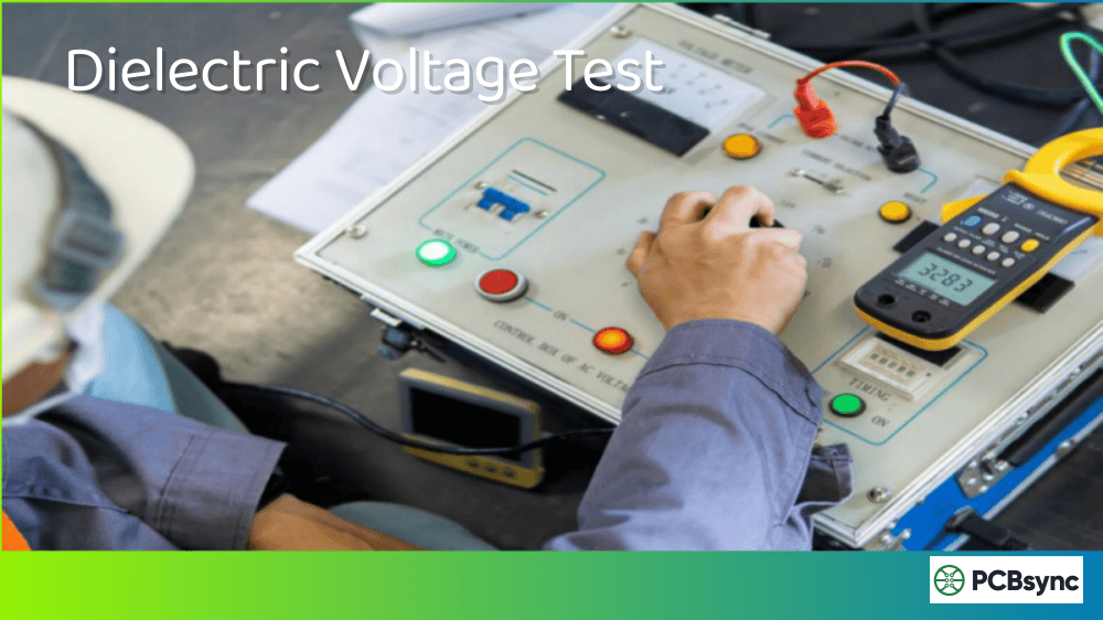
The dielectric voltage test, commonly called the HiPot test (short for High Potential), is an electrical safety test that verifies the integrity of insulation in printed circuit boards. During this test, we apply a voltage significantly higher than the board’s normal operating voltage between mutually isolated conductors to prove that the PCB can safely handle its rated voltage plus any momentary overvoltages from switching, surges, or similar phenomena.
Think of it this way: if your PCB operates at 120V, you want to be absolutely certain that the insulation won’t break down during a voltage spike. The dielectric voltage test stresses the insulation beyond normal operating conditions to give you that confidence.
According to IPC-TM-650 standards, this test isn’t designed to cause insulation breakdown. Rather, it determines whether the insulating materials and conductor spacings are adequate for safe operation. When a board fails this test, it typically indicates manufacturing defects, material problems, or design issues that need addressing before the product reaches end users.
Why Dielectric Voltage Testing Matters in PCB Manufacturing
In my experience, manufacturers who skip or shortcut dielectric voltage testing eventually pay the price. Here’s why this test is non-negotiable for quality PCB production:
Safety Assurance: The primary purpose is protecting end users from electrical shock. A breakdown in insulation between primary circuits and grounded/accessible parts can be fatal.
Regulatory Compliance: Safety agencies worldwide, including UL, IEC, and CE marking bodies, mandate dielectric withstanding voltage tests for most electrical products. Without passing this test, you simply cannot sell your product in major markets.
Defect Detection: The dielectric voltage test catches problems that other tests miss: voids in laminate materials, conductive contamination, inadequate conductor spacing, damaged insulation, and manufacturing defects like incomplete etching or copper slivers.
Quality Verification: For high-reliability applications in aerospace, medical, automotive, and military sectors, this test provides documented proof that your boards meet stringent insulation requirements.
Cost Savings: Finding insulation problems during manufacturing costs a fraction of what field failures cost. A $0.50 test can prevent a $50,000 recall.
Dielectric Voltage Test vs. Other PCB Electrical Tests
Understanding where the dielectric voltage test fits among other electrical tests helps you build a comprehensive quality strategy. Here’s how these tests compare:
Test Type
What It Measures
Voltage Level
Destructive?
Primary Use
Dielectric Voltage Test (HiPot)
Insulation integrity under stress
500V – 5kV+
No (when done correctly)
Safety verification
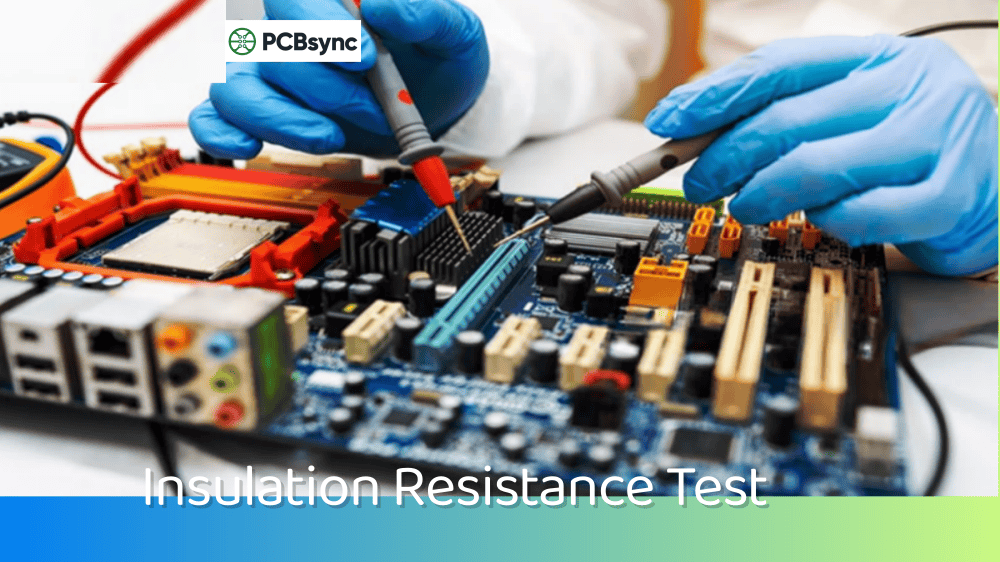
Insulation Resistance Test
Resistance of insulating materials
100V – 1000V DC
No
Material quality check
Continuity Test
Circuit path connectivity
Low voltage
No
Manufacturing verification
Dielectric Breakdown Test
Maximum voltage before failure
Increasing until failure
Yes
Material characterization
Flying Probe Test
Opens and shorts
Low voltage
No
Circuit verification
The dielectric voltage test occupies a unique position—it applies enough stress to find real problems without destroying good boards. The insulation resistance test uses lower voltages and measures the actual resistance value, while the dielectric voltage test pushes the insulation to verify it can handle worst-case voltage conditions.
IPC Standards for Dielectric Voltage Testing
The PCB industry relies on several IPC standards to guide dielectric voltage testing. Understanding these standards is crucial for setting up compliant test procedures.
IPC-TM-650 2.5.7: This is the foundational test method for dielectric withstanding voltage on PCBs. It specifies two main test conditions:
Parameter
Condition A
Condition B
Test Voltage
500V AC or 750V DC
1000V AC or 1500V DC
Ramp Rate
100V/second
100V/second
Dwell Time
60 seconds
60 seconds
Application
Standard boards
High-reliability applications
IPC-TM-650 2.5.7.2: Specifically addresses thin dielectric layers for embedded passive devices, with voltage ramp rates of 5% of peak voltage per second for qualification testing.
IPC-6012: Qualification and Performance Specification for Rigid Printed Boards includes dielectric withstanding voltage requirements as part of the overall board qualification.
IPC-9252A: Provides guidelines for electrical testing, including parameters for HiPot testing between power and ground layers.
IPC-2221: The generic standard on printed board design includes minimum spacing requirements that directly relate to dielectric voltage capabilities.
When setting up your test parameters, always check the procurement documents or master drawing first—customer requirements take precedence over standard IPC conditions.
How to Perform a Dielectric Voltage Test: Step-by-Step Procedure
After setting up hundreds of dielectric voltage test procedures, I’ve developed a reliable workflow. Here’s how to perform this test correctly:
Pre-Test Preparation
Before applying any voltage, proper preparation prevents false failures and ensures accurate results:
1. Condition the Test Specimens: For qualification testing, specimens should be conditioned at 23°C ± 3°C and 50% ± 10% relative humidity for 24 hours. This standardizes moisture content, which significantly affects insulation properties.
2. Inspect the Board: Visually check for obvious defects, contamination, or damage. Boards with visible problems will likely fail anyway, so why stress them unnecessarily?
3. Verify Test Equipment: Ensure your HiPot tester meets specifications—voltage accuracy within 5%, proper leakage current measurement capability, and adjustable ramp and dwell settings.
4. Establish Safety Barriers: The limited approach boundary at 1000V is 5 feet. Place barriers to prevent unqualified personnel from approaching test areas.
Test Execution
Step 1: Connect positive leads from all nets being tested together, and connect negative leads separately. For testing between power and ground layers, connect all VCC nets to one lead and all GND nets to the other.
Step 2: Attach the leads of the HiPot tester to the prepared test points. Ensure connections are secure and won’t arc during testing.
Step 3: Program the tester with appropriate parameters:
Peak voltage as specified (typically 500V-1500V AC or equivalent DC)
Ramp rate of 100V per second (or 5% of peak voltage per second for thin dielectrics)
Dwell time of 60 seconds (or as specified)
Current threshold appropriate for your board design
Step 4: Raise the test voltage from zero to the specified value at the programmed ramp rate.
Step 5: Maintain the test voltage for the full dwell period while monitoring for any indication of flashover, sparkover, or breakdown.
Step 6: After the dwell period, reduce voltage to zero and disconnect the test specimen.
Post-Test Evaluation
Record whether the specimen exhibited any of the following:
Flashover (visible arc through air)
Sparkover (partial discharge)
Breakdown (insulation failure)
Excessive leakage current
A passing result means no breakdown occurred and leakage current stayed below threshold during the entire test.
AC vs. DC Dielectric Voltage Testing: Which Should You Use?
One of the most common questions I get is whether to use AC or DC voltage for dielectric testing. Both have their place, and understanding the differences helps you choose correctly.
AC Dielectric Voltage Test
How it works: An alternating voltage (typically at 50/60 Hz) is applied, stressing the insulation at both positive and negative polarities during each cycle.
Advantages:
Tests both voltage polarities, simulating actual AC operating conditions
No need to discharge the DUT after testing
Longer ramp time usually not required
More accepted by safety regulatory agencies for AC-powered products
Can detect certain types of defects more quickly
Disadvantages:
Capacitive current through the insulation can cause false failures
Total current includes both real (leakage) and reactive (capacitive) components
Y-capacitors in circuits can trip current thresholds
Higher output current capacity required from test equipment
DC Dielectric Voltage Test
How it works: A steady DC voltage is ramped up and held, with only real leakage current flowing after initial charging current decays.
Advantages:
More accurate leakage current readings (measures only real current)
Lower trip current settings possible, catching marginal insulation
Can detect certain defect types (voids, inclusions, contamination) more effectively
Penetrates deeper into insulation for more thorough testing
Y-capacitors don’t cause false failures
Disadvantages:
Tests only one polarity
Requires careful voltage ramping to avoid charging current triggering failures
DUT must be safely discharged after testing
Longer test times needed for capacitive loads
Higher voltage required (typically 1.414× AC voltage) for equivalent stress
Voltage Conversion
When substituting DC for AC testing, use this formula:
DC Test Voltage = AC Test Voltage × 1.414
For example: A 1500V AC test would become 2121V DC to provide equivalent peak voltage stress.
My Recommendation
For most PCB applications operating on AC power, use AC dielectric voltage testing—it better simulates actual operating conditions and is more widely accepted by certification bodies. Use DC testing when:
The product operates on DC power
You need precise leakage current measurements
The board has large Y-capacitors that would cause AC test failures
You’re testing cables or components where DC better detects certain defects
Common Dielectric Voltage Test Failures and Troubleshooting
When boards fail dielectric voltage testing, quick and accurate troubleshooting saves time and money. Here are the most common failure modes I’ve encountered and how to address them:
Manufacturing Defects
Incomplete Etching: Microscopic tracks of copper left between pads or traces can cause arcing. These are often invisible at 7× magnification but fail under high voltage. Solution: Review etching process parameters and improve AOI detection thresholds.
Copper Slivers: Overetching can create tiny copper or tin-lead slivers that bridge power and ground. These conductive particles may only make contact under test voltage stress. Solution: Implement better process controls and post-etch cleaning.
Voids in Laminate: Air pockets in the dielectric material have much lower breakdown voltage than the surrounding material. Since air breaks down at roughly 1000V/mm compared to 10,000V/mm for solid insulation, voids create weak points. Solution: Improve lamination processes and consider vacuum lamination for critical boards.
Contamination: Conductive contaminants on the board surface reduce surface insulation resistance. Flux residue, fingerprints, and environmental contamination are common culprits. Solution: Improve cleaning processes and handling procedures.
Design-Related Issues
Inadequate Spacing: If conductor spacing is too close for the operating voltage, the board will eventually fail under test or in service. Solution: Review design against IPC-2221 spacing requirements and increase clearances.
Thin Dielectric Layers: As PCBs get denser with more layers, dielectric thickness decreases. This reduces the voltage withstand capability. Solution: Verify layer stackup provides adequate dielectric thickness for the voltage class.
Test-Related Issues
False Failures from Capacitance: High-capacitance circuits can draw enough charging current to trip the test threshold, especially with AC testing. Solution: Increase trip current setting, use DC testing, or temporarily disconnect large capacitors for type testing.
Environmental Conditions: Humidity affects insulation resistance. Testing in high-humidity conditions may cause failures that wouldn’t occur in normal use. Solution: Condition specimens properly and control test environment.
Damaged Insulation from Previous Tests: Repeatedly testing failed boards can make defects worse. Each arc creates additional damage. Solution: Investigate failures promptly rather than retesting repeatedly.
Troubleshooting Decision Tree
Symptom
Likely Cause
Investigation Method
Visible arc during test
Inadequate spacing or contamination
Visual inspection under magnification
Gradual current rise
Material degradation or moisture
Check conditioning, review material spec
Immediate trip at low voltage
Gross defect or contamination
Visual inspection, cleaning, retest
Intermittent failures
Marginal spacing or loose contamination
Review design, improve cleaning
Consistent failures at specific voltage
Design limitation
Review spacing vs. voltage requirements
Dielectric Voltage Testing in SMT Assembly
While dielectric voltage testing is primarily associated with bare board manufacturing, it plays an important role in assembled PCB quality as well. Here’s how this test fits into the SMT assembly workflow:
When to Test
Bare Board Stage: Most dielectric voltage testing happens before assembly. This catches board-level defects before expensive components are mounted.
Post-Assembly Testing: For high-reliability applications (medical, aerospace, automotive), additional HiPot testing after assembly verifies that the assembly process didn’t damage insulation.
Incoming Inspection: Some assembly houses perform HiPot testing on incoming bare boards to verify supplier quality.
Integration with Other Tests
A comprehensive SMT assembly test strategy combines multiple methods:
Sensitive Components: Some components (especially ICs) can be damaged by high voltage. Test programs must account for these by either excluding sensitive nets or using voltage levels safe for all components.
Capacitor Effects: Assembled boards with capacitors will draw significant charging current. Adjust test parameters accordingly.
Discharge Requirements: After DC HiPot testing, ensure adequate discharge time before handling to prevent shock hazards.
Equipment for Dielectric Voltage Testing
Selecting the right test equipment ensures accurate results and efficient testing. Here’s what to consider:
Key Equipment Specifications
Feature
Importance
Typical Range
Output Voltage
Must exceed test requirements
500V – 5kV+
Voltage Type
AC, DC, or both as needed
50/60 Hz AC or DC
Leakage Current Measurement
Critical for marginal defect detection
µA to mA range
Current Threshold Setting
Must be adjustable
0.1mA – 100mA
Ramp Rate Control
Required for proper testing
100V/s typical
Dwell Timer
Ensures consistent test duration
1-60 seconds
Safety Features
Protects operators
Interlock, auto-discharge, indicators
Testing Methods
Manual Probing: An operator manually moves probes between test points. Suitable for prototypes and low-volume testing but slow and operator-dependent.
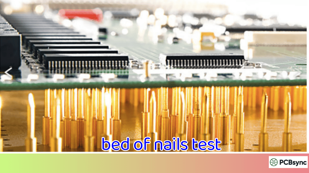
Fixture Testing: A dedicated test fixture with pogo pins contacts all test points simultaneously. The tester automatically sequences through programmed tests. Better for medium-volume production.
Flying Probe: Automated probes move to test points under computer control. Excellent flexibility without fixture costs. Good for mixed production environments.
Grid Test Systems: High-volume production systems that test thousands of points simultaneously. Highest throughput but highest fixture costs.
Equipment Recommendations
For prototype and low-volume work, a basic benchtop HiPot tester with manual probes works well. Look for units offering both AC and DC capability with adjustable current thresholds.
For production environments, integrate HiPot testing into your electrical test system. Flying probe machines can be programmed for HiPot sequences, and many grid test systems offer HiPot options.
Useful Resources and Standards References
Here are the key documents and resources for implementing dielectric voltage testing:
UL Standards: www.ul.com (Safety certification requirements)
FAQs About Dielectric Voltage Testing
What voltage should I use for dielectric voltage testing?
The test voltage depends on your product’s operating voltage and applicable safety standards. A common rule of thumb is 2× operating voltage + 1000V. For a 120V AC product, this gives approximately 1340V, typically rounded to 1500V AC. However, always check the specific safety standard for your product category—requirements vary significantly between consumer electronics, medical devices, and industrial equipment.
Can repeated dielectric voltage testing damage good boards?
When performed correctly at specified voltage levels and durations, dielectric voltage testing shouldn’t damage properly manufactured boards. The test voltage is designed to stress insulation without causing breakdown in conforming products. However, repeatedly testing failed boards can worsen existing defects. If a board fails, investigate the cause rather than retesting multiple times. For production testing, some standards allow reduced voltage (by about 10%) with shorter duration (1-2 seconds) to minimize any cumulative stress.
What’s the difference between HiPot testing and dielectric breakdown testing?
HiPot testing (dielectric withstanding voltage) applies a specified voltage to verify insulation can handle it without breakdown—it’s a pass/fail quality test. Dielectric breakdown testing increases voltage until the insulation actually fails, determining the maximum voltage the material can withstand. Breakdown testing is destructive and used for material characterization, not production testing. Think of HiPot as checking that insulation exceeds requirements, while breakdown testing finds the actual limit.
How do I handle boards with high capacitance during dielectric voltage testing?
High-capacitance boards, especially those with large Y-capacitors, can draw significant charging or reactive current that may trip test thresholds. Several approaches work: Use DC testing (capacitors block DC after initial charging); increase the current trip threshold (ensure it’s still below breakdown levels); remove Y-capacitors during type testing (not practical for production); or use a HiPot tester with higher current capability. Document your approach and ensure it’s approved by the relevant certification body.
Should dielectric voltage testing be done before or after SMT assembly?
Both approaches have merit. Testing bare boards catches insulation defects before adding expensive components, making it the most common approach and the most cost-effective. However, for high-reliability applications (medical, aerospace, automotive), post-assembly HiPot testing provides additional assurance that the assembly process didn’t damage insulation. Many manufacturers test bare boards from suppliers and perform additional testing on assembled units for critical applications. Consider the cost-risk tradeoff for your specific application.
Best Practices for Implementing Dielectric Voltage Testing
Based on years of hands-on experience, here are the best practices that separate successful dielectric voltage testing programs from problematic ones:
Document Everything: Create detailed test procedures that specify voltage levels, ramp rates, dwell times, current thresholds, and acceptance criteria. When someone asks why you chose 1500V instead of 1000V, you should have a documented answer.
Train Your Operators: High voltage testing is inherently dangerous. Ensure all personnel understand both the technical aspects and safety requirements. Certification training is worth the investment.
Calibrate Regularly: Your HiPot tester’s accuracy directly affects test validity. Follow manufacturer recommendations for calibration intervals, and keep calibration records for audit purposes.
Control Your Environment: Temperature and humidity affect insulation resistance. Maintain consistent environmental conditions in your test area, especially for qualification testing.
Track Your Data: Record not just pass/fail results but actual leakage current readings. Trending this data can reveal process drift before it causes failures.
Integrate with Your Quality System: Dielectric voltage testing should connect to your broader quality management system. Failed boards need documented disposition—repair, scrap, or engineering review.
Conclusion: Making Dielectric Voltage Testing Work for You
The dielectric voltage test isn’t just another quality checkbox—it’s a fundamental safeguard that protects your customers and your business. Throughout my career, I’ve seen companies that treat this test as a formality eventually face costly recalls, while those who invest in proper dielectric voltage testing consistently deliver reliable products.
Here’s what I want you to take away from this guide:
Start with the right standards: Whether you’re following IPC-TM-650, IEC requirements, or customer specifications, know what you’re testing against before you begin.
Choose appropriate test parameters: Match your voltage, ramp rate, and dwell time to your product’s requirements. Don’t over-test (which risks damaging good boards) or under-test (which risks shipping defective products).
Understand what failures tell you: Every failed dielectric voltage test is an opportunity to improve your process. Whether it’s a design issue, manufacturing defect, or contamination problem, root cause analysis prevents future failures.
Integrate testing into your workflow: The dielectric voltage test works best as part of a comprehensive quality strategy, not as an isolated check.
If you’re just starting with dielectric voltage testing or looking to improve your existing process, focus on getting the fundamentals right. Proper equipment, trained operators, documented procedures, and consistent execution will serve you far better than the most sophisticated test system operated incorrectly.
The boards that pass your dielectric voltage test today will be powering products in the field for years to come. Make sure they deserve that trust.
Inquire: Call 0086-755-23203480, or reach out via the form below/your sales contact to discuss our design, manufacturing, and assembly capabilities.
Quote: Email your PCB files to Sales@pcbsync.com (Preferred for large files) or submit online. We will contact you promptly. Please ensure your email is correct.
Notes: For PCB fabrication, we require PCB design file in Gerber RS-274X format (most preferred), *.PCB/DDB (Protel, inform your program version) format or *.BRD (Eagle) format. For PCB assembly, we require PCB design file in above mentioned format, drilling file and BOM. Click to download BOM template To avoid file missing, please include all files into one folder and compress it into .zip or .rar format.


