Inquire: Call 0086-755-23203480, or reach out via the form below/your sales contact to discuss our design, manufacturing, and assembly capabilities.
Quote: Email your PCB files to Sales@pcbsync.com (Preferred for large files) or submit online. We will contact you promptly. Please ensure your email is correct.
Notes: For PCB fabrication, we require PCB design file in Gerber RS-274X format (most preferred), *.PCB/DDB (Protel, inform your program version) format or *.BRD (Eagle) format. For PCB assembly, we require PCB design file in above mentioned format, drilling file and BOM. Click to download BOM template To avoid file missing, please include all files into one folder and compress it into .zip or .rar format.
Design for Environment (DFE): Sustainable PCB Design Practices
When I started designing circuit boards twenty years ago, environmental considerations were an afterthought. Today, they’re increasingly becoming a design requirement. With 62 million tonnes of e-waste generated globally in 2022 and PCBs making up 42% of that waste by weight, our industry faces a sustainability reckoning. DFE design environment PCB methodology has transformed from a nice-to-have into a business necessity.
Design for Environment represents a systematic approach to minimizing the environmental impact of products throughout their entire lifecycle—from raw material extraction through manufacturing, use, and end-of-life disposal. For PCB engineers, this means rethinking material choices, manufacturing processes, and designing for recyclability from day one.
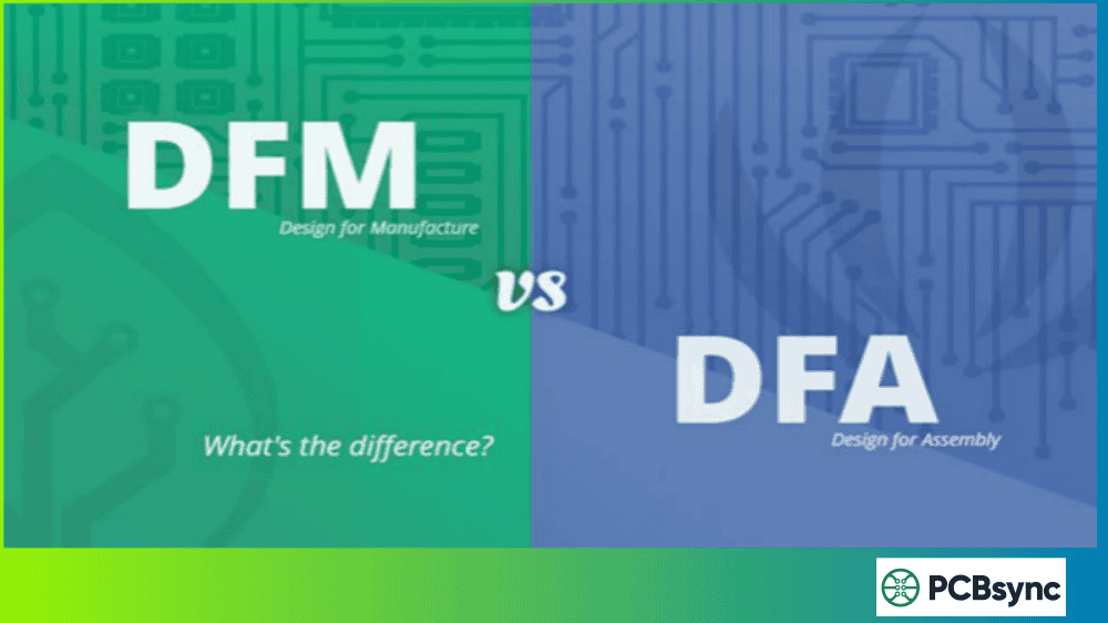
Design for Environment (DFE) is part of the broader Design for Excellence (DFX) methodology, sitting alongside Design for Manufacturing (DFM), Design for Cost (DFC), and Design for Reliability (DFR). While those methodologies focus on production efficiency, cost, and longevity, DFE design environment PCB practices specifically target reducing environmental harm at every stage.
The core principle is simple: consider environmental impact during design, when changes are cheapest and most effective. A material substitution during schematic capture costs almost nothing. The same change after production tooling? Potentially hundreds of thousands in redesign expenses.
Regulatory Compliance: Avoiding RoHS, REACH, and WEEE penalties that can reach millions in fines and market access restrictions
Cost Reduction: Less hazardous material handling, simplified waste disposal, and reduced liability exposure
Market Differentiation: Consumer and B2B customers increasingly demand sustainable products
Supply Chain Resilience: Reducing dependence on conflict minerals and supply-constrained materials
Key Environmental Regulations for PCB Design
Understanding regulatory requirements forms the foundation of any DFE design environment PCB strategy. Here are the primary directives affecting our industry:
Regulation
Scope
Key Requirements
RoHS 3
EU/Global
Restricts 10 hazardous substances including lead, mercury, cadmium, hexavalent chromium
WEEE
EU
Mandates producer responsibility for collection, recycling, and proper disposal of e-waste
REACH
EU
Requires registration and authorization of chemical substances, including Substances of Very High Concern (SVHC)
China RoHS
China
Similar to EU RoHS with additional labeling requirements
California Prop 65
USA
Requires warning labels for products containing harmful chemicals
RoHS Compliance Essentials
The Restriction of Hazardous Substances directive restricts these substances in electrical equipment:
Substance
Maximum Concentration
Lead (Pb)
0.1% (1000 ppm)
Mercury (Hg)
0.1% (1000 ppm)
Cadmium (Cd)
0.01% (100 ppm)
Hexavalent Chromium (Cr6+)
0.1% (1000 ppm)
Polybrominated Biphenyls (PBB)
0.1% (1000 ppm)
Polybrominated Diphenyl Ethers (PBDE)
0.1% (1000 ppm)
Bis(2-ethylhexyl) phthalate (DEHP)
0.1% (1000 ppm)
Benzyl butyl phthalate (BBP)
0.1% (1000 ppm)
Dibutyl phthalate (DBP)
0.1% (1000 ppm)
Diisobutyl phthalate (DIBP)
0.1% (1000 ppm)
For practical compliance, always request material declarations from suppliers and verify RoHS certification for all components before committing to a design.
Sustainable Material Selection for PCBs
Material selection represents the highest-impact opportunity in DFE design environment PCB implementation. The choices made during schematic and layout phases determine the environmental footprint for the product’s entire lifecycle.
Lead-Free Surface Finishes
The transition from leaded HASL to lead-free alternatives represents one of the most significant DFE achievements in our industry:
Surface Finish
Environmental Impact
Performance Notes
Lead-Free HASL
Good (eliminates lead)
Higher processing temperature, good solderability
ENIG
Better (no lead or tin)
Excellent planarity, RoHS compliant, recyclable
OSP
Best (organic, minimal chemicals)
Short shelf life, single reflow capability
Immersion Silver
Better (lead-free)
Good solderability, may tarnish
Immersion Tin
Good (lead-free)
Whisker concerns in some applications
For most applications, I recommend ENIG or OSP as the default choice. ENIG provides excellent long-term reliability and supports WEEE recycling goals since nickel and gold don’t complicate the recycling process.
Halogen-Free Laminates
Traditional FR-4 contains brominated flame retardants that release toxic dioxins when incinerated. Halogen-free alternatives use phosphorus-based flame retardants that are significantly less harmful.
Per IEC 61249-2-21, halogen-free materials must contain:
Chlorine below 0.09% (900 ppm)
Bromine below 0.09% (900 ppm)
Total halogens below 0.15% (1500 ppm)
Modern halogen-free laminates offer comparable performance to traditional FR-4 with additional benefits including improved electrical insulation, better moisture resistance, and enhanced thermal stability.
Emerging Bio-Based Materials
The most exciting development in sustainable PCB materials is the emergence of biodegradable substrates. Jiva Materials’ Soluboard represents a breakthrough—a PCB substrate made from natural fibers and water-soluble polymers that dissolves in hot water, enabling easy recovery of copper and electronic components.
According to Jiva Materials, adopting Soluboard can reduce carbon emissions by 60% compared to standard FR-4, saving approximately 10.5 kg of carbon per square meter of PCB. While current bio-based materials have limitations in high-reliability applications, they’re viable for many consumer electronics applications.
Design Strategies for Environmental Sustainability
Beyond material selection, design decisions significantly impact environmental footprint:
Design for Disassembly and Recycling
Traditional PCB assembly prioritizes permanence—components are soldered firmly, adhesives secure heavy parts, and conformal coatings seal everything. While this ensures reliability, it makes end-of-life recycling extremely difficult.
DFE-conscious design considers disassembly from the start:
Use snap-fit enclosures instead of permanent adhesives where possible
Clearly mark materials with recycling codes
Avoid mixing incompatible materials that complicate recycling
Position high-value components for easier removal and recovery
Document material content for downstream recyclers
Minimize Board Size and Layer Count
Smaller boards use less material, generate less waste during manufacturing, and reduce transportation emissions. Every unnecessary layer adds laminate, copper, and processing chemicals to the environmental burden.
Before automatically adding layers, ask: can better component placement and routing optimization achieve the same functionality with fewer layers?
Component Selection for Sustainability
Component choices affect environmental impact throughout the product lifecycle:
Choose Long-Lifecycle Components: Components approaching end-of-life often trigger complete redesigns, wasting the embedded energy and materials of the original design.
Avoid Conflict Minerals: Tantalum, tin, tungsten, and gold often originate from conflict regions. Specify conflict-free sourcing or select alternative materials where possible.
Consider Energy Efficiency: Lower-power components reduce environmental impact during the use phase—often the largest contributor to lifetime carbon footprint.
While designers can’t control manufacturing directly, specifying environmentally responsible processes influences supplier behavior:
Water and Chemical Management
Traditional PCB manufacturing consumes enormous quantities of water and chemicals. Modern DFE-aligned processes include:
Closed-loop water recycling systems
Reduced-chemistry etching processes
Additive manufacturing techniques that minimize waste
Proper treatment and disposal of wastewater
Energy Efficiency in Production
PCB fabrication is energy-intensive. Environmentally responsible manufacturers invest in:
Renewable energy sources (solar, wind)
Energy-efficient HVAC and lighting systems
Optimized thermal processes to reduce energy consumption
Waste heat recovery systems
When selecting PCB manufacturing partners, request information about their environmental certifications (ISO 14001) and sustainability practices.
End-of-Life Considerations
Designing for end-of-life is perhaps the most overlooked aspect of DFE design environment PCB practice. Less than 20% of PCBs are properly recycled—the remainder ends up in landfills where synthetic polymers release toxic compounds.
PCB Recycling Process
Understanding how PCBs are recycled helps inform design decisions:
Collection and Dismantling: Products are collected and manually disassembled
Component Recovery: High-value components like ICs and connectors are removed
Hazardous Material Removal: Batteries, capacitors with hazardous electrolytes are separated
Mechanical Shredding: Boards are shredded into 1-2 cm pieces
Material Separation: Magnetic, eddy current, and density separation extract metals
Precious Metal Recovery: Copper, gold, silver, and palladium are extracted
Designs that simplify any of these steps improve recycling economics and increase the likelihood of proper disposal.
The Circular Economy Vision
The ultimate DFE goal is circularity—materials flowing continuously through production cycles rather than ending in landfills. For PCBs, this means:
Designing for easy material separation
Using materials compatible with existing recycling infrastructure
Supporting take-back programs for end-of-life products
Selecting materials with high recycled content where available
Resources for DFE Implementation
Environmental Standards and Guidelines
ISO 14001: Environmental Management Systems
ISO 14006: Guidelines for incorporating ecodesign
ISO 14062: Integrating environmental aspects into product design
IEC 61249-2-21: Halogen-free material specifications
IPC-1752: Materials Declaration Management
Regulatory Databases
EU REACH ECHA Database: echa.europa.eu – Registered substances and SVHC list
RoHS Guide: rohsguide.com – Compliance information and updates
IMERC Database: Mercury-added products reporting
Material and Supplier Resources
Conflict-Free Sourcing Initiative: Responsible mineral sourcing certification
EPEAT Registry: Environmental ratings for electronic products
Green Electronics Council: Sustainability standards and resources
Life Cycle Assessment Tools
GaBi: Comprehensive LCA software for product analysis
SimaPro: Life cycle assessment and sustainability reporting
openLCA: Open-source life cycle assessment software
Frequently Asked Questions About DFE Design Environment PCB
What is the difference between RoHS and WEEE compliance?
RoHS restricts hazardous substances used during manufacturing, focusing on what goes into products. WEEE addresses what happens to products at end-of-life, mandating producer responsibility for collection, recycling, and proper disposal. Both directives work together—RoHS ensures products don’t contain materials that complicate WEEE recycling. Compliance with both is required for products sold in the European Union.
Are halogen-free PCBs more expensive than standard FR-4?
Halogen-free laminates typically cost 10-20% more than standard FR-4 due to specialized flame retardant chemistry and lower production volumes. However, this premium is decreasing as adoption grows. Additionally, halogen-free materials can reduce total cost of ownership through simplified waste disposal, reduced regulatory compliance burden, and improved recycling economics. For many applications, the additional material cost is offset by other savings.
How does DFE affect PCB reliability and performance?
Properly implemented DFE should not compromise reliability or performance. Modern lead-free solders, halogen-free laminates, and sustainable surface finishes meet or exceed the reliability of traditional materials in most applications. Some high-reliability applications (aerospace, medical) may require additional qualification testing when transitioning to DFE-compliant materials, but mainstream applications typically see no performance difference.
Can existing PCB designs be made more environmentally sustainable?
Yes, though the degree of improvement varies. Quick wins include substituting lead-free surface finishes, specifying halogen-free solder mask, and updating component selections to RoHS-compliant alternatives. Deeper improvements like substrate material changes or design-for-disassembly modifications typically require more significant redesign effort. For new designs, implement DFE from the start; for legacy products, prioritize changes with the highest environmental impact per design effort.
What certifications should I look for in an environmentally responsible PCB manufacturer?
Key certifications include ISO 14001 (Environmental Management System), RoHS compliance documentation, and IATF 16949 for automotive applications with sustainability requirements. Additionally, look for manufacturers with transparent chemical management programs, wastewater treatment facilities, and renewable energy investments. Request documentation of their environmental policies and ask about their sustainability roadmap.
Building Environmental Awareness Into Design Culture
The most effective DFE implementation happens when environmental thinking becomes part of the design culture, not a separate compliance checkbox. This means:
Early Integration: Consider environmental impact during concept development, not after layout completion
Cross-Functional Collaboration: Include environmental compliance specialists in design reviews
Continuous Learning: Stay current with evolving regulations and sustainable material innovations
Supplier Partnership: Work with suppliers committed to environmental responsibility
The electronics industry has made remarkable progress on sustainability—lead-free soldering, halogen-free laminates, and improved recycling infrastructure are now standard. But significant work remains. PCBs still contribute millions of tonnes to the global e-waste stream annually, and most materials are lost to landfills rather than recovered.
DFE design environment PCB practices offer a path forward. By integrating environmental considerations into every design decision, we can create products that serve their intended function while minimizing harm to the planet. The engineers making these choices today are shaping the sustainability of electronics for decades to come.
The technology exists. The regulations are in place. What remains is commitment—to learn these practices, implement them consistently, and advocate for sustainable design throughout our organizations. Our industry created the e-waste problem; we have the capability and responsibility to solve it.
Inquire: Call 0086-755-23203480, or reach out via the form below/your sales contact to discuss our design, manufacturing, and assembly capabilities.
Quote: Email your PCB files to Sales@pcbsync.com (Preferred for large files) or submit online. We will contact you promptly. Please ensure your email is correct.
Notes: For PCB fabrication, we require PCB design file in Gerber RS-274X format (most preferred), *.PCB/DDB (Protel, inform your program version) format or *.BRD (Eagle) format. For PCB assembly, we require PCB design file in above mentioned format, drilling file and BOM. Click to download BOM template To avoid file missing, please include all files into one folder and compress it into .zip or .rar format.


