Inquire: Call 0086-755-23203480, or reach out via the form below/your sales contact to discuss our design, manufacturing, and assembly capabilities.
Quote: Email your PCB files to Sales@pcbsync.com (Preferred for large files) or submit online. We will contact you promptly. Please ensure your email is correct.
Notes: For PCB fabrication, we require PCB design file in Gerber RS-274X format (most preferred), *.PCB/DDB (Protel, inform your program version) format or *.BRD (Eagle) format. For PCB assembly, we require PCB design file in above mentioned format, drilling file and BOM. Click to download BOM template To avoid file missing, please include all files into one folder and compress it into .zip or .rar format.
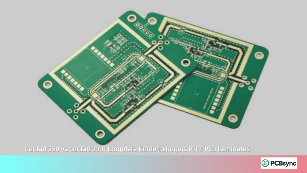
Rogers CuClad 250 vs CuClad 233: Complete Guide to Rogers PTFE PCB Laminates
If you’ve spent any time designing RF or microwave circuits, you’ve likely encountered the challenge of selecting the right laminate material. The choice between CuClad 250 and CuClad 233 is one that comes up frequently in my conversations with fellow PCB engineers, and it’s not always straightforward.
Both materials belong to Rogers Corporation’s CuClad series—woven fiberglass reinforced PTFE composites designed specifically for high-frequency applications. But understanding when to use one over the other can save you significant headaches during prototyping and production. In this guide, I’ll walk you through everything you need to know about these two laminates, drawing from real-world design experience and official specifications.
The CuClad series represents Rogers Corporation’s line of woven fiberglass/PTFE composite laminates, engineered for printed circuit board substrates and radomes in high-frequency applications. What makes these materials stand out is their cross-plied construction—alternating layers of PTFE-coated fiberglass plies oriented at 90° to each other.
This unique construction provides true electrical and mechanical isotropy in the XY plane. No other woven or non-woven fiberglass reinforced PTFE laminate makes this claim. If you’ve worked with phased array antennas, you’ll understand why this degree of isotropy matters so much.
The CuClad family includes three primary variants:
Understanding CuClad 250: Technical Specifications and Properties
CuClad 250 uses a higher fiberglass/PTFE ratio compared to its siblings, which gives it mechanical properties that approach those of conventional substrates like FR-4. This makes it particularly attractive when you need the electrical benefits of PTFE without sacrificing too much machinability.
Key Electrical Properties of CuClad 250
Here’s what you’re working with electrically:
Dielectric Constant (Dk): 2.40–2.60 at 10 GHz (available in 0.05 increments)
Dissipation Factor (Df): 0.0017 at 10 GHz
Thermal Coefficient of εr: -153 ppm/°C (-10°C to +140°C)
Volume Resistivity: 8.0 × 10⁹ MΩ-cm
Dielectric Breakdown: > 45 kV
The slightly higher Dk compared to CuClad 233 means narrower trace widths for a given impedance, but the stability of that Dk over frequency is impressive. Rogers’ data shows less than 1% variation from DC to 25 GHz.
Mechanical Advantages of CuClad 250
This is where CuClad 250 really shines:
Tensile Modulus: 725/572 kpsi (X/Y axis)
Tensile Strength: 26.0/20.5 kpsi
CTE (X/Y/Z axis): 18/19/177 ppm/°C
Flexural Modulus: 456 kpsi
Peel Strength: 14 lbs/inch (1 oz ED copper)
That low Z-axis CTE of 177 ppm/°C is significantly better than CuClad 233’s 194 ppm/°C, which translates to better plated through-hole reliability during thermal cycling.
Understanding CuClad 233: Technical Specifications and Properties
CuClad 233 occupies the middle ground in the CuClad family, using a medium fiberglass/PTFE ratio to balance lower dielectric constant with improved dissipation factor—all without sacrificing mechanical properties. It’s often my go-to recommendation for engineers who need better electrical performance than CuClad 250 but can’t justify the cost of CuClad 217.
Key Electrical Properties of CuClad 233
Dielectric Constant (Dk): 2.33 ± 0.02 at 10 GHz
Dissipation Factor (Df): 0.0013 at 10 GHz
Thermal Coefficient of εr: -161 ppm/°C
Volume Resistivity: 8.0 × 10⁸ MΩ-cm
Dielectric Breakdown: > 45 kV
The lower Df of 0.0013 (compared to CuClad 250’s 0.0017) means approximately 23% less signal loss—a significant advantage in loss-sensitive applications like satellite communications or precision instrumentation.
Mechanical Properties of CuClad 233
Tensile Modulus: 510/414 kpsi (X/Y axis)
Tensile Strength: 10.3/9.8 kpsi
CTE (X/Y/Z axis): 23/24/194 ppm/°C
Flexural Modulus: 371 kpsi
Here’s a practical note: the planar CTE of CuClad 233 (23–24 ppm/°C) closely matches aluminum (approximately 23 ppm/°C). This makes it an excellent choice for antenna structures mounted on aircraft skins and other aluminum surfaces where thermal expansion mismatch can cause cracking or delamination.
Let me put these two materials side by side so you can see the key differences at a glance. This comparison table covers the specifications that matter most for design decisions.
Property
CuClad 250
CuClad 233
Dielectric Constant (Dk)
2.40–2.60
2.33
Dissipation Factor (Df)
0.0017
0.0013
Tensile Modulus (kpsi)
725/572
510/414
CTE X/Y (ppm/°C)
18/19
23/24
CTE Z (ppm/°C)
177
194
Water Absorption (%)
0.03
0.02
Thermal Conductivity (W/m/K)
0.25
0.26
Density (g/cm³)
2.31
2.26
Flammability (UL94)
V-0
V-0
When to Choose CuClad 250 for Your RF Design
Based on my experience and the technical specifications, here are the scenarios where CuClad 250 makes the most sense:
Ideal Applications for CuClad 250
Military radar systems where dimensional stability under thermal stress is critical
Electronic countermeasures (ECM) and electronic support measures (ESM) equipment
CuClad 233 is your better choice when electrical performance takes priority over mechanical robustness. Here’s when I typically recommend it:
Ideal Applications for CuClad 233
Satellite communications where insertion loss directly impacts link budget
Low-noise amplifiers (LNAs) requiring minimal substrate loss
Precision filters and couplers with tight loss specifications
Aircraft antenna structures mounted on aluminum skins (CTE matching)
Commercial wireless infrastructure balancing cost and performance
Design Considerations for CuClad 233
Lower Dk enables wider trace widths—easier to fabricate and less sensitive to etching tolerances
The 23% lower loss tangent compounds over longer transmission line lengths
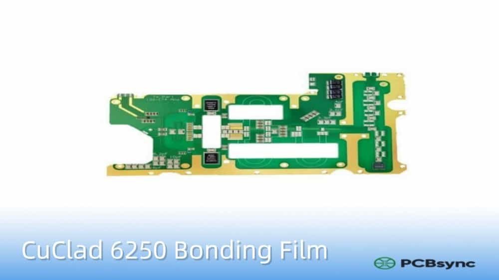
Excellent choice for hybrid stackups with CuClad 6250 or 6700 bonding films
Verify mechanical support requirements—lower modulus may need backing plates for larger panels
Fabrication Guidelines for CuClad PTFE Laminates
Working with PTFE-based materials requires some adjustments to standard FR-4 processing. Here are the key points from both Rogers’ guidelines and practical shop floor experience:
Surface Preparation for CuClad PCBs
PTFE’s low surface energy makes it chemically inert—great for electrical performance, challenging for adhesion. Avoid mechanical scrubbing with pumice or bristle brushes, which can distort the soft laminate. Instead, use:
Plasma treatment with hydrogen gas for surface activation
Sodium etchant processes for improved bonding
Chemical cleaning methods to preserve the dendritic copper pattern
Drilling CuClad Materials
Use high chip load drills to prevent PTFE “bird-nesting” on the bit
Standard 130° point geometry with 32-35° helix angle works well
Keep stack height below 2/3 of the flute length
Use hard phenolic backup material (0.060″–0.125″) to reduce bottom-side burring
New or freshly sharpened bits are essential for clean hole quality
Lamination typically occurs at 450-500 psi and 700°F
Low-melting-point bonding films (CuClad 6250, 6700) reduce processing temperatures
Slow cool-down prevents delamination—don’t open the hot press above 200°F
Solder Mask Application
Apply solder mask within 12 hours of etching. The PTFE surface begins to recover its natural non-stick properties quickly after treatment. Baking ceramic-loaded PTFE laminates before mask application removes residual moisture and improves adhesion.
Industry Applications for CuClad 250 and CuClad 233
Both materials find extensive use across aerospace, defense, telecommunications, and commercial sectors. Here’s how they map to specific applications:
Industry/Application
CuClad 250
CuClad 233
Military Radar
★★★★★
★★★★☆
Satellite Communications
★★★☆☆
★★★★★
Phased Array Antennas
★★★★★
★★★★☆
LNAs & Filters
★★★☆☆
★★★★★
ECM/ESM Systems
★★★★★
★★★★☆
Aircraft Antennas
★★★★☆
★★★★★
5G Infrastructure
★★★★☆
★★★★☆
Useful Resources and Downloads
Here are the official resources I keep bookmarked for CuClad design work:
Resource
Link/Description
CuClad Series Datasheet (PDF)
rogerscorp.com → Advanced Electronics → CuClad Series
Fabrication Guide
CuClad Laminates Fabrication Guide (PDF)
Laminate Properties Tool
tools.rogerscorp.com/acs/properties/laminates
Technology Support Hub
rogerstechub.com (white papers, calculators)
Design Support Hub
rogersdesignhub.com
Sample Request
rogerscorp.secure.force.com/samples
Product Safety Info (PSIS)
Available in Rogers document library
Frequently Asked Questions About CuClad 250 and CuClad 233
Q1: Can I use standard FR-4 processing equipment for CuClad laminates?
Partially. While your drilling and routing equipment will work, you’ll need to adjust parameters. PTFE materials require different surface preparation (no mechanical scrubbing), modified drilling speeds to prevent material buildup, and potentially different lamination cycles. Most PCB shops experienced with Rogers materials will have documented processes.
Q2: What’s the maximum operating frequency for CuClad materials?
Both CuClad 250 and CuClad 233 maintain stable electrical properties well into the millimeter-wave range. Rogers’ characterization data extends to 25+ GHz, and these materials are commonly used in applications up to 77 GHz automotive radar frequencies. The key limitation is usually fabrication tolerances rather than material properties.
Q3: How do CuClad materials compare to Rogers RO4000 series?
Different material systems entirely. RO4000 series uses ceramic-filled hydrocarbon resins (not PTFE) with FR-4-compatible processing. CuClad offers lower loss tangent but requires specialized fabrication. Choose RO4000 for simpler manufacturing; choose CuClad when you need the lowest possible insertion loss or specific PTFE properties.
Q4: What is the “LX” testing grade mentioned in CuClad specifications?
LX designation means each individual sheet undergoes electrical testing, with a test report issued for that specific panel. This is essential for aerospace and defense applications requiring full material traceability. Standard CuClad uses lot-level testing. LX-grade material costs more due to the destructive testing process on each sheet.
Q5: Can I create hybrid stackups combining CuClad with other materials?
Yes. Rogers offers CuClad 6250 (ethylene-acrylic acid copolymer) and CuClad 6700 (CTFE thermoplastic) bonding films specifically for laminating PTFE materials. You can bond CuClad layers together or to other substrates. Be aware that different CTEs between materials can cause reliability issues under thermal cycling—verify your stackup with Rogers’ applications engineering team.
Conclusion: Making the Right CuClad Selection
Choosing between CuClad 250 and CuClad 233 ultimately comes down to your design priorities. If mechanical robustness, dimensional stability, and PTH reliability are paramount—as in military radar or phased arrays—CuClad 250 is your material. When electrical performance and insertion loss drive your specifications, CuClad 233 delivers better results.
Both materials share the unique cross-plied construction that makes the CuClad series stand apart from other PTFE laminates. That XY-plane isotropy isn’t something you’ll find elsewhere, and for certain antenna designs, it’s non-negotiable.
My recommendation? Start with CuClad 233 for most commercial RF applications—the loss performance advantage is significant. Move to CuClad 250 when your application specifically demands better mechanical properties or when working with thicker multilayer constructions where Z-axis CTE matters.
Whatever you choose, engage with your PCB fabricator early. PTFE processing expertise varies significantly between shops, and a fab house experienced with Rogers materials will save you prototype iterations and production headaches down the line.
Inquire: Call 0086-755-23203480, or reach out via the form below/your sales contact to discuss our design, manufacturing, and assembly capabilities.
Quote: Email your PCB files to Sales@pcbsync.com (Preferred for large files) or submit online. We will contact you promptly. Please ensure your email is correct.
Notes: For PCB fabrication, we require PCB design file in Gerber RS-274X format (most preferred), *.PCB/DDB (Protel, inform your program version) format or *.BRD (Eagle) format. For PCB assembly, we require PCB design file in above mentioned format, drilling file and BOM. Click to download BOM template To avoid file missing, please include all files into one folder and compress it into .zip or .rar format.


