Inquire: Call 0086-755-23203480, or reach out via the form below/your sales contact to discuss our design, manufacturing, and assembly capabilities.
Quote: Email your PCB files to Sales@pcbsync.com (Preferred for large files) or submit online. We will contact you promptly. Please ensure your email is correct.
Notes: For PCB fabrication, we require PCB design file in Gerber RS-274X format (most preferred), *.PCB/DDB (Protel, inform your program version) format or *.BRD (Eagle) format. For PCB assembly, we require PCB design file in above mentioned format, drilling file and BOM. Click to download BOM template To avoid file missing, please include all files into one folder and compress it into .zip or .rar format.
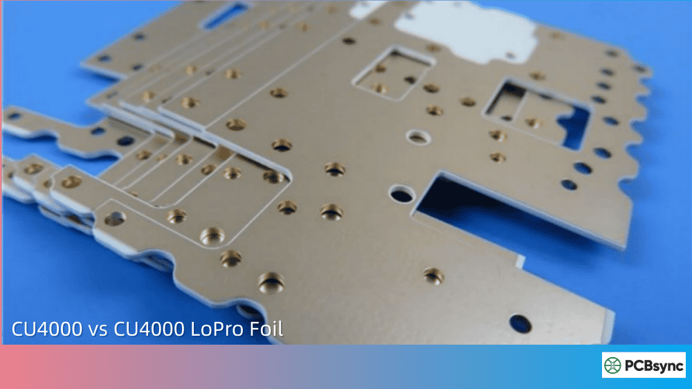
If you’ve been designing high-frequency multilayer boards (MLBs) using Rogers RO4000 series materials, you’ve probably faced the copper foil selection question. The choice between CU4000 and CU4000 LoPro Foil might seem straightforward at first glance, but after spending years working with these materials on 5G antenna arrays and automotive radar projects, I can tell you there’s more nuance here than most datasheets reveal.
This guide breaks down everything you need to know about CU4000 vs CU4000 LoPro Foil selection, backed by real-world performance data and practical design considerations that will help you make informed decisions for your next high-frequency MLB project.
Rogers Corporation developed CU4000 and CU4000 LoPro electrodeposited copper foils specifically for multilayer board constructions using RO4000 cores and prepreg materials. Both foils carry an IPC-4562 Grade 3 designation, meaning they meet high-temperature elongation requirements essential for reliable MLB fabrication.
CU4000 ED Foil is a high-performance, single-side treated electrodeposited copper foil. Rogers engineered it with an increased mechanical bonding area to provide exceptional peel strength when bonded to RO4400 series prepregs. The treatment creates a textured matte surface that physically interlocks with the prepreg resin during lamination.
CU4000 LoPro Foil takes a different approach. It’s a reverse-treated electrodeposited copper foil that bonds the smooth drum side to the dielectric using a thin adhesive layer (approximately 0.00035″ thick). This construction delivers significantly lower conductor loss compared to standard ED foil while maintaining reliable adhesion to RO4000 materials.
The key distinction here involves how each foil type balances the competing requirements of mechanical adhesion and electrical performance. Standard CU4000 prioritizes bond strength through surface roughness, while CU4000 LoPro optimizes for reduced insertion loss through smoother copper-dielectric interfaces.
Why Copper Surface Roughness Matters for High-Frequency MLB Design
Before diving deeper into the CU4000 vs CU4000 LoPro Foil comparison, understanding why surface roughness impacts high-frequency performance is critical for making the right choice.
At microwave and millimeter-wave frequencies, electromagnetic energy concentrates near the conductor surface due to skin effect. The skin depth equation shows this concentration increases with frequency:
When frequencies reach 10 GHz and above, skin depth shrinks to sub-micron levels. At 24 GHz, typical skin depth in copper is approximately 0.42 μm. This means high-frequency currents flow through an extremely thin layer at the conductor surface.
Here’s where surface roughness becomes problematic. When surface roughness approaches or exceeds the skin depth, current paths become longer as they follow the contours of peaks and valleys on the copper surface. This increased path length translates directly to higher conductor loss.
Standard ED copper typically exhibits surface roughness (Rz) values of 7-10 μm on the matte side. At 24 GHz, research data shows microstrip lines fabricated with ED copper can exhibit up to 40% higher insertion loss compared to low-profile alternatives.
Technical Specifications: CU4000 vs CU4000 LoPro Foil
The following table summarizes the key specifications from the Rogers datasheet for both foil types:
Property
CU4000 ED (½ oz)
CU4000 ED (1 oz)
CU4000 LoPro (½ oz)
CU4000 LoPro (1 oz)
Test Method
Nominal Thickness
18 µm
35 µm
18 µm
35 µm
–
Area Weight
½ oz/ft²
1 oz/ft²
½ oz/ft²
1 oz/ft²
–
Tensile Strength (RT)
48 kpsi
48 kpsi
62 kpsi
58 kpsi
IPC-TM-650, 2.4.18B
Tensile Strength (180°C)
26 kpsi
26 kpsi
33 kpsi
34 kpsi
IPC-TM-650, 2.4.18B
Elongation (RT)
10%
14%
10%
16%
IPC-TM-650, 2.4.18B
Elongation (180°C)
7%
7%
8%
8%
IPC-TM-650, 2.4.18B
Surface Roughness (Rz) Matte Side
7-10 µm
8-13 µm
2-3 µm
2-3 µm
IPC-TM-650, 2.2.17
Several observations stand out from this data. The CU4000 LoPro shows notably higher tensile strength at both room temperature and elevated temperature compared to standard CU4000 ED. This improved mechanical performance comes from the reverse-treatment process and adhesive layer construction.
The surface roughness difference is dramatic. CU4000 LoPro achieves Rz values of 2-3 µm compared to 7-13 µm for standard CU4000 ED. This 3-4x reduction in surface roughness directly impacts conductor loss at high frequencies.
Both foils are compatible with RO4450B, RO4450F, RO4450T, and RO4460G2 prepregs for foil lamination MLB constructions.
Real-world insertion loss measurements demonstrate the practical impact of choosing CU4000 vs CU4000 LoPro Foil. Published test data using RO4350B substrates at 24 GHz shows approximately 40% lower insertion loss for LoPro copper compared to standard ED copper.
Frequency
ED Copper (Approx.)
LoPro Copper (Approx.)
Improvement
10 GHz
Baseline
15-20% lower
Moderate
24 GHz
Baseline
~40% lower
Significant
77 GHz
Baseline
~45% lower
Substantial
This improvement stems entirely from reduced conductor loss. At frequencies below 10 GHz, dielectric loss dominates total insertion loss. As frequency increases, conductor loss becomes increasingly significant, making copper surface roughness a critical factor.
For automotive radar applications operating at 77 GHz, the insertion loss difference becomes even more pronounced. Rogers materials like RO4830 with LoPro copper achieve insertion loss values around 2.2 dB/inch at 77 GHz, which is essential for reliable sensor performance.
When to Choose CU4000 Standard ED Foil
Standard CU4000 ED foil remains the right choice for certain applications:
Lower frequency applications (below 6-10 GHz): When dielectric loss dominates total insertion loss, the reduced conductor loss from LoPro copper provides diminishing returns. The cost premium of LoPro foil may not be justified.
Applications requiring maximum peel strength: Some mechanical stress conditions or thermal cycling requirements may favor the higher intrinsic bond strength of rougher copper surfaces. While CU4000 LoPro maintains adequate peel strength for most applications, standard CU4000 ED provides additional margin.
Cost-sensitive high-volume production: Standard ED foil costs less than LoPro alternatives. For applications where insertion loss specifications can be met with standard copper, the economics favor CU4000 ED.
Hybrid MLB constructions: When Rogers PCB high-frequency layers are combined with FR-4 for power and ground planes, the outer layers using CU4000 ED may provide adequate performance while reducing material costs.
When CU4000 LoPro Foil Is Essential
CU4000 LoPro Foil becomes necessary or strongly preferred in these scenarios:
5G infrastructure and base station antennas: Modern cellular infrastructure operates at frequencies where conductor loss significantly impacts system performance. Additionally, passive intermodulation (PIM) requirements for base station antennas favor low-profile copper foils. LoPro copper consistently achieves better PIM performance compared to standard ED copper.
Automotive radar (24 GHz and 77 GHz): ADAS radar sensors demand minimal insertion loss for accurate target detection. The difference between ED and LoPro copper directly impacts radar range and resolution. Most automotive OEMs now specify LoPro copper for radar PCB applications.
Millimeter-wave communications: As 5G mmWave deployments expand into 28 GHz and 39 GHz bands, conductor loss becomes a primary performance limiter. CU4000 LoPro enables practical circuit designs at these frequencies.
High-frequency test equipment: Automated test equipment (ATE) and measurement systems benefit from reduced insertion loss to maintain signal integrity across wide frequency ranges.
Satellite communications: Space applications combine demanding electrical performance requirements with reliability concerns. LoPro copper helps meet insertion loss budgets while maintaining the mechanical integrity needed for launch and orbital environments.
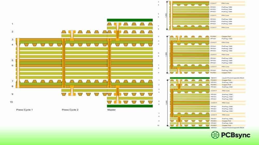
MLB Construction Best Practices with CU4000 Foils
Designing multilayer boards with CU4000 or CU4000 LoPro requires attention to several construction details:
Prepreg Selection and Compatibility
Both CU4000 foil types are qualified for use with RO4400 series prepregs. The table below shows compatible prepreg options:
Prepreg
Dk (Design)
Thickness Options
Key Characteristics
RO4450B
3.54
3.5, 4, 5 mil
Standard flow properties
RO4450F
3.52
4 mil
Improved lateral flow control
RO4450T
3.23-3.35
3, 4, 5 mil
Thin options for MLB flexibility
RO4460G2
6.15
2.5, 5, 10 mil
High-Dk applications
RO4450T deserves particular mention for complex MLB constructions. Its thinner options (down to 3 mil) enable tighter layer-to-layer spacing essential for controlled impedance at higher frequencies.
Foil Lamination Process Considerations
CU4000 and CU4000 LoPro foils simplify MLB registration compared to standard copper-clad laminates. By eliminating the need to etch inner-layer patterns before lamination, foil lamination reduces registration error sources and improves yield.
Key process parameters for foil lamination with RO4000 materials:
Lamination temperature: Typically 375-400°F (190-205°C) per Rogers recommendations
Pressure: 200-350 psi depending on stack configuration
Cycle time: Usually 60-90 minutes for full cure
The thin adhesive layer on CU4000 LoPro adds approximately 0.00035″ to total thickness. Account for this in stackup calculations, particularly for tight impedance tolerance designs.
HDI and Build-Up Compatibility
Both foil types support HDI (High Density Interconnect) and sequential build-up technology. The IPC-4562 Grade 3 high-temperature elongation designation ensures reliability through multiple lamination cycles required for complex sequential lamination processes.
For laser drilling applications, RO4835T cores combined with RO4450T bondply and CU4000 LoPro outer foils create an optimized stackup for mmWave applications requiring microvias and fine features.
Passive Intermodulation (PIM) Considerations
For base station antenna designers, PIM performance often drives copper foil selection. Passive intermodulation occurs when nonlinearities in the antenna system generate spurious signals that interfere with receive channels.
Copper surface roughness contributes to PIM through microscale metal-oxide-metal junctions at the copper surface. Low-profile copper foils like CU4000 LoPro reduce these nonlinear junctions, improving PIM performance.
Rogers has extensively characterized PIM performance of their antenna-grade materials. While specific PIM values depend on circuit design, fabrication quality, and test methods, LoPro copper consistently outperforms standard ED copper in PIM testing.
For designs targeting PIM levels below -150 dBc (a common specification for modern base station antennas), CU4000 LoPro is essentially mandatory when using RO4000 family materials for outer layers.
Design Guidelines for Minimizing Insertion Loss
Beyond copper foil selection, several design practices help minimize insertion loss in high-frequency MLB designs:
Optimize trace width: Wider traces increase the effective conductor cross-section, reducing both DC and AC resistance. Balance trace width against impedance requirements and routing density constraints.
Consider stripline vs. microstrip: Stripline structures (buried between ground planes) provide shielding benefits but may have higher insertion loss than microstrip due to increased dielectric volume. Evaluate trade-offs based on frequency and isolation requirements.
Minimize layer transitions: Each via transition adds insertion loss and potentially creates impedance discontinuities. Route critical high-frequency signals on single layers where possible.
Control dielectric thickness variation: Impedance variations from Dk and thickness changes cause reflections that contribute to apparent insertion loss. Specify materials with tight Dk tolerance and work with fabricators who can maintain thickness control.
Surface finish selection: The conductor surface exposed to air (top of microstrip traces) also affects conductor loss. Consider immersion silver (IAg) or ENEPIG finishes, which can provide smoother final surfaces than HASL.
Stackup Examples for Common Applications
4-Layer 77 GHz Automotive Radar
Layer
Material
Thickness
Copper
Notes
L1
CU4000 LoPro
18 µm (½ oz)
Antenna/RF
Smooth surface for mmWave
Prepreg
RO4450T
3 mil
–
Low-Dk bondply
L2
RO4835T Core
5 mil
Ground
Spread glass, Dk 3.3
L3
–
–
Ground
On opposite side of core
Prepreg
RO4450T
3 mil
–
Low-Dk bondply
L4
CU4000 LoPro
18 µm (½ oz)
RF feed
Smooth surface
6-Layer 5G Base Station Antenna
Layer
Material
Thickness
Copper
Notes
L1
CU4000 LoPro
35 µm (1 oz)
Patch elements
PIM optimized
Prepreg
RO4450F
4 mil
–
Controlled flow
L2/L3
RO4350B LoPro Core
10 mil
Signal/Ground
Low-loss core
Prepreg
RO4450B
5 mil
–
Standard bondply
L4/L5
FR-4 Core
10 mil
Power/Ground
Cost reduction
Prepreg
RO4450F
4 mil
–
Controlled flow
L6
CU4000 LoPro
35 µm (1 oz)
Feed network
PIM optimized
Thermal and Reliability Considerations
Beyond electrical performance, thermal behavior and long-term reliability play critical roles in high-frequency MLB design. Both CU4000 and CU4000 LoPro foils carry IPC-4562 Grade 3 certification for high-temperature elongation, ensuring they can withstand the thermal stresses of lead-free assembly and demanding operating environments.
Thermal Cycling Performance
The coefficient of thermal expansion (CTE) mismatch between copper and dielectric materials creates mechanical stress during temperature cycling. Both CU4000 foil variants exhibit good high-temperature elongation (7-8% at 180°C), which helps absorb thermal stresses without cracking.
For automotive applications, where junction temperatures can reach 125°C or higher during operation, this thermal resilience is essential. The RO4000 series laminates themselves feature low z-axis CTE (matching copper more closely than FR-4), which complements the CU4000 foils’ mechanical properties.
Lead-Free Assembly Compatibility
Modern electronics manufacturing requires lead-free soldering with peak reflow temperatures reaching 260°C. Both CU4000 and CU4000 LoPro foils maintain integrity through these demanding thermal profiles when used with RO4000 materials. The high glass transition temperature (Tg > 280°C) of RO4000 laminates ensures the dielectric remains stable throughout assembly.
The thin adhesive layer on CU4000 LoPro does not compromise lead-free compatibility. Rogers has qualified the complete CU4000 LoPro system for standard lead-free processes, including multiple reflow cycles required for complex assemblies.
Oxidation Resistance
Prolonged exposure to elevated temperatures in oxidative environments can affect hydrocarbon-based laminates. For applications requiring extended high-temperature operation, consider RO4835 series materials, which offer 10x improved oxidation resistance compared to standard RO4350B.
When combined with CU4000 LoPro foil, RO4835 and RO4835T materials provide an optimized solution for demanding aerospace, defense, and industrial applications where both electrical performance and long-term reliability are non-negotiable.
Manufacturing Considerations and Fabricator Selection
Successfully implementing CU4000 or CU4000 LoPro in production requires working with fabricators experienced in high-frequency materials. Not all PCB manufacturers have the equipment and expertise needed for RF/microwave multilayer constructions.
Key Fabricator Capabilities
When selecting a fabricator for MLB designs using CU4000 foils, verify the following capabilities:
Material handling experience: Rogers materials require different handling than standard FR-4. Fabricators should have documented processes for receiving, storing, and processing RO4000 series laminates and CU4000 foils.
Controlled lamination: Foil lamination MLB processes demand precise temperature, pressure, and time control. Ask potential fabricators about their lamination equipment and process capabilities.
Registration capability: High-frequency MLBs often require tighter layer-to-layer registration than standard PCBs. Verify the fabricator can achieve required registration tolerances for your design.
Impedance control: RF and microwave circuits demand precise impedance control. Request the fabricator’s typical impedance tolerance capabilities and ask for test data demonstrating consistency.
Surface finish options: Different surface finishes affect both solderability and RF performance. Ensure the fabricator offers appropriate finishes (immersion silver, ENEPIG, etc.) for your application.
Cost Optimization Strategies
High-frequency materials like CU4000 LoPro carry cost premiums compared to standard materials. Several strategies can help optimize project costs without sacrificing performance:
Use LoPro only where needed: For multilayer designs, consider using CU4000 LoPro on outer layers and RF-critical inner layers, while using standard copper or CU4000 ED on layers where loss is less critical.
Right-size panel utilization: Work with your fabricator to optimize panel layouts. High-frequency materials are expensive, so maximizing board yield per panel reduces per-unit costs.
Standardize stackups: Developing standardized stackups that can serve multiple products reduces NRE costs and improves fabricator familiarity with your designs.
Plan for volume: Material costs decrease with volume. If your application will scale to production quantities, factor volume pricing into your material decisions.
Useful Resources for Rogers Material Design
The following resources provide essential reference information for engineers working with CU4000 and CU4000 LoPro foils:
Official Rogers Resources
Rogers Technology Support Hub: Access calculators, conversion tools, and technical papers at rogerscorp.com
CU4000 and CU4000 LoPro Datasheet: Publication #92-176, available for download from Rogers website
RO4000 Series Datasheet: Comprehensive specifications for all RO4000 laminates and prepregs
Copper Foils for High Frequency Materials: Technical white paper covering surface roughness effects and foil selection
Design Tools
Rogers Microwave Impedance Calculator (MWI): Free tool for transmission line design with Rogers materials
Bonding Material Selector Tool: Helps identify compatible prepregs for specific laminate combinations
IPC Standards Reference
IPC-4562: Specification for metal foil for printed wiring applications
IPC-4101: Specification for base materials for rigid and multilayer printed boards
IPC-6012: Qualification and performance specification for rigid printed boards
Fabrication Partners
Contact Rogers Corporation directly for their qualified fabricator network. These fabricators have demonstrated capability with RO4000 series materials and can provide guidance on design for manufacturability.
CU4000 vs CU4000 LoPro Foil: Quick Selection Guide
Application
Frequency Range
Recommended Foil
Primary Reason
Power amplifiers
<6 GHz
CU4000 ED
Cost effectiveness
WiFi 6E modules
6 GHz
Either
Evaluate based on loss budget
5G sub-6 GHz
3.5-6 GHz
CU4000 LoPro
Future-proofing, PIM
5G mmWave
24-39 GHz
CU4000 LoPro
Essential for loss
Automotive radar
24/77 GHz
CU4000 LoPro
Essential for performance
Base station antennas
0.7-6 GHz
CU4000 LoPro
PIM requirements
Satellite ground terminals
Ku/Ka band
CU4000 LoPro
Loss and reliability
General RF/microwave
Variable
Evaluate
Based on specifications
Conclusion: Making the Right CU4000 vs CU4000 LoPro Foil Decision
The choice between CU4000 and CU4000 LoPro Foil ultimately comes down to your specific frequency range, performance requirements, and budget constraints. For applications operating above 10 GHz, particularly in 5G mmWave, automotive radar, and satellite communications, CU4000 LoPro provides measurable benefits that often justify its cost premium. The 40% reduction in insertion loss at 24 GHz and improved PIM performance can mean the difference between meeting and missing your design specifications.
For lower-frequency applications or cost-sensitive designs where insertion loss margins are comfortable, standard CU4000 ED foil remains an excellent choice. Its higher intrinsic bond strength and lower cost make it appropriate for power amplifier modules, sub-6 GHz wireless, and many general RF applications.
The key is making an informed decision based on quantitative analysis rather than assumptions. Use Rogers’ design tools to model your specific circuits, consult with experienced fabricators, and prototype critical designs with both foil types if the decision isn’t clear-cut. The upfront engineering investment in proper material selection pays dividends in successful first-pass designs and reliable production performance.
Frequently Asked Questions
What is the main difference between CU4000 and CU4000 LoPro Foil?
The primary difference between CU4000 and CU4000 LoPro Foil lies in their surface treatment and resulting surface roughness. Standard CU4000 is a single-side treated ED foil with surface roughness (Rz) of 7-13 µm, optimized for mechanical bond strength. CU4000 LoPro uses reverse-treated copper with a thin adhesive layer, achieving surface roughness of just 2-3 µm. This smoother surface significantly reduces conductor loss at high frequencies while maintaining adequate adhesion to RO4400 series prepregs.
How much does CU4000 LoPro improve insertion loss compared to standard CU4000?
At 24 GHz, test data shows CU4000 LoPro can reduce insertion loss by approximately 40% compared to standard CU4000 ED foil on equivalent RO4350B substrates. The improvement increases with frequency due to skin effect—at 77 GHz, the insertion loss advantage of LoPro copper becomes even more pronounced. Below 6-10 GHz, the improvement is more modest as dielectric loss dominates total insertion loss at lower frequencies.
Can I use CU4000 foils with FR-4 prepregs in hybrid MLB constructions?
CU4000 and CU4000 LoPro foils are specifically designed and qualified for use with Rogers RO4400 series prepregs (RO4450B, RO4450F, RO4450T, RO4460G2). For hybrid constructions combining Rogers and FR-4 materials, you would typically use the CU4000 foils on the Rogers prepreg layers and standard copper-clad FR-4 for the FR-4 portions of the stackup. Consult with your fabricator and Rogers technical support for specific hybrid construction guidance.
Does CU4000 LoPro cost more than standard CU4000?
Yes, CU4000 LoPro foil carries a cost premium over standard CU4000 ED foil due to the additional processing required for reverse treatment and adhesive application. The exact price difference varies by supplier and volume, but engineers should factor this into project budgets. For applications where the performance improvement justifies the cost—particularly above 10 GHz or where PIM is critical—the investment typically provides good value through improved system performance or reduced PCB redesign iterations.
What prepreg thickness should I use with CU4000 LoPro for 77 GHz designs?
For 77 GHz automotive radar and similar mmWave applications, thinner prepreg options generally provide better performance. RO4450T in 3 mil thickness is commonly used for these designs, offering low Dk (3.23-3.35) and good flow characteristics. The thin adhesive layer on CU4000 LoPro adds approximately 0.35 mil to the stackup, which must be accounted for in impedance calculations. Work with Rogers’ MWI calculator and your fabricator to optimize the specific stackup for your impedance and layer spacing requirements.
Inquire: Call 0086-755-23203480, or reach out via the form below/your sales contact to discuss our design, manufacturing, and assembly capabilities.
Quote: Email your PCB files to Sales@pcbsync.com (Preferred for large files) or submit online. We will contact you promptly. Please ensure your email is correct.
Notes: For PCB fabrication, we require PCB design file in Gerber RS-274X format (most preferred), *.PCB/DDB (Protel, inform your program version) format or *.BRD (Eagle) format. For PCB assembly, we require PCB design file in above mentioned format, drilling file and BOM. Click to download BOM template To avoid file missing, please include all files into one folder and compress it into .zip or .rar format.


