Inquire: Call 0086-755-23203480, or reach out via the form below/your sales contact to discuss our design, manufacturing, and assembly capabilities.
Quote: Email your PCB files to Sales@pcbsync.com (Preferred for large files) or submit online. We will contact you promptly. Please ensure your email is correct.
Notes: For PCB fabrication, we require PCB design file in Gerber RS-274X format (most preferred), *.PCB/DDB (Protel, inform your program version) format or *.BRD (Eagle) format. For PCB assembly, we require PCB design file in above mentioned format, drilling file and BOM. Click to download BOM template To avoid file missing, please include all files into one folder and compress it into .zip or .rar format.
If you’ve been searching for a cost-effective high-frequency laminate that doesn’t compromise on phase stability, CLTE-AT deserves your attention. After working with dozens of RF materials over the years, I can tell you this ceramic-filled PTFE composite hits a sweet spot that many engineers overlook.
In this guide, I’ll walk you through everything you need to know about CLTE-AT—from raw specifications to real-world design considerations. Whether you’re designing automotive radar antennas or temperature-stable filters, understanding this material can save you significant headaches down the road.
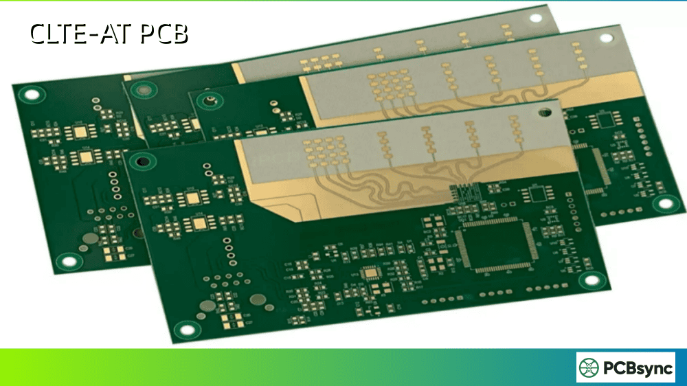
CLTE-AT is a commercial-grade laminate developed by Rogers Corporation as part of their CLTE Series product line. The material consists of micro-dispersed ceramic particles embedded in a PTFE (polytetrafluoroethylene) matrix, reinforced with woven glass fabric for dimensional stability.
What sets CLTE-AT apart from other high-frequency laminates is its origin story. Rogers developed it specifically to optimize the cost-to-performance ratio, making premium RF performance accessible for commercial applications without the price tag typically associated with military-grade materials.
The “AT” designation indicates this is the “Affordable Technology” variant of the CLTE family. It shares the fundamental building blocks of the premium CLTE-XT material but incorporates manufacturing adjustments that reduce costs while maintaining impressive electrical performance.
Why CLTE-AT Matters for RF Design
For RF engineers, material selection directly impacts circuit performance. CLTE-AT addresses several pain points common in high-frequency design:
Consistent dielectric constant across different thicknesses
Excellent phase stability over wide temperature ranges
Lower insertion loss compared to conventional FR-4
Better plated through-hole reliability than standard PTFE laminates
CLTE-AT Technical Specifications
Let’s dive into the numbers. The following specifications are based on Rogers Corporation’s official datasheet (IPC Slash Sheet #4103B/006).
Electrical Properties of CLTE-AT
Property
Value
Test Conditions
Standard
Dielectric Constant (Dk)
3.00
23°C, 50% RH, 10 GHz
IPC TM-650 2.5.5.5
Dissipation Factor (Df)
0.0013
23°C, 50% RH, 10 GHz
IPC TM-650 2.5.5.5
Thermal Coefficient of Dk (TCDk)
-10 ppm/°C
0 to 100°C, 10 GHz
IPC TM-650 2.5.5.5
Volume Resistivity
4.25 × 10⁸ MΩ-cm
C-96/35/90
IPC TM-650 2.5.17.1
The Dk of 3.00 might seem slightly higher than CLTE-XT’s 2.94, but this trade-off enables the cost savings that make CLTE-AT commercially viable. For most applications, this difference is negligible.
Thermal Properties of CLTE-AT
Thermal performance separates good RF materials from great ones. Here’s what CLTE-AT delivers:
Property
X-Axis
Y-Axis
Z-Axis
Test Method
CTE (Coefficient of Thermal Expansion)
9 ppm/°C
12 ppm/°C
34 ppm/°C
IPC TM-650 2.4.41
Thermal Conductivity
0.62 W/m/K
–
–
ASTM E1461
Operating Temperature
-55°C to +150°C
–
–
–
The low CTE values in X and Y directions are particularly valuable for multilayer constructions where dimensional stability during thermal cycling prevents registration issues and maintains impedance control.
The Z-axis CTE of 34 ppm/°C deserves attention. While higher than X and Y values (which is typical for all laminates), this value is significantly lower than standard FR-4 (around 60-70 ppm/°C below Tg). This matters enormously for plated through-hole reliability—lower Z-axis expansion means less stress on copper plating during thermal cycling, translating to longer service life in demanding applications.
The thermal conductivity of 0.62 W/m/K exceeds standard FR-4 (approximately 0.3 W/m/K) by roughly double. For high-power amplifier applications or densely packed circuits, this improved heat spreading can reduce hot spots and extend component life.
Mechanical Properties of CLTE-AT
Property
Value
Test Conditions
Peel Strength (1 oz ED copper)
8.0 lb/in (1.4 N/mm)
After solder float
Flexural Strength
18,000 psi (124 MPa)
–
Water Absorption
0.02%
D-24/23
Density
2.20 g/cm³
–
The exceptionally low water absorption (0.02%) means CLTE-AT maintains stable electrical properties even in humid environments—a critical factor for outdoor antenna installations.
CLTE-AT vs CLTE-XT vs CLTE: Which One Should You Choose?
Understanding the differences between CLTE variants helps you make informed material selections. Here’s a direct comparison:
Parameter
CLTE-AT
CLTE-XT
CLTE
Dielectric Constant (Dk)
3.00
2.94
2.94
Dissipation Factor (Df)
0.0013
0.0010
0.0012
TCDk (ppm/°C)
-10
-6
-10
Target Market
Commercial
Mil/Aero
General Purpose
Relative Cost
$$
$$$$
$$$
Panel Size Options
Limited
Full Range
Full Range
Copper Foil Options
Standard ED
Multiple Types
Multiple Types
When to Choose CLTE-AT
CLTE-AT is your best choice when:
Budget constraints matter but you can’t sacrifice RF performance
Applications require temperature stability without military-grade pricing
Commercial automotive or industrial radar systems
High-volume production where material cost impacts profitability
When to Choose CLTE-XT Instead
Consider CLTE-XT for:
Military and aerospace applications with strict insertion loss requirements
Systems where every 0.0003 of Df matters
Projects requiring specific panel sizes or copper foil options unavailable in CLTE-AT
Applications of CLTE-AT PCB Material
CLTE-AT finds its home in applications where phase stability and consistent RF performance intersect with commercial viability.
Automotive Radar Systems
The automotive industry has embraced CLTE-AT for ADAS (Advanced Driver Assistance Systems) components. Applications include:
Collision avoidance radar at 24 GHz and 77 GHz
Adaptive cruise control antenna substrates
Blind spot detection systems
Parking assist sensors
The material’s phase stability ensures accurate distance measurements across the temperature extremes found in automotive environments (-40°C to +85°C ambient). This is critical because phase errors in radar systems translate directly to distance measurement errors—a potentially dangerous issue for safety-critical ADAS functions.
What makes CLTE-AT particularly attractive for automotive is the cost factor. Modern vehicles may contain 5-10 radar sensors each. At automotive production volumes of millions of units, even small per-unit cost savings multiply into substantial numbers. CLTE-AT lets Tier 1 suppliers meet OEM performance specifications while maintaining competitive pricing.
The consistent Dk across thickness variations makes CLTE-AT valuable for antenna arrays where multiple elements must maintain precise phase relationships. In phased arrays, element-to-element phase consistency directly affects beam steering accuracy and sidelobe performance. Material inconsistencies cause performance degradation—something CLTE-AT minimizes through its controlled manufacturing process.
For base station antennas operating outdoors, the low moisture absorption (0.02%) ensures electrical properties remain stable through seasonal humidity variations. This stability reduces the need for field calibration and extends maintenance intervals.
Industrial and IoT Applications
The cost-performance balance makes CLTE-AT attractive for:
Industrial automation sensors
Smart city infrastructure
Agricultural monitoring systems
Building automation radar sensors
Understanding the CLTE-AT Material Structure
Before diving into design guidelines, it helps to understand what’s actually inside this laminate. CLTE-AT uses a sophisticated composite architecture that delivers its unique properties.
The Ceramic-PTFE Matrix
The core of CLTE-AT consists of micro-dispersed ceramic particles uniformly distributed throughout a PTFE (Teflon) base. This isn’t just ceramic powder mixed into plastic—the ceramic particles are engineered to specific size distributions and dispersed at the molecular level to ensure consistent properties across the entire panel.
The ceramic loading serves multiple purposes:
Dielectric control: Adjusts the Dk to the target 3.00 value
Thermal management: Improves thermal conductivity over pure PTFE
CTE reduction: Lowers expansion coefficients for better dimensional stability
Mechanical strength: Enhances rigidity compared to unfilled PTFE
Consistent mechanical properties across temperature ranges
Better handling characteristics during fabrication
Improved registration accuracy in multilayer builds
The glass weave pattern does introduce some anisotropy in the dielectric properties—the Dk can vary slightly depending on whether your trace runs parallel or perpendicular to the weave. For most applications, this effect is negligible, but high-precision phase-sensitive designs should account for it.
Copper Cladding Options
CLTE-AT is available with electrodeposited (ED) copper foil in standard weights. While this limits flexibility compared to CLTE-XT (which offers rolled copper and various surface treatments), ED copper works well for most commercial applications. The standard 1 oz (35 µm) and 0.5 oz (18 µm) options cover the majority of design requirements.
Design Guidelines for CLTE-AT PCB
Designing with CLTE-AT requires understanding both its capabilities and limitations. Here’s practical guidance from hands-on experience.
Stack-Up Considerations
When building multilayer structures with CLTE-AT:
Bonding compatibility: Use Rogers-recommended bondply materials (like 2929 or CuClad bondply) for best results
Hybrid designs: CLTE-AT can be combined with FR-4 for non-critical layers to reduce costs, but keep RF signal layers on CLTE-AT cores
Thickness selection: Standard thicknesses range from 0.010″ to 0.060″—verify availability before finalizing your design
Impedance Control Tips
Use the manufacturer’s Dk value of 3.00 for initial calculations
Account for the -10 ppm/°C TCDk when designing for wide temperature ranges
The woven glass reinforcement can cause some Dk variation depending on trace orientation relative to the weave—consider this for critical transmission lines
Fabrication Recommendations
CLTE-AT processes similarly to other PTFE-based materials:
Process Step
Recommendation
Drilling
Use highly polished carbide tools; avoid repointed bits
Surface Prep
Chemical cleaning preferred; avoid mechanical scrubbing
Etching
Standard ammoniacal or cupric etchants work fine
Lamination
Follow Rogers guidelines for pressure and temperature profiles
Pre-bake
1-2 hours at 110°C-120°C before solder operations
Common Design Mistakes to Avoid
From experience, watch out for these pitfalls:
Ignoring panel size limitations: CLTE-AT has fewer panel options than CLTE-XT—confirm availability early
Assuming FR-4 processing: While similar, PTFE materials have unique handling requirements
Overlooking moisture sensitivity: Pre-bake panels that have been stored for extended periods
Neglecting bondply selection: Mismatched bondply can compromise multilayer reliability
How to Source CLTE-AT Material
Procurement is straightforward if you know where to look.
Direct from Rogers Corporation
Rogers maintains regional offices and distribution networks globally. Contact them directly for:
Technical support and material recommendations
Sample requests for prototyping
High-volume pricing discussions
Authorized Distributors
Several distributors stock CLTE-AT or can source it:
Richardson RFPD
Digi-Key (limited stock)
Mouser Electronics (limited selection)
Regional specialty distributors
Lead Time Considerations
Plan accordingly:
Stock items: 1-2 weeks typical
Custom orders: 4-8 weeks depending on specifications
Prototype quantities: Often available from fabricators with material inventory
Useful Resources and Downloads
Having the right documentation makes design work smoother. Here are essential resources:
Ansys HFSS: Full-wave simulation with Rogers material library
Technical Papers
Rogers publishes application notes covering:
Fabrication guidelines for PTFE materials
Thermal management in high-frequency circuits
Antenna design considerations
Frequently Asked Questions About CLTE-AT
What is the dielectric constant of CLTE-AT?
CLTE-AT has a dielectric constant (Dk) of 3.00 when measured at 10 GHz, 23°C, and 50% relative humidity according to IPC TM-650 2.5.5.5. This value remains remarkably stable across different material thicknesses, which is one of the material’s key advantages for consistent RF design.
Is CLTE-AT suitable for multilayer PCB construction?
Yes, CLTE-AT works well in multilayer configurations. Its low CTE values (9/12/34 ppm/°C in X/Y/Z) provide excellent plated through-hole reliability. For best results, use Rogers-compatible bondply materials and follow recommended lamination parameters. The material supports complex structures common in phased array and antenna feed networks.
How does CLTE-AT compare to RO4350B for high-frequency applications?
Both materials serve high-frequency applications but differ in key ways. CLTE-AT offers better phase stability over temperature due to its lower TCDk (-10 ppm/°C vs -50 ppm/°C for RO4350B). However, RO4350B uses standard FR-4 processing and offers easier fabrication. Choose CLTE-AT when temperature stability is critical; choose RO4350B when manufacturing simplicity matters more.
What frequency range is CLTE-AT designed for?
CLTE-AT performs well from RF through millimeter-wave frequencies. The material’s specifications are characterized at 10 GHz, and it’s commonly used in applications from 1 GHz to 77 GHz. For frequencies above 40 GHz, verify insertion loss requirements against the Df of 0.0013 to ensure it meets your system loss budget.
Can CLTE-AT be used with lead-free soldering processes?
Yes, CLTE-AT is compatible with lead-free soldering. The material’s thermal stability up to 150°C operating temperature and its low moisture absorption (0.02%) make it suitable for higher-temperature reflow profiles. Pre-bake the material at 110°C-120°C for 1-2 hours before soldering to ensure optimal results.
Making the Right Material Choice
CLTE-AT represents Rogers Corporation’s answer to a common industry challenge: how do you deliver military-grade RF performance at commercial prices? By thoughtfully optimizing the CLTE platform for cost efficiency while preserving critical electrical properties, they’ve created a material that serves the growing commercial radar and antenna market effectively.
For your next high-frequency project, consider CLTE-AT when phase stability matters but budget constraints are real. It won’t be the right choice for every application—sometimes you genuinely need the premium performance of CLTE-XT or the processing simplicity of RO4350B. But when the requirements align, CLTE-AT delivers exceptional value.
The key is matching material capabilities to application requirements. Understand your frequency, temperature range, loss budget, and cost targets, then select accordingly. With the specifications and guidance in this article, you’re equipped to make that decision confidently.
Summary: Key Takeaways for CLTE-AT Selection
To wrap up, here are the essential points to remember when considering CLTE-AT for your next design:
Consideration
CLTE-AT Strength
Phase Stability
Excellent TCDk of -10 ppm/°C
Cost
More affordable than CLTE-XT
Frequency Range
Effective from RF through 77 GHz
Temperature Range
-55°C to +150°C operating
Moisture Resistance
Outstanding 0.02% absorption
PTH Reliability
Low Z-CTE improves via life
Remember that no material is perfect for every situation. CLTE-AT excels in commercial applications demanding temperature-stable RF performance at reasonable cost. For extreme precision requirements, look at CLTE-XT. For easier processing at lower frequencies, consider RO4350B or similar hydrocarbon-based options.
The best material choice comes from honestly assessing your requirements against available options. CLTE-AT has earned its place in the RF designer’s toolkit—use it where it fits, and your designs will benefit.
Inquire: Call 0086-755-23203480, or reach out via the form below/your sales contact to discuss our design, manufacturing, and assembly capabilities.
Quote: Email your PCB files to Sales@pcbsync.com (Preferred for large files) or submit online. We will contact you promptly. Please ensure your email is correct.
Notes: For PCB fabrication, we require PCB design file in Gerber RS-274X format (most preferred), *.PCB/DDB (Protel, inform your program version) format or *.BRD (Eagle) format. For PCB assembly, we require PCB design file in above mentioned format, drilling file and BOM. Click to download BOM template To avoid file missing, please include all files into one folder and compress it into .zip or .rar format.


