Inquire: Call 0086-755-23203480, or reach out via the form below/your sales contact to discuss our design, manufacturing, and assembly capabilities.
Quote: Email your PCB files to Sales@pcbsync.com (Preferred for large files) or submit online. We will contact you promptly. Please ensure your email is correct.
Notes: For PCB fabrication, we require PCB design file in Gerber RS-274X format (most preferred), *.PCB/DDB (Protel, inform your program version) format or *.BRD (Eagle) format. For PCB assembly, we require PCB design file in above mentioned format, drilling file and BOM. Click to download BOM template To avoid file missing, please include all files into one folder and compress it into .zip or .rar format.
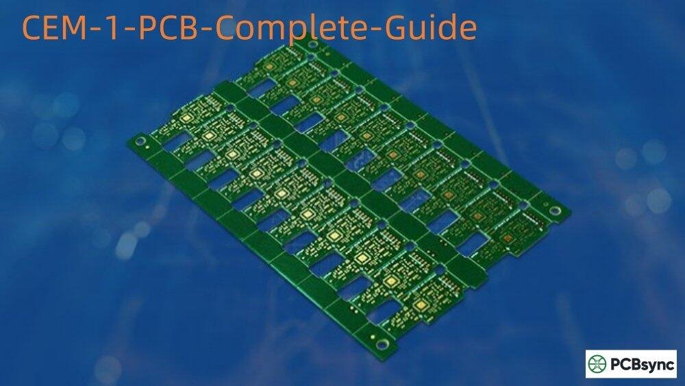
If you’ve been designing PCBs for consumer electronics or LED lighting, you’ve probably come across CEM-1 as a material option. After 15 years of working with various substrate materials, I can tell you that CEM-1 PCB remains one of the most underrated materials in our industry. It’s not glamorous, it won’t win you any awards for cutting-edge design, but when cost optimization matters and your application fits the profile, CEM-1 delivers solid performance at a fraction of FR-4 pricing.
This guide covers everything you need to know about CEM-1 PCB material, from its composition and electrical properties to real-world applications and cost considerations. Whether you’re evaluating materials for a new product or looking to reduce BOM costs on an existing design, you’ll find practical information here based on actual manufacturing experience.
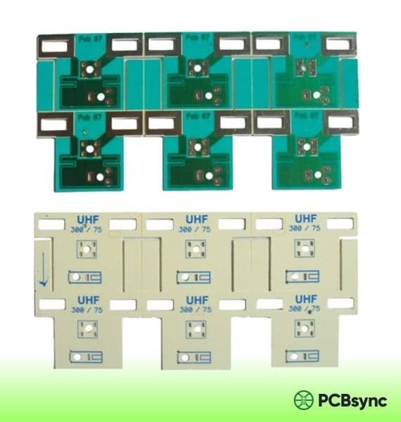
CEM-1 (Composite Epoxy Material Grade 1) is a laminate material classified under NEMA (National Electrical Manufacturers Association) standards. The material consists of three distinct layers: an inner cellulose paper core sandwiched between two layers of continuous woven glass fabric, all bonded together with flame-resistant epoxy resin.
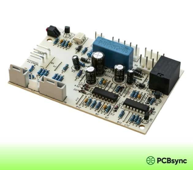
The distinctive milky-white or milky-yellow appearance of CEM-1 PCB comes from this paper-glass-epoxy composition. Unlike FR-4 which uses woven fiberglass throughout its structure, CEM-1’s paper core makes it easier to punch and process, though this same characteristic limits its use to single-layer PCB applications.
CEM-1 Composition Breakdown
Understanding the material composition helps explain both the advantages and limitations of CEM-1:
Paper Core: Cellulose-based material providing the substrate foundation
Glass Fabric Layers: Woven glass cloth on both surfaces for mechanical strength
Epoxy Resin Binder: Flame-resistant epoxy impregnating all layers
The paper core is the defining characteristic that separates CEM-1 from other PCB materials. This cellulose base cannot withstand the chemical processes required for plated through-holes (PTH), which is why CEM-1 is exclusively used for single-sided PCB designs.
CEM-1 PCB Technical Properties
When specifying CEM-1 for your project, these are the key properties you need to evaluate. The following table summarizes the typical specifications you’ll encounter from most laminate suppliers:
Property
CEM-1 Value
Test Method
Glass Transition Temp (Tg)
105-110°C
IPC-TM-650
Dielectric Constant (1MHz)
4.5-5.0
IPC-TM-650
Flammability Rating
UL 94 V-0
UL Standard
Peel Strength (1 oz Cu)
≥1.05 N/mm
IPC-TM-650 2.4.8
Thermal Stress (260°C)
≥10 seconds
IPC-TM-650 2.4.13
Punching Temperature
45-70°C
Manufacturer Spec
Bow/Twist
≤1.5%
IPC-TM-650 2.4.22
Max Operating Temp
105°C continuous
IPC-4101/10
Table 1: CEM-1 PCB Material Specifications (IPC-4101/10 compliant)
Electrical Properties of CEM-1
The electrical characteristics of CEM-1 PCB make it suitable for low-to-moderate frequency applications. The dielectric constant typically ranges from 4.5 to 5.0 at 1MHz, which is adequate for most consumer electronics operating at lower frequencies. However, for high-frequency RF applications or controlled impedance designs, FR-4 or specialized high-frequency laminates are better choices.
CEM-1’s insulation resistance and dielectric breakdown voltage meet the requirements for general-purpose electronics. The material provides reliable electrical isolation between traces when proper design rules are followed.
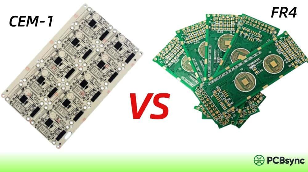
CEM-1 vs FR-4: Which Material Should You Choose?
This is probably the most common question I get from engineers evaluating substrate materials. The comparison isn’t really fair because these materials serve different purposes, but understanding the differences helps you make the right choice for your specific application.
Parameter
CEM-1
FR-4
Core Material
Paper + Glass
Woven Fiberglass
Layer Support
Single-layer only
Multi-layer (32+)
PTH Capability
Not suitable
Full support
Glass Transition (Tg)
~110°C
130-180°C
Tensile Strength
~200 MPa
~300 MPa
Moisture Absorption
Higher (paper core)
<0.15%
Machinability
Excellent (easy punch)
Good (requires routing)
Relative Cost
20-30% lower
Baseline
Table 2: CEM-1 vs FR-4 Material Comparison
The bottom line: Choose CEM-1 when your design is single-layer, cost-sensitive, and doesn’t require extreme thermal or mechanical performance. Choose FR-4 for multi-layer designs, high-reliability applications, or when you need plated through-holes.
Significant Cost Savings: Material costs run 20-30% lower than FR-4, with additional savings from easier manufacturing processes
Excellent Punchability: Can be cleanly punched at 45-70°C up to 0.093″ thickness, reducing tooling costs for high-volume production
UL 94 V-0 Flame Rating: Meets the same flammability standard as FR-4, ensuring safety compliance
Good Electrical Properties: Adequate insulation and dielectric characteristics for consumer electronics applications
Lighter Weight: Paper core makes CEM-1 boards lighter than equivalent FR-4 designs
Thermal Performance for LED: Balanced heat dissipation makes it popular in LED lighting applications
Limitations to Consider
Single-Layer Only: Paper core cannot support PTH metallization, limiting designs to one copper layer
Lower Mechanical Strength: More fragile than FR-4; requires careful handling during assembly
Moisture Sensitivity: Cellulose core absorbs moisture, which can affect long-term reliability in humid environments
Lower Temperature Rating: 105°C continuous operation limit vs 130°C+ for standard FR-4
Not for High-Frequency: Dielectric properties not suitable for RF or controlled impedance applications
CEM-1 PCB Applications: Where This Material Shines
CEM-1 has carved out a strong position in several market segments where its cost advantages outweigh its technical limitations. Here’s where you’ll commonly find CEM-1 PCB in production:
LED Lighting Industry
This is arguably the largest market for CEM-1 PCB material. LED manufacturers choose CEM-1 because it offers the best balance between heat dissipation performance and cost. For residential and commercial LED lighting where thermal demands are moderate, CEM-1 delivers adequate performance at a fraction of aluminum-core PCB pricing.
Consumer Electronics
Remote controls and wireless keyboards
Digital clocks and basic timers
Calculators and simple electronic toys
Power supply modules and adapters
Basic home appliance controllers
Industrial and Automotive
Control panels and relay boards
Automotive dashboard indicators
Turn signals and brake light circuits
Industrial sensor interfaces
Power monitoring equipment
CEM-1 PCB Cost Savings: Real Numbers
Let’s talk about actual cost savings, because that’s usually the primary driver for considering CEM-1. The savings come from multiple sources:
Raw Material Cost: CEM-1 laminates typically cost 20-30% less than equivalent FR-4 material
Tooling Savings: Punching vs routing reduces tool wear and processing time
Single-Layer Design: No PTH processing eliminates plating costs and associated steps
Volume Efficiency: Faster production cycles for high-volume manufacturing
Example calculation: For a 100mm x 50mm single-layer LED driver board produced in volumes of 10,000 units, switching from FR-4 to CEM-1 can save $0.15-0.25 per board in material alone. Add pcb manufacturing efficiency gains, and total savings can reach $2,000-3,000 per production run.
However, cost analysis must consider the complete picture. If your application requires features that CEM-1 cannot support (PTH, multiple layers, high temperature operation), forcing a CEM-1 solution will likely cost more in redesign and reliability issues than the material savings are worth.
CEM-1 PCB Design Considerations
Designing for CEM-1 requires some specific considerations that differ from standard FR-4 design practices:
Routing Optimization
Since CEM-1 only supports single-layer designs, routing optimization becomes critical. Use careful trace planning to minimize crossovers. Where crossovers are unavoidable, implement them through zero-ohm resistor jumpers or wire links rather than attempting creative routing solutions.
Component Placement
The relatively fragile nature of CEM-1 means you should avoid placing heavy components near board edges or in areas subject to mechanical stress. Distribute component weight evenly across the board surface and consider adding mechanical support for heavier parts.
Thermal Management
While CEM-1 handles moderate thermal loads well, high-power components require attention. Use adequate copper pour for heat spreading, and consider the thermal path from heat-generating components to the board surface. For LED applications, ensure sufficient copper area around LED pads for heat dissipation.
PCB Design Software for CEM-1 Projects
Any standard PCB design tool works for CEM-1 projects since the design rules are similar to other materials. Here are the most commonly used options:
Altium Designer: Professional-grade tool with comprehensive design rule checking and manufacturing output options
KiCad: Free, open-source option with no board size or layer limitations; excellent for single-layer designs
Eagle (Autodesk Fusion 360): User-friendly interface with good library support; suitable for small to medium projects
EasyEDA: Web-based tool with integrated PCB ordering; quick prototyping capability
OrCAD: Industry-standard for complex designs with advanced simulation capabilities
Useful Resources and References
For engineers and designers working with CEM-1 PCB, these resources provide valuable technical information:
Industry Standards and Specifications
IPC-4101 Specification: Base materials for rigid PCBs (CEM-1 is covered under /10 slash sheet)
NEMA LI 1-1998 (R2011): Industrial laminating thermosetting products standards
UL 94 Standard: Flammability testing classification for plastics
No, CEM-1 is limited to single-sided applications. The cellulose paper core cannot withstand the chemical processes required for plated through-hole (PTH) metallization. If you need double-sided capability with cost savings, consider CEM-3 instead, which uses a non-woven glass core that supports PTH and is compatible with double-sided and multi-layer designs.
Is CEM-1 suitable for lead-free soldering?
CEM-1 can handle lead-free soldering processes, but with limitations. The material’s lower glass transition temperature (Tg ~110°C) compared to high-Tg FR-4 (170°C+) means thermal profiles need careful management. Keep reflow peak temperatures as low as possible while still achieving proper solder joint formation, and minimize time above liquidus. For wave soldering, standard lead-free temperatures are acceptable for brief exposure.
How much can I save by switching from FR-4 to CEM-1?
Typical material cost savings range from 20-30% compared to standard FR-4. However, total savings depend on volume, board size, and manufacturing process. For high-volume single-layer production (10,000+ units), the combination of lower material cost and easier processing (punching vs routing) can yield significant per-unit savings. Request quotes from your PCB supplier for both materials to get accurate figures for your specific design.
What is the difference between CEM-1 and CEM-3?
The key difference is in the core material. CEM-1 uses a cellulose paper core, while CEM-3 uses a non-woven (chopped) fiberglass core. This makes CEM-3 suitable for plated through-holes and double-sided/multi-layer designs. CEM-3 is often considered a direct alternative to FR-4, particularly in Asia where it has significant market share. CEM-1 is strictly for single-sided boards but offers lower cost and better punchability.
Can CEM-1 PCB be used in outdoor applications?
CEM-1 is not ideal for outdoor or high-humidity environments without proper protection. The cellulose paper core is hygroscopic (absorbs moisture), which can degrade electrical properties and mechanical strength over time. If outdoor use is required, ensure the assembly is properly conformal coated or encapsulated to protect against moisture ingress. For harsh environment applications, FR-4 or specialized materials are better choices.
CEM-1 PCB Manufacturing Process
Understanding the manufacturing process helps you work more effectively with PCB fabricators and optimize your designs for production efficiency.
Laminate Production
CEM-1 laminates begin with the cellulose paper core, which is impregnated with epoxy resin. This core is then sandwiched between two layers of woven glass fabric, also saturated with epoxy. The entire stack is hot-pressed to cure the resin and bond the layers together. Copper foil is applied to one side during this process, creating the copper-clad laminate (CCL) that forms the raw material for PCB fabrication.
PCB Fabrication Steps
Pattern Transfer: The circuit pattern is transferred to the copper surface using photolithography or screen printing
Etching: Unwanted copper is chemically removed, leaving only the circuit traces
Drilling: Component holes are drilled (non-plated for CEM-1)
Punching/Routing: Board outline is created—CEM-1’s punchability is a major advantage here
Surface Finish: HASL, OSP, or other finishes are applied for solderability
Solder Mask/Silkscreen: Protective coating and component markings are added
Quality Considerations
When working with CEM-1 manufacturers, pay attention to incoming material quality. Reputable suppliers use Class A laminates that meet IPC-4101 specifications. Ask for material certifications and UL recognition documentation. For production volumes, request samples for PCB assembly qualification before committing to full orders.
CEM-1 vs CEM-3: Choosing Between CEM Materials
While we’ve touched on the differences earlier, it’s worth exploring the CEM-1 vs CEM-3 comparison in more detail since these are the two most commonly used composite epoxy materials in the industry.
CEM-3 uses a chopped (non-woven) glass fiber core instead of paper, giving it properties similar to FR-4. The glass core supports plated through-hole metallization, making CEM-3 suitable for double-sided and even multi-layer PCB designs. In Asia, particularly Japan and China, CEM-3 has gained significant market share as a cost-effective alternative to FR-4 for consumer electronics.
Choose CEM-1 when: Your design is single-layer, cost is the primary driver, and you need easy punching for high-volume production.
Choose CEM-3 when: You need double-sided capability, want FR-4-like performance at lower cost, or require plated through-holes.
Environmental and Sustainability Considerations
An increasingly important factor in material selection is environmental impact. CEM-1’s cellulose paper core offers some interesting sustainability characteristics compared to purely synthetic materials.
The paper component is more biodegradable than woven fiberglass, potentially reducing long-term environmental persistence of discarded electronics. However, the epoxy resin and copper still require proper e-waste handling. For companies targeting eco-conscious markets or facing environmental regulations, CEM-1’s composition may offer advantages for certain product categories.
Most CEM-1 laminates meet RoHS (Restriction of Hazardous Substances) requirements, making them suitable for products sold in the European Union and other regulated markets. Verify RoHS compliance with your laminate supplier and ensure proper documentation for your quality records.
Conclusion
CEM-1 PCB material continues to hold a valuable position in the electronics industry despite the availability of more advanced substrates. For the right applications—single-layer designs in cost-sensitive consumer electronics, LED lighting, and basic industrial controls—it offers an excellent balance of performance and economy.
The key to successfully using CEM-1 lies in understanding both its capabilities and limitations. When your design requirements align with what CEM-1 offers, you can achieve significant cost savings without sacrificing reliability. When requirements exceed its capabilities, forcing a CEM-1 solution is counterproductive.
Whether you’re optimizing an existing product for cost or evaluating materials for a new design, I hope this guide has given you the practical information needed to make informed decisions about CEM-1 PCB in your projects.
Inquire: Call 0086-755-23203480, or reach out via the form below/your sales contact to discuss our design, manufacturing, and assembly capabilities.
Quote: Email your PCB files to Sales@pcbsync.com (Preferred for large files) or submit online. We will contact you promptly. Please ensure your email is correct.
Notes: For PCB fabrication, we require PCB design file in Gerber RS-274X format (most preferred), *.PCB/DDB (Protel, inform your program version) format or *.BRD (Eagle) format. For PCB assembly, we require PCB design file in above mentioned format, drilling file and BOM. Click to download BOM template To avoid file missing, please include all files into one folder and compress it into .zip or .rar format.


