Inquire: Call 0086-755-23203480, or reach out via the form below/your sales contact to discuss our design, manufacturing, and assembly capabilities.
Quote: Email your PCB files to Sales@pcbsync.com (Preferred for large files) or submit online. We will contact you promptly. Please ensure your email is correct.
Notes: For PCB fabrication, we require PCB design file in Gerber RS-274X format (most preferred), *.PCB/DDB (Protel, inform your program version) format or *.BRD (Eagle) format. For PCB assembly, we require PCB design file in above mentioned format, drilling file and BOM. Click to download BOM template To avoid file missing, please include all files into one folder and compress it into .zip or .rar format.
Complete Guide to Capacitor Types: Everything You Need to Know
If you have spent any meaningful time laying out PCBs or designing power delivery networks, you already know that picking the wrong capacitor doesn’t just hurt performance — it kills it. A mismatched ESR on a voltage regulator output, a Y5V ceramic that loses 60% of its value when you actually need it, a tantalum that turns into a small firework during a voltage spike — these aren’t textbook scenarios. They’re real board failures that happen every week in labs and factories around the world.
This guide exists because choosing a capacitor is almost never as simple as grabbing whatever value matches your schematic. Every capacitor type behaves differently depending on frequency, temperature, voltage, aging, and the specific job you’re asking it to do. Understanding those differences is the single most important skill you can develop as a board designer, and it’s exactly what this article is built to teach.
We’re going to walk through every major capacitor type in a way that actually makes sense from a design perspective, not just a spec-sheet perspective. By the end, you’ll know not only what each type is, but when to use it, when to avoid it, and how to make the right call when two types seem interchangeable on paper but aren’t in practice.
Whether you’re a seasoned RF engineer fine-tuning a matching network or a junior designer placing your first bank of decoupling caps around a microcontroller, the information in this guide applies directly to the work you’re doing. We’ve structured it to move from fundamentals to specifics, so you can read straight through or jump to whatever section is most relevant to the problem you’re solving right now.
Why Capacitor Selection Actually Matters
Screenshot
Capacitors are passive components — two conductive plates separated by an insulating material called a dielectric — and they store energy in the electric field between those plates. Simple concept. But the material you pick for that dielectric, the way the plates are constructed, and the physical packaging all dramatically change how the capacitor performs under real-world conditions.
The global capacitor market is projected to reach over $61 billion by 2032, and the sheer volume of parts available — from picofarad-range ceramic chips to hundred-farad supercapacitors — means there is no single “best” capacitor. There is only the right capacitor for the job.
Here’s the core problem most engineers run into: two capacitors can have the exact same capacitance value and voltage rating on the datasheet, but one might perform beautifully in your circuit while the other quietly degrades over a few months of operation. That’s why this guide goes beyond the basics.
How Capacitors Work: The Fundamentals
Before diving into types, let’s get the physics right. A capacitor stores charge by holding opposite charges on two conducting plates separated by a non-conducting material — the dielectric. When you apply voltage, one plate accumulates positive charge, the other negative. The dielectric prevents the charges from meeting and discharging.
The capacitance value — measured in farads — is determined by three things: the surface area of the plates, the distance between them, and the permittivity of the dielectric material. Bigger plates, closer spacing, and higher permittivity all increase capacitance. This is why the choice of dielectric is so critical. It’s not just an insulator. It’s the performance-defining ingredient.
In real circuits, capacitors do a handful of essential jobs. They filter noise out of power rails, they decouple ICs from the broader power distribution network, they couple AC signals between stages while blocking DC, they store energy for timed operations or burst-power delivery, and they tune resonant circuits to specific frequencies. How well they do each of these jobs depends entirely on the type.
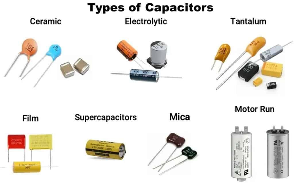
The Major Capacitor Types at a Glance
Before getting into the details of each type, here’s a comparison table that gives you the lay of the land. Use this as a quick-reference when you’re in the middle of a design and need to make a fast decision.
Capacitor Type
Capacitance Range
Voltage Range
Polarized?
Typical ESR
Best For
Ceramic (MLCC)
0.5 pF – 100 µF
6V – 1000V+
No
0.01–0.1 Ω
Decoupling, filtering, high-frequency
Electrolytic (Aluminum)
1 µF – 1 F
4V – 500V
Yes
0.01–10 Ω
Bulk energy storage, power smoothing
Tantalum (Solid)
0.1 µF – 1000 µF
4V – 100V
Yes
0.1–2 Ω
Mid-range bulk, compact designs
Polymer
2.2 µF – 1000 µF
2V – 100V
Yes
0.003–0.1 Ω
Low-ESR bulk, power supplies
Film
100 pF – 100 µF
50V – 2000V+
No
0.001–0.01 Ω
Power electronics, audio, AC circuits
Supercapacitor
0.1 F – 3000 F
2.5V – 6V
No
0.5–50 mΩ
Energy harvesting, regenerative braking
Variable
10 pF – 500 pF
varies
No
varies
RF tuning, oscillators
Ceramic Capacitors: The Workhorses of PCB Design
If you’re designing a board with any digital ICs on it, you are using ceramic capacitors. Probably dozens of them. MLCCs — multilayer ceramic capacitors — account for the largest share of all capacitors manufactured globally, with roughly a trillion pieces produced every year. They’re cheap, small, reliable, and incredibly versatile.
The construction is straightforward: alternating layers of ceramic dielectric and metal electrodes, stacked and fired together. The result is a compact, surface-mount package that works beautifully at high frequencies.
But here’s where it gets interesting — and where a lot of designers make mistakes. Not all ceramic capacitors are the same. The dielectric material determines everything about how the capacitor actually behaves, and the industry codes those materials with a three-character designation system that you need to understand.
Ceramic Dielectric Classes: C0G, X7R, X5R, Y5V, and Z5U Decoded
The EIA standard uses a three-character code to describe ceramic dielectric behavior. The first character indicates the lowest operating temperature. The second character indicates the highest operating temperature. The third character indicates the maximum capacitance change over that temperature range.
Here’s what that looks like in practice:
Code
Temp Range
Max Capacitance Change
Class
Stability Grade
C0G / NP0
-55°C to +85°C
±30 ppm/°C
Class 1
Excellent
X7R
-55°C to +125°C
±15%
Class 2
Good
X5R
-55°C to +85°C
±15%
Class 2
Good
Y5V
-30°C to +85°C
+22% / -82%
Class 2
Poor
Z5U
+10°C to +85°C
+22% / -56%
Class 2
Poor
C0G (also written NP0) is the gold standard for stability. These are Class 1 ceramics — paraelectric materials that do not age, don’t shift significantly with voltage, and hold their value tightly across temperature. If you’re designing timing circuits, oscillator loading, or precision filters, C0G is your material. The tradeoff is size and cost: you can’t pack as much capacitance into a small footprint because the dielectric constant is relatively low.
X7R is probably the most commonly specified capacitor on any modern PCB. It offers a decent temperature range, stays within ±15% across that range, and comes in high capacitance densities. It’s the go-to for general-purpose decoupling. But it ages — typically about 2.5% per decade — and its capacitance drops measurably as you increase the DC bias voltage. On a 0402 package rated at 10V, applying 7V of DC bias might eat 40% of your capacitance. That’s not a spec-sheet footnote. That’s a design-killing gotcha.
X5R behaves similarly to X7R but with a narrower high-temperature limit of +85°C instead of +125°C. Fine for consumer electronics running in controlled environments. Not fine for automotive or industrial boards that see real temperature swings.
Y5V and Z5U are the budget options. Y5V can lose up to 82% of its rated capacitance over its temperature range. These were once common in consumer electronics but are increasingly falling out of favor. If you see Y5V in a BOM today, somebody is cutting corners or the design predates better options being available.
Class 2 Ceramic Capacitors: The Piezoelectric Noise Problem
One thing worth knowing: Class 2 ceramics are ferroelectric, which means they exhibit piezoelectric behavior. When AC signals pass through them, they can vibrate slightly — and that vibration generates audible noise. If you’re designing audio equipment or any circuit where microphonic noise matters, stick with C0G. Class 1 ceramics don’t have this problem.
Electrolytic Capacitors: High Capacitance, Real Tradeoffs
When you need capacitance in the tens-of-microfarads to hundreds-of-microfarads range and can’t fit a bank of ceramics, electrolytic capacitors step in. Aluminum electrolytics are the most common variant. They use a liquid or gel electrolyte to achieve high capacitance in a relatively compact cylindrical or SMD package.
The key limitation everyone knows about: they’re polarized. Connect them backwards and you’re looking at a damaged part at best, an explosion at worst. Always double-check polarity markings on your layout.
Beyond polarity, the real issue with wet aluminum electrolytics is their ESR behavior over time. The liquid electrolyte evaporates gradually, and as it does, ESR creeps up. When ESR rises enough, the capacitor stops doing its job — and in switching power supplies, that’s a common failure mode that can take down an entire board. Running electrolytics at temperatures higher than their rated maximum accelerates this dramatically. A cheap 85°C-rated electrolytic might last 1,000 hours at temperature. Go with a 105°C or 125°C-rated part and you extend that by a significant margin.
For bulk energy storage, power supply output filtering, and applications where you need a large reservoir of charge that can respond to medium-frequency transients, aluminum electrolytics remain the cost-effective choice. Just don’t use them for high-frequency decoupling. Their ESR is too high and their self-resonant frequency too low for that job.
Tantalum Capacitors: Dense, Polarized, and Demanding
Tantalum capacitors offer higher capacitance density than aluminum electrolytics in most package sizes, which makes them popular in space-constrained SMD designs. They use tantalum metal as the anode, with a tantalum pentoxide oxide layer as the dielectric and either manganese dioxide (MnO2) or a conductive polymer as the cathode material.
The MnO2 variant has been the industry workhorse for decades. It’s reliable, it ages well, and MnO2 tantalums with proper design typically only fail during initial infant mortality — after that, they run essentially indefinitely. They’re the preferred choice for military and aerospace applications.
The risk with tantalum capacitors is overvoltage. Unlike most other capacitor types, tantalums can fail catastrophically if you exceed their voltage rating — and the failure mode is thermal runaway. In the worst case, that means fire on your board. Standard practice is to derate tantalum voltage ratings by 50-60%. If a part is rated 10V, design your circuit so it never sees more than 5V across it. This is not optional. It’s a safety margin that experienced engineers take seriously.
Tantalum Type
ESR
Failure Mode
Voltage Derating
Best Application
MnO2 (solid)
0.1–2 Ω
Thermal runaway (rare)
50–60%
Military, aerospace, long-life
Polymer
3–50 mΩ
High DCL (benign)
10–20%
Consumer electronics, power supplies
Polymer Capacitors: The Modern Electrolytic Alternative
Polymer capacitors have quietly become one of the most important capacitor types in modern board design, and if you’re still defaulting to wet electrolytics or MnO2 tantalums for your bulk decoupling, it’s worth reconsidering.
The core technology is simple: replace the liquid or MnO2 electrolyte with a solid conductive polymer. The result is a capacitor with ESR values in the single-digit milliohm range — comparable to ceramics — combined with capacitance values that ceramics can’t match without enormous physical size.
Polymer capacitors don’t dry out. They don’t have the catastrophic overvoltage failure mode of MnO2 tantalums. Their ESR stays stable over temperature and over the life of the part. And in many power supply designs, a single polymer capacitor can replace multiple parallel ceramic capacitors, actually saving board space and reducing cost.
The tradeoffs are real but manageable. Polymer parts have lower voltage ratings than their MnO2 equivalents — typically maxing out around 25-100V depending on the family. They’re also more sensitive to moisture during PCB assembly (most are MSL-3 or higher), so your reflow process needs to handle them correctly. And in high-temperature applications above 85°C, some polymer families begin to degrade. Check the datasheet for the specific temperature rating before committing.
For switching power supply output filters, VRM decoupling, and any application where you need low ESR and high capacitance in a compact footprint, polymer capacitors are often the best choice available.
Film Capacitors: Built for the Heavy Lifting
Film capacitors use a thin sheet of plastic — polyester, polypropylene, polycarbonate, or similar — as the dielectric, with metal foil electrodes on either side. They’re the most stable and lowest-loss capacitors you can buy for general-purpose use.
What makes film capacitors special is their behavior under stress. They don’t age appreciably. Their capacitance stays flat across temperature and voltage. Their ESR is extremely low — often in the microohm to low-milliohm range. And they can handle AC voltages and high currents without complaint.
These characteristics make film capacitors the default choice for power electronics applications: motor drives, inverters, power factor correction circuits, and anywhere you’re dealing with significant voltage and current levels. They’re also the standard in audio crossover networks, where precision and low distortion matter.
Film capacitors typically come in larger physical sizes than ceramics or tantalums, and they cost more per unit. For signal-level decoupling on a digital PCB, they’re overkill. But for power-stage applications, nothing else comes close to their combination of stability, low loss, and long-term reliability.
Film Dielectric Type
Temperature Stability
Voltage Range
Typical Use
Polypropylene (PP)
Excellent
100V – 2000V+
Power electronics, PFC
Polyester (PET/Mylar)
Good
50V – 1000V
General purpose, coupling
Polycarbonate
Very Good
50V – 600V
Precision timing, filters
Supercapacitors: When You Need Energy Storage, Not Just Filtering
Supercapacitors — also called ultracapacitors — operate on a fundamentally different principle than conventional capacitors. They store energy using electrostatic double-layer capacitance at the interface between an electrode and an electrolyte, giving them capacitance values from tenths of a farad all the way up to thousands of farads. That’s several orders of magnitude above what any ceramic or electrolytic can offer.
They can’t replace batteries for long-duration energy storage. Their voltage per cell is low — typically 2.5 to 2.7V — and their energy density is still well below lithium-ion. But they charge and discharge 10 to 100 times faster than batteries, and they can survive hundreds of thousands of charge/discharge cycles without meaningful degradation. That cycle life alone makes them ideal for regenerative braking in electric vehicles, energy recovery in industrial systems, and backup power for applications where a battery would degrade too quickly.
Recent breakthroughs in graphene-based electrode materials are pushing supercapacitor energy densities closer to those of lead-acid batteries, with researchers reporting volumetric energy densities approaching 100 Wh/L. That’s a technology space worth watching as it matures.
Supercapacitors are already showing up in real production systems. Electric buses in China and low-floor trams in Germany use supercapacitor banks for regenerative braking, rapidly recharging at every stop without overhead power lines. In smaller-scale applications, supercapacitors are used as backup power for SRAM and real-time clocks, replacing coin cells in some designs because they can be charged directly from the main power supply and never need to be physically swapped out. The global supercapacitor market was valued at roughly $3.5 billion in 2024 and is growing at over 14% annually, driven primarily by electric vehicle adoption and renewable energy grid stabilization projects.
If you’re designing a board that needs to hold power through a brief outage — say, 30 seconds to a few minutes — and the load is modest, a supercapacitor is worth evaluating against a battery. The charge/discharge efficiency is higher, the cycle life is essentially unlimited compared to any battery chemistry, and the thermal management story is much simpler. Just remember to size the voltage correctly for your application, and add appropriate balancing if you’re stacking cells in series.
Variable Capacitors: Tuning the Old-Fashioned Way
Variable capacitors are exactly what they sound like: capacitors whose value can be adjusted mechanically or electrically. Trimmer capacitors are the small, screwdriver-adjustable type you’ll find on RF modules and oscillator circuits. Tuning capacitors are the larger, rotary-shaft type historically used in radio receivers.
In modern designs, most tuning is done digitally — varactors, switched capacitor arrays, and similar techniques have replaced most mechanical variable capacitors. But trimmers still show up regularly in calibration-sensitive circuits, and understanding how they work is part of any well-rounded RF design education.
Variable Capacitor Type
Capacitance Range
Adjustment Method
Common Use
Trimmer
1 pF – 500 pF
Screwdriver
Oscillator calibration, RF
Tuning (air)
10 pF – 500 pF
Rotary shaft
Legacy radio, test equipment
Varactor (diode)
1 pF – 50 pF
Voltage-controlled
VCO, PLL, synthesizers
Decoupling and Bypass on PCBs: Where Capacitor Type Really Matters
This is where rubber meets road for most board designers. Decoupling capacitors keep the voltage at an IC’s power pin stable during fast switching events. Bypass capacitors route high-frequency noise directly to ground. The terms are often used interchangeably, but they solve subtly different problems.
The general strategy on any digital PCB is layered: you need local high-frequency decoupling right at the IC power pins (100nF ceramics in 0402 or 0603), supported by mid-frequency bulk capacitance (polymer or tantalum, 10-100µF) somewhere nearby, backed by board-level bulk energy storage (electrolytic, 100µF+) near the power input.
Placement matters enormously. The 100nF ceramic should be within 1-2mm of the IC power pin. Every millimeter of trace between the capacitor and the pin adds parasitic inductance, which reduces the capacitor’s effectiveness at exactly the frequencies where you need it most. On multilayer boards, putting bypass capacitors on the bottom layer directly beneath the IC is often the best approach — it minimizes trace length and keeps the loop area small.
For BGAs specifically, place vias right next to the power and ground ball pads, and connect your decoupling capacitors through those vias. The via inductance itself becomes the limiting factor at very high frequencies, so keep your power-ground via pairs as tight as possible.
Recommended Decoupling Capacitor Stack for a Typical Digital Board
Layer
Capacitor Type
Value
Package
Role
Local (per IC pin)
Ceramic C0G or X7R
100 nF
0402 / 0603
High-frequency noise filtering
Mid-range (per IC)
Polymer or Tantalum
10–22 µF
0805 / 1206
Mid-frequency bulk
Board-level bulk
Electrolytic or Polymer
100–470 µF
SMD can
Low-frequency energy reservoir
How to Choose the Right Capacitor: A Decision Framework
When you’re staring at a schematic and need to pick a capacitor, run through these questions in order. The answers will narrow your selection fast.
What frequency range matters? High-frequency applications (above 1 MHz) demand low-ESR, low-inductance parts — ceramics are your primary choice. Low-frequency power smoothing can tolerate higher ESR — electrolytics are fine here.
What voltage will the capacitor actually see? Not the supply voltage. The actual voltage, including any transients, ripple, or bias. Then apply appropriate derating: 20% for ceramics, 50%+ for MnO2 tantalums, 10-20% for polymer tantalums.
Does polarity matter? If the signal or voltage can reverse, you need a non-polarized type. Ceramics, film, and variable capacitors are all non-polarized. Electrolytics, tantalums, and polymer electrolytics are not.
How stable does the capacitance need to be? Precision timing and filtering need C0G. General decoupling is fine with X7R. Bulk energy storage doesn’t care much about ±20% tolerance.
What’s the operating temperature range? Consumer indoor products can get away with X5R or even Y5V. Automotive, industrial, and military designs need X7R at minimum, and often C0G for critical functions.
How long does this board need to last? Wet electrolytics have finite life due to electrolyte evaporation. If your product is expected to run for 10+ years in a warm environment, polymer or solid-state alternatives are worth the premium.
What does the IC datasheet actually say? This is the one step that saves you the most debugging time. Most IC manufacturers include recommended bypass capacitor values, types, and placement guidance in their datasheets. If Texas Instruments tells you to put a 100nF ceramic and a 10µF ceramic on the VDD pin of their microcontroller, there’s a reason — they’ve already done the characterization work. Start there, then adjust based on your specific board layout and power delivery network topology.
Are you running multiple voltage rails? If so, keep each rail’s decoupling independent. Don’t daisy-chain your bypass capacitors across different voltage domains. A noise event on a 1.8V rail should not have a path to couple into your 3.3V analog supply. Proper separation of power domains is one of the first things that gets checked in any EMC pre-compliance test, and capacitor selection plays a direct role in how well you achieve that isolation.
Frequently Asked Questions About Capacitors
Q: Can I replace a tantalum capacitor with a ceramic one on my board? A: Sometimes, but not blindly. Ceramics lose significant capacitance with DC bias voltage — a 10µF X7R in a small package might actually deliver only 3-4µF at the bias voltage in your circuit. If you’re replacing a tantalum, calculate the effective capacitance of the ceramic at your actual operating voltage, and you may need to go to a larger package or higher nominal value to match. Also remember that tantalums are polarized and ceramics are not — the polarity markings on your board are now irrelevant, which simplifies assembly but removes a built-in orientation check.
Q: Why do my ceramic capacitors seem to lose value over time? A: Class 2 ceramics (X7R, X5R, Y5V, Z5U) experience ferroelectric aging. The capacitance gradually decreases after the component is manufactured, particularly if it’s stored at room temperature without being charged. The aging rate for X7R is typically around 2.5% per decade. This aging can be reversed by heating the capacitor above its Curie point — which is essentially what happens during reflow soldering. So a freshly soldered board has “de-aged” capacitors, but they’ll start aging again from that point forward.
Q: What does ESR actually mean in practice, and why should I care? A: ESR is the total internal resistance of a capacitor — it includes the resistance of the leads, electrodes, electrolyte, and dielectric losses all lumped into one number. In practice, high ESR means the capacitor wastes energy as heat when current flows through it, it can’t deliver or absorb current as quickly, and it introduces voltage ripple. In switching power supplies, high ESR on the output capacitor is one of the most common causes of instability and failure. For power-critical applications, always check the ESR spec — not just the capacitance.
Q: Is it safe to use capacitors right up to their rated voltage? A: Technically within spec, but not a good practice. Every capacitor type benefits from voltage derating — using it at less than its maximum rated voltage extends life, improves reliability, and reduces stress. The amount of derating depends on the type: 20% is reasonable for ceramics, 50%+ for MnO2 tantalums, and 10-20% for polymer types. Military and aerospace standards are often even more conservative than these numbers.
Q: What’s the difference between a decoupling capacitor and a bypass capacitor? A: They’re closely related but technically distinct. Decoupling capacitors isolate one part of a circuit from another on a shared power rail — they reduce the noise coupling between an IC and the rest of the power distribution network. Bypass capacitors specifically route high-frequency noise to ground, providing a low-impedance AC path. In practice, the same physical capacitor often does both jobs simultaneously, and the terms get used interchangeably. The important thing is understanding what the capacitor needs to accomplish electrically, and choosing its type, value, and placement accordingly.
Useful Resources and Databases for Capacitor Selection
These are the references and tools that actually get used in day-to-day design work. Bookmark the datasheets and databases — they save more time than any textbook.
Capacitor selection is one of those skills that looks simple from the outside and reveals its depth the moment you start designing real boards. The spec sheet tells you the capacitance and voltage rating. The datasheet tells you the ESR, the temperature behavior, and the aging curve. But knowing which of those numbers actually matter for your specific circuit — and which ones will bite you if you ignore them — that comes from understanding the physics behind each type and the real-world failure modes that come with it.
Ceramics are your high-frequency workhorses. Electrolytics are your bulk reservoirs. Tantalums and polymers fill the gap in between with increasingly good performance from polymer types. Film capacitors handle the power-stage heavy lifting. Supercapacitors are a fast-growing category for energy storage where batteries are either overkill or too slow.
Pick the right type for the job, derate your voltages appropriately, place your decoupling capacitors close to the pins that need them, and verify your assumptions with datasheets from the actual manufacturer — not just the generic specs. That’s the short version of everything this guide covers, and it’s the foundation of capacitor selection that will serve you well regardless of what you’re building.
The best engineers don’t memorize every capacitor part number. They understand the tradeoffs deeply enough to make fast, confident decisions when it matters — and to know when to slow down and double-check. This guide is meant to get you there.
Inquire: Call 0086-755-23203480, or reach out via the form below/your sales contact to discuss our design, manufacturing, and assembly capabilities.
Quote: Email your PCB files to Sales@pcbsync.com (Preferred for large files) or submit online. We will contact you promptly. Please ensure your email is correct.
Notes: For PCB fabrication, we require PCB design file in Gerber RS-274X format (most preferred), *.PCB/DDB (Protel, inform your program version) format or *.BRD (Eagle) format. For PCB assembly, we require PCB design file in above mentioned format, drilling file and BOM. Click to download BOM template To avoid file missing, please include all files into one folder and compress it into .zip or .rar format.


