Inquire: Call 0086-755-23203480, or reach out via the form below/your sales contact to discuss our design, manufacturing, and assembly capabilities.
Quote: Email your PCB files to Sales@pcbsync.com (Preferred for large files) or submit online. We will contact you promptly. Please ensure your email is correct.
Notes: For PCB fabrication, we require PCB design file in Gerber RS-274X format (most preferred), *.PCB/DDB (Protel, inform your program version) format or *.BRD (Eagle) format. For PCB assembly, we require PCB design file in above mentioned format, drilling file and BOM. Click to download BOM template To avoid file missing, please include all files into one folder and compress it into .zip or .rar format.
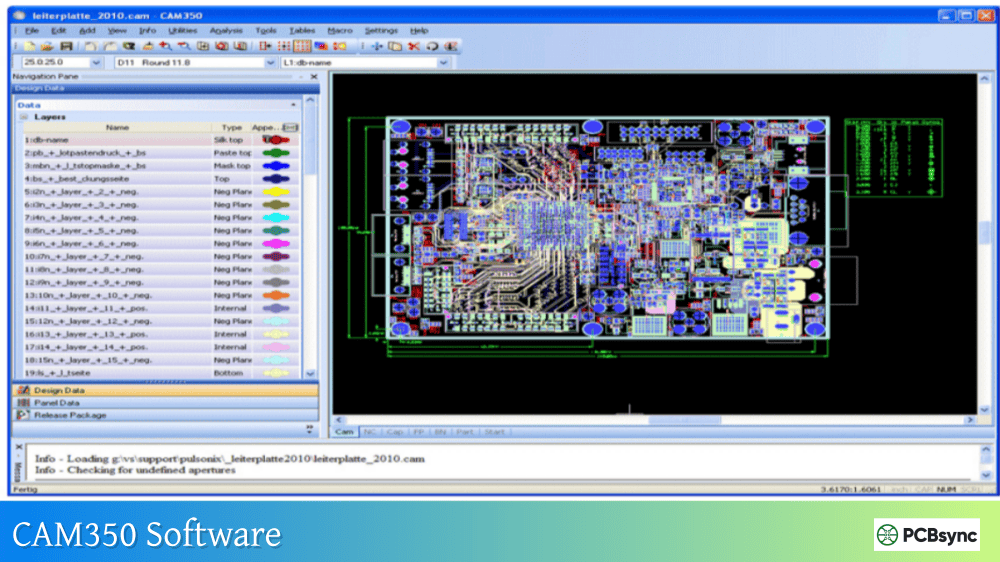
CAM350 Software: The Complete Guide to PCB CAM Engineering [2026]
If you’ve spent any time in a PCB fabrication environment, you’ve almost certainly encountered CAM350. It’s become the de facto standard for preparing design files before they hit the production floor, and for good reason. After years of working with various CAM tools, I can tell you that CAM350 software delivers a combination of verification capabilities, optimization features, and output generation that few competitors match.
This guide covers everything CAM engineers and PCB designers need to know about Downstream CAM350, from core functionality and version differences to practical workflows that actually save time in production. Whether you’re evaluating the software for your fab shop or trying to get more out of your existing license, this comprehensive walkthrough has you covered.
CAM350 is a computer-aided manufacturing software developed by DownStream Technologies (now part of Siemens) specifically for PCB fabrication preparation. The software sits between design completion and actual manufacturing, serving as the critical checkpoint where design intent meets production reality.
Think of it this way: your PCB design tool creates the blueprint, but CAM 350 makes sure that blueprint can actually be built without defects, delays, or costly rework. It handles everything from importing design data and running DFM checks to generating optimized drill files and creating production panels.
The software addresses several critical pain points in PCB manufacturing:
3D visualization shows fabricators exactly what’s expected
For PCB fabricators, CAM350 software reduces the risk of scrap boards, production delays, and customer complaints. For design engineers, it provides confidence that their designs will manufacture correctly the first time.
CAM350 Software Versions and Configurations
Understanding the different CAM350 configurations helps you select the right toolset for your needs. DownStream offers several tiers, each building on the previous one’s capabilities.
Current Release: Valor CAM350 Version 15.2
The latest Downstream CAM350 release (Version 15.2) introduced several significant enhancements that production engineers have been requesting:
New Stencil Design Tool Kit: Creates PCB paste mask stencils directly from imported manufacturing data. You can convert photo plotting flashes and pads into stencil patterns, either automatically or by selecting specific footprints from a library. This alone has saved our team hours of back-and-forth with stencil vendors.
Enhanced Netlist Compare: Improved error exploration features make tracking down connectivity problems faster. The graphical error representation lets you visualize issues rather than parsing through text reports.
Design Compare Improvements: Now includes automated alignment of comparison designs and simplified layer mapping. Design Compare is also available as a licensed add-on for lower-tier configurations.
Cadence Allegro Integration: Direct pass-through of design data including constraints, rules areas, and back annotation of error markers from the Allegro menu system.
Full DFM analysis, Design Analyzer, rigid-flex support, stencil designer
Complete fabrication analysis
FabFactory
Advanced NC editor, advanced panel editor
Full PCB factory operations
Most fabrication shops I’ve worked with run at least the 160 or 195 level. The viewer configuration (070) works for design engineers who just need to check Gerber output, but serious CAM work requires the editing and analysis capabilities of higher tiers.
Core CAM350 Features and Capabilities
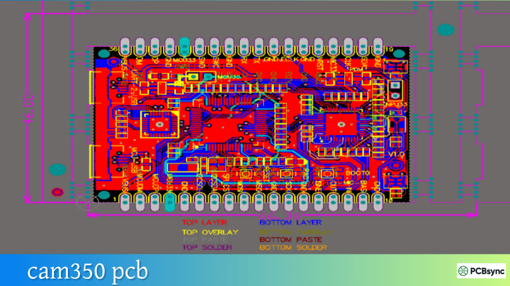
Data Import and Format Support
One of CAM350’s strongest advantages is its broad format compatibility. The software accepts data from virtually every PCB design tool through standard formats:
Import Formats:
Gerber (RS-274D, RS-274X, Fire9000, Barco DPF)
ODB++ (intelligent format with full design data)
IPC-2581 (open standard alternative to ODB++)
Excellon and Sieb & Meyer (NC drill/mill)
DXF, GenCAD, HPGL
IPC-D-356 netlists
Export Formats:
All import formats plus PADS ASCII
3D PDF for documentation and visualization
Various flying probe tester formats (Probot, ATG, Integri-test)
The Auto-Import feature in CAM 350 automatically recognizes file types and assigns layers appropriately, which cuts setup time dramatically when processing customer data. Manual import remains available for non-standard naming conventions or special requirements.
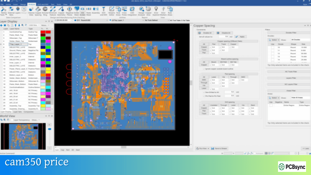
Design Rule Checking (DRC) and DFM Analysis
The DFM capabilities in CAM350 software go well beyond basic clearance checks. The Streams methodology lets you define sequences of checks to run automatically:
Fabrication Checks:
Minimum trace width and spacing
Annular ring analysis
Acid trap detection
Copper sliver identification
Soldermask sliver detection
Thermal relief validation
Assembly Checks:
Solder bridge potential
Component spacing
Paste mask coverage
Silkscreen violations
Electrical Verification:
Netlist extraction from Gerber
Comparison against IPC-D-356 reference netlist
Open and short detection
Net continuity validation
The Stream Rules Editor allows you to save check configurations and apply them consistently across jobs. Define your factory’s capabilities once, then verify every incoming design against those parameters automatically.
Netlist Comparison and Verification
Netlist compare is arguably the most critical function in CAM350 for catching errors that would otherwise reach production. Here’s how the workflow typically runs:
Import Gerber layers and drill data
Extract CAM netlist from the imported data (Utilities → Netlist Extract)
Import reference IPC-D-356 netlist from the original CAD system
The latest versions added graphical error display, so you can see exactly where connectivity problems exist rather than just reading a list of affected nets. Crossprobing with Cadence Allegro, PADS, or Xpedition lets you jump directly to error locations in the source design tool.
Panelization and Step-and-Repeat
CAM350 includes powerful panelization tools that optimize material usage while meeting production requirements:
Panel Wizard Features:
Automatic array calculation based on panel size and board dimensions
Rotation optimization to minimize waste
Fiducial placement for SMT alignment
V-score and mill tab definition
Breakaway tab positioning
Manual Panel Design:
Merge multiple designs into a single panel
Custom spacing and arrangement
Mixed board panelization
Add tooling holes, coupons, and borders
The Fast Array function generates panels quickly for standard layouts, while the Advanced Panel Editor handles complex requirements like rigid-flex separation or mixed-technology panels.
NC Editing for Drill and Mill Data
The NC Editor in CAM350 software creates and modifies drill and routing files:
Drill Operations:
Tool table management
Hit optimization for faster drilling
Slot creation
Tool sequencing
Mill Operations:
Board outline routing
Internal cutouts
Tab creation for panel separation
Depth-controlled milling for rigid-flex
You can convert Gerber content to NC data and vice versa, which proves useful when original drill files are missing or corrupted.
3D Visualization and Stack-up Definition
The 3D visualization introduced in CAM350 Version 14 and enhanced in subsequent releases provides a virtual model of the finished PCB:
3D Features:
Layer-by-layer visualization of copper, mask, and silk
Cross-section views through the board stackup
Realistic rendering with materials and colors
3D PDF export for sharing with customers and assembly partners
The Stack-up Visualizer lets you define layer materials, thicknesses, and dielectric properties. This information feeds into impedance calculations and manufacturing documentation.
CAM350 Workflow: From Import to Production Output
Let me walk through a typical CAM 350 workflow that mirrors what happens in most fabrication shops:
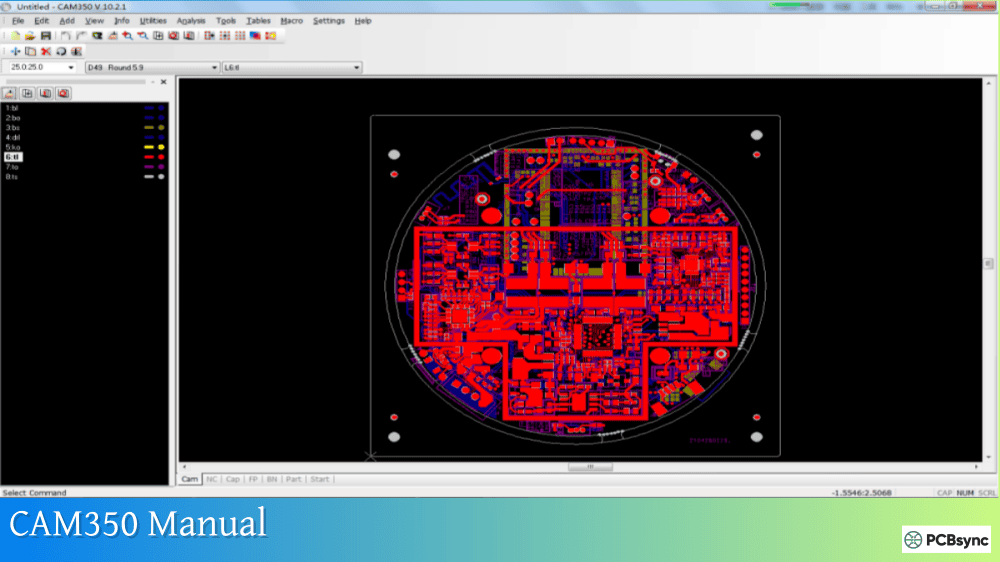
Step 1: Data Import and Initial Review
File → Import → Auto ImportSelect directory containing Gerber and drill filesReview layer assignments in import dialogClick Finish to complete import
After import, visually inspect each layer using the layer visibility controls. Check that:
All expected layers are present
Layer polarity (positive/negative) is correct
Board outline matches specifications
Drill sizes appear reasonable
Step 2: Drill Data Import and Verification
Drill data often comes separately:
File → Import → Drill DataSelect drill file (typically .drl or .exc extension)Verify tool table matches documentationMap tools to correct sizes if needed
Use Analysis → Copper Area to check that drill hits land on pads as expected. Missing or misaligned holes show up immediately in this view.
Step 3: DFM Analysis Execution
Run your standard DFM stream:
Analysis → Streams → Select your saved streamClick RunReview results in Error Explorer
Address each error category systematically. Some common findings and resolutions:
CAM350 competes with several other CAM tools in the market. Here’s how they compare:
Feature
CAM350
Genesis 2000
UCAM
InCAM
Market Position
Industry standard
Popular in Asia
European market
Advanced fabrication
DFM Depth
Comprehensive
Very comprehensive
Good
Extensive
Ease of Use
Moderate learning curve
Steeper learning curve
Moderate
Moderate
Scripting/Automation
VB Script support
Strong automation
Good
Excellent
Price Point
Mid-high
High
Mid
High
3D Visualization
Yes
Yes
Limited
Yes
CAD Integration
Good (Allegro, PADS)
Good
Moderate
Good
Genesis 2000 (now part of Orbotech/Frontline) holds the largest market share in high-volume Asian fabrication facilities. CAM350 software tends to dominate in North American and European shops, particularly among mid-size fabricators. The choice often comes down to existing tool investments and regional support availability.
Licensing Options and Pricing
Downstream CAM350 offers flexible licensing to accommodate different organizational needs:
Perpetual License: One-time purchase with annual maintenance fees for updates and support. Best for organizations with stable, long-term CAM requirements.
Subscription License: Annual or monthly payment with lower upfront cost. Includes all updates during subscription period. Introduced in Version 15 to make DFM accessible to more engineers.
Node-Locked vs. Floating: Node-locked licenses tie to a specific computer. Floating licenses allow concurrent use across a network up to the purchased seat count.
Pricing starts around $500 USD for entry-level configurations and scales significantly for full DFM capability. Contact DownStream or authorized resellers for current quotes, as pricing depends on configuration, license type, and volume.
Free Trial Availability
DownStream offers evaluation licenses for prospective customers. The trial provides full functionality for a limited period, allowing you to test workflows with actual production data before purchase.
CAM350 Integration with Design Tools
CAM 350 connects with leading PCB design platforms through various interfaces:
Cadence Allegro and OrCAD Integration
Version 15 introduced direct integration with Cadence tools:
Launch CAM350 from Allegro menu
Pass complete design data including constraints
Crossprobe errors back to source design
Back-annotate error markers
PADS and Xpedition Integration
The crossprobing feature works bidirectionally:
Select element in CAM350, highlight in PCB tool
Select element in PCB tool, highlight in CAM350
Navigate directly to DFM error locations
BluePrint-PCB Integration
DownStream’s documentation tool works closely with CAM350:
Create assembly panels in BluePrint
Pass to CAM350 for manufacturing outputs
Generate coordinated documentation and production files
CAM350 supports all major PCB manufacturing formats including Gerber RS-274D and RS-274X, ODB++, IPC-2581, Excellon drill, Sieb & Meyer, DXF, GenCAD, and HPGL. The software can export to these same formats plus PADS ASCII, 3D PDF, and various test equipment formats. This broad compatibility means you can accept data from virtually any PCB design tool and output files for any fabrication or test system.
Is CAM350 suitable for HDI and advanced technology boards?
Yes, CAM350 software handles HDI, rigid-flex, and advanced technology boards. The DFM analysis includes checks specific to these technologies, such as blind/buried via validation, laser drill requirements, and flex layer handling. The rigid-flex support added in recent versions addresses the unique challenges of combined rigid and flexible sections. For very advanced technologies, ensure you’re running a recent version with appropriate license tier.
How does CAM350 compare to free Gerber viewers?
Free Gerber viewers (like GerbView or online tools) work fine for basic file inspection, but CAM 350 provides far more capability. The key differences include DFM analysis to catch manufacturing issues, netlist verification to confirm electrical integrity, panelization tools for production optimization, and NC editing for drill/mill data. If you’re just checking that files look correct, a free viewer works. If you’re preparing files for actual fabrication, CAM350 or similar professional CAM software is essential.
Can CAM350 convert Gerber back to native CAD format?
CAM350 includes reverse engineering features that convert Gerber data back into a more intelligent format with recognized traces, vias, padstacks, and nets. However, this isn’t a perfect recreation of original CAD data. It works well for modifying legacy designs or recovering from lost source files, but the result requires verification and may need manual cleanup. The feature is most useful for creating editable files when originals are unavailable.
What training is available for learning CAM350?
DownStream provides multiple training options: live online classes, webinars, on-site training, and comprehensive built-in documentation. The software also includes tutorial content for new users. Many fabrication shops train CAM engineers internally using a combination of vendor resources and hands-on practice with actual production jobs. The learning curve is moderate; engineers with PCB background typically become productive within a few weeks.
Conclusion
CAM350 has earned its position as the industry standard for PCB CAM engineering through consistent development, broad format support, and deep fabrication analysis capabilities. Whether you’re running a high-volume fabrication shop or preparing occasional designs for outside manufacturing, the software provides the verification and optimization tools needed to get boards built right the first time.
The recent Version 15 improvements, particularly the Stencil Design Tool Kit and enhanced netlist comparison, demonstrate DownStream’s continued commitment to addressing real production challenges. The introduction of subscription pricing also makes Downstream CAM350 accessible to smaller organizations that couldn’t justify perpetual license costs.
For anyone serious about PCB manufacturing quality, investing time in learning CAM 350 pays dividends through reduced scrap, faster turnaround, and fewer customer complaints. The software won’t eliminate all manufacturing problems, but it catches the vast majority of issues that would otherwise surface on the production floor, where fixes are far more expensive.
Inquire: Call 0086-755-23203480, or reach out via the form below/your sales contact to discuss our design, manufacturing, and assembly capabilities.
Quote: Email your PCB files to Sales@pcbsync.com (Preferred for large files) or submit online. We will contact you promptly. Please ensure your email is correct.
Notes: For PCB fabrication, we require PCB design file in Gerber RS-274X format (most preferred), *.PCB/DDB (Protel, inform your program version) format or *.BRD (Eagle) format. For PCB assembly, we require PCB design file in above mentioned format, drilling file and BOM. Click to download BOM template To avoid file missing, please include all files into one folder and compress it into .zip or .rar format.


