Inquire: Call 0086-755-23203480, or reach out via the form below/your sales contact to discuss our design, manufacturing, and assembly capabilities.
Quote: Email your PCB files to Sales@pcbsync.com (Preferred for large files) or submit online. We will contact you promptly. Please ensure your email is correct.
Notes: For PCB fabrication, we require PCB design file in Gerber RS-274X format (most preferred), *.PCB/DDB (Protel, inform your program version) format or *.BRD (Eagle) format. For PCB assembly, we require PCB design file in above mentioned format, drilling file and BOM. Click to download BOM template To avoid file missing, please include all files into one folder and compress it into .zip or .rar format.
If you’ve been designing printed circuit boards for high-reliability applications, you’ve probably encountered the term “CAF resistance” in laminate datasheets or design specifications. But understanding what CAF resistance actually means—and why it matters—can save you from costly field failures that damage both products and reputations.
I’ve spent years troubleshooting PCB failures across automotive, industrial, and telecom applications. Conductive Anodic Filament (CAF) failures rank among the most frustrating to diagnose because they often appear intermittently and develop slowly over the product’s lifetime. This guide breaks down everything you need to know about CAF resistance, from the electrochemistry behind it to practical design and material choices that prevent it.
Understanding CAF: The Hidden Threat Inside Your PCB
Conductive Anodic Filament, commonly called CAF, represents one of the most insidious failure mechanisms in modern printed circuit boards. Unlike visible defects caught during inspection, CAF develops internally between layers of your multilayer board—completely hidden from view until something stops working.
What Exactly is Conductive Anodic Filament?
CAF is essentially an electrochemical migration process where copper ions travel from a positively charged conductor (anode) to a negatively charged conductor (cathode) through the PCB substrate. This migration creates a metallic filament that progressively reduces the insulation resistance between those conductors.
Think of it this way: your PCB laminate contains woven glass fibers embedded in epoxy resin. When moisture seeps into microscopic gaps at the glass-resin interface—gaps that may result from thermal stress, drilling damage, or poor lamination—an electrochemical cell forms. Given sufficient voltage bias and humidity, copper dissolves at the anode, migrates along these pathways, and deposits at the cathode.
The result? A conductive bridge where none should exist. Depending on severity, this manifests as increased leakage current, intermittent shorts, or complete electrical failure.
The Two-Stage CAF Formation Process
Understanding CAF formation helps engineers target prevention strategies effectively. The process occurs in two distinct stages:
Stage One: Pathway Degradation
The first stage involves degradation of the glass-resin interface within your laminate. This creates microscopic channels that can hold moisture and support ionic transport. Contributing factors include thermal cycling stresses, aggressive drilling that cracks resin around holes, incomplete resin curing during lamination, and residual contamination from manufacturing processes.
The encouraging news here is that Stage One remains largely reversible. Baking boards to drive out moisture can temporarily restore insulation resistance. However, this doesn’t eliminate the underlying vulnerability—it just resets the clock.
Stage Two: Filament Growth
Once pathways exist and moisture accumulates, electrochemical reactions begin. Copper oxidizes at the anode, forming Cu+ and Cu2+ ions. These ions migrate through the moisture-laden pathway toward the cathode, where they reduce back to metallic copper. Over time, this deposited copper extends from cathode toward anode, eventually forming a continuous conductive filament.
Stage Two represents irreversible damage. Once a filament bridges two conductors, no amount of baking fixes the problem—the board requires replacement or rework.
Why CAF Resistance Matters More Than Ever
Several industry trends have amplified CAF concerns over the past decade, making CAF resistance a critical consideration for virtually any application beyond basic consumer electronics.
Shrinking Geometries and Higher Densities
Modern PCB designs pack increasingly dense circuitry onto smaller boards. Via-to-via spacing that once measured 1mm or more now routinely drops below 0.5mm in high-density interconnect (HDI) designs. Since CAF propagation speed depends partly on the distance between conductors, tighter spacing means failures can develop faster.
Lead-Free Soldering Temperatures
The transition to lead-free assembly introduced peak reflow temperatures 30-40°C higher than traditional tin-lead processes. These elevated temperatures stress laminate materials more severely, potentially damaging glass-resin interfaces and creating CAF-susceptible pathways during assembly.
Harsh Operating Environments
Electronics now operate in environments that would have been considered extreme a generation ago. Automotive under-hood applications routinely see temperatures from -40°C to +150°C combined with high humidity. Industrial IoT devices deploy outdoors. Medical implants must function reliably for years inside the human body.
Each of these environments combines the moisture and temperature factors that accelerate CAF formation.
Longer Service Life Requirements
Consumer electronics might tolerate a few years of operation before replacement, but automotive electronics must function reliably for 15+ years. Aerospace and defense applications demand even longer operational lifetimes. CAF failures that might take a decade to manifest now fall within expected product lifespans.
Key Factors Affecting CAF Resistance
Understanding which variables influence CAF susceptibility helps engineers make informed decisions during design and material selection.
Factor
Impact on CAF Risk
Mitigation Approach
Via-to-Via Spacing
Closer spacing increases risk
Maximize spacing where possible; minimum 0.5mm recommended for high-reliability applications
Voltage Bias
Higher voltage accelerates migration
Separate high-voltage nets from ground; consider voltage levels in placement
Humidity Exposure
Moisture enables electrochemistry
Conformal coating; controlled storage; hermetic sealing for critical applications
Glass Weave Orientation
CAF follows fiber direction
Rotate via patterns 45° relative to weave; avoid aligning adjacent vias with warp/weft
Laminate Material
Base resin chemistry affects resistance
Specify high-Tg, CAF-resistant materials; phenolic-cured systems outperform DICY
Drilling Quality
Rough holes damage resin-glass bonds
Optimize drill parameters; ensure proper desmear
Reflow Cycles
Each thermal cycle adds stress
Minimize assembly passes; control peak temperatures
Material Selection for Enhanced CAF Resistance
Not all FR-4 materials provide equal CAF resistance. The resin system, glass treatment, and curing chemistry all influence performance.
Resin Chemistry Matters
Standard dicyandiamide (DICY)-cured epoxies offer moderate CAF resistance suitable for many applications. However, phenolic-cured epoxy systems demonstrate significantly better long-term performance, particularly at elevated voltage gradients. Research from Isola and other laminate manufacturers shows phenolic systems maintaining insulation resistance longer under identical test conditions.
Glass Transition Temperature (Tg)
Higher-Tg materials generally provide better CAF resistance because they maintain mechanical stability across wider temperature ranges. When the operating temperature approaches or exceeds Tg, resin softens and glass-resin bonds become more susceptible to degradation. For applications facing lead-free assembly and elevated operating temperatures, consider materials with Tg above 170°C.
CAF-Resistant Laminates
Major manufacturers now offer laminates specifically formulated for improved CAF resistance. These typically combine optimized resin chemistry with treated glass fabrics that promote stronger fiber-resin bonding. While these materials cost 20-50% more than standard FR-4, that premium often represents just 1-5% of total PCBA cost—inexpensive insurance against field failures.
Material Type
Typical Tg (°C)
CAF Resistance
Best Applications
Standard DICY FR-4
130-140
Moderate
Consumer electronics, low-voltage applications
High-Tg DICY FR-4
170-180
Good
Industrial, telecom, some automotive
Phenolic-Cured FR-4
170-180
Very Good
Automotive, aerospace, high-voltage
CAF-Resistant Laminate
180-200+
Excellent
Safety-critical, long-life applications
Polyimide
250+
Excellent
Aerospace, military, extreme environments
BT/Epoxy
180-200
Very Good
High-density packaging, RF applications
Design Strategies to Improve CAF Resistance
Smart design practices significantly reduce CAF risk without requiring exotic materials or adding cost.
Via Placement and Orientation
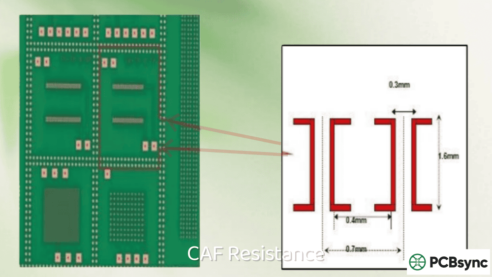
The glass fabric in FR-4 has a woven structure with warp and weft directions. CAF tends to propagate along glass fibers because the fiber-resin interface provides the path of least resistance for ion migration. When adjacent vias carrying different potentials align with the weave direction, they present an ideal setup for CAF formation.
Practical solutions include:
Rotating via pairs by 45 degrees relative to board edges disrupts alignment with the glass weave. This forces any potential CAF pathway to cross multiple fiber intersections, significantly slowing propagation.
Staggering vias between layers rather than stacking them directly prevents creating straight-line paths through the Z-axis. While HDI designs often require stacked microvias for other reasons, full-depth via pairs should avoid perfect alignment when possible.
Increasing spacing between voltage and ground vias remains the most direct countermeasure. Every additional 0.1mm of separation buys meaningful protection. Where layout constraints permit, target 0.75mm minimum for via pairs at different potentials.
Handling High-Voltage Sections
Applications involving voltages above 48V require extra attention. The electric field strength between conductors drives migration rate, so higher voltages demand greater separation and careful material choices.
Space high-voltage nets further apart on inner layers. Consider dedicated layer pairs for high-voltage routing with generous clearances to other circuitry.
Avoid long parallel runs between opposite potentials. When routing must follow similar paths, increase separation or insert grounded shields between critical nets.
Follow IPC-2221 guidelines as a starting point, but recognize that these represent minimums. For safety-critical applications, consult with your laminate supplier about appropriate clearances for your specific material and operating conditions.
Teardrops and Pad Design
Adding teardrops where traces meet pads and vias reduces stress concentrations during drilling and thermal cycling. This seemingly minor design feature smooths the copper transition, reducing resin stress that could create micro-cracks—the very cracks that seed CAF formation.
Delete non-functional pads on inner layers but maintain design-rule spacing as if pads were present. This increases copper-to-copper distance without changing the board’s logical connectivity, directly reducing CAF risk.
Design gets boards halfway to CAF resistance. Manufacturing quality completes the job.
Drilling Optimization
Drilling creates the holes where CAF most commonly initiates. Aggressive parameters that prioritize speed over quality can damage the resin-glass interface around each hole.
Critical drilling parameters include:
Spindle speed and feed rate must balance productivity against hole quality. Excessive speed generates heat that damages resin; insufficient speed may cause fiber pull-out. Your fabricator should optimize these for each laminate type.
Drill bit condition dramatically affects hole quality. Worn bits tear fibers rather than cutting cleanly, leaving damaged resin-glass interfaces around the hole wall.
Desmear processing removes resin smear from drilling but must not be overly aggressive. Excessive desmear can attack the glass-resin interface itself, counterproductively creating the pathways we’re trying to prevent.
Lamination Quality
Proper lamination ensures resin fully wets glass fibers without voids or dry spots. These manufacturing defects create pre-existing pathways that can shortcut CAF formation.
Temperature, pressure, and time profiles must be optimized for each material system. Insufficient curing leaves reactive groups in the resin that may later promote degradation. Excessive processing can damage glass treatments intended to promote fiber-resin bonding.
Cleanliness and Contamination Control
Ionic contamination provides the chemistry that drives electrochemical migration. Sources include plating bath residues, flux residues, fingerprints, and environmental contaminants.
Ion chromatography testing quantifies specific ionic species on board surfaces. While the industry traditionally relied on ROSE (Resistivity of Solvent Extract) testing for cleanliness verification, IC testing provides more actionable data about specific contaminants.
Proper rinsing after each wet process step removes process chemicals before they can leave residues. Attention to DI water quality and rinse times pays dividends in long-term reliability.
CAF Resistance Testing Methods
How do you verify that your boards will resist CAF formation over their intended lifetime? Industry-standard testing provides the answer.
IPC-TM-650 Method 2.6.25
This test method specifically evaluates propensity for CAF growth. Test samples undergo extended exposure to high temperature (85°C), high humidity (85% RH), and applied bias voltage while insulation resistance is monitored.
Test Parameter
Standard Condition
High-Voltage Automotive
Temperature
85°C
85°C
Relative Humidity
85% RH
85% RH
Bias Voltage
10-100V DC
100-1000V DC
Duration
596 hours
596-1000 hours
Pass Criteria
IR > 10⁷ Ω
IR > 10⁷ Ω
The 596-hour duration (approximately 25 days) accelerates failure mechanisms that might take years to manifest in the field. Resistance measurements taken throughout the test reveal any degradation trends.
Standard Test Coupons
IPC has developed standardized coupon designs for consistent CAF testing:
IPC-9253 evaluates X-Y axis CAF between plated through holes and includes provisions for press-fit connector testing.
IPC-9254 adds Z-axis testing capability for layer-to-layer evaluation.
IPC-9255 and IPC-9256 extend the test matrix with additional feature combinations.
These standardized coupons ensure comparable results across laboratories and suppliers. When qualifying materials or processes, specify which coupon design applies to your application.
Failure Analysis Techniques
When CAF testing reveals failures—or field returns suggest CAF as a cause—several analytical techniques can confirm and characterize the problem.
Cross-sectioning through the failure region under microscopy often reveals the filament directly. The conductive path typically follows glass fiber interfaces and appears as a dark or metallic trace between conductors.
Scanning Electron Microscopy (SEM) with energy-dispersive spectroscopy (EDS) identifies the elemental composition of filaments, confirming copper migration and ruling out other failure mechanisms.
X-ray Photoelectron Spectroscopy (XPS) provides even more detailed chemical analysis when needed.
Focused Ion Beam (FIB) techniques can prepare cross-sections without mechanical polishing artifacts, valuable for analyzing delicate failure sites.
Industry Applications Demanding High CAF Resistance
Certain market segments have driven much of the focus on CAF resistance due to their combination of harsh environments, long service lives, and high reliability requirements.
Automotive Electronics
Under-hood applications combine temperature extremes, humidity exposure, and long operational lifetimes—a perfect storm for CAF. Electronic Control Units (ECUs), power electronics, and safety-critical systems all require careful attention to CAF resistance.
Automotive testing often extends beyond standard conditions. Temperature-Humidity-Bias (THB) testing at voltages up to 500V or even 1000V reflects real operating conditions in electric and hybrid vehicles where high-voltage battery systems create substantial electric fields within the PCB.
Aerospace and Defense
Aircraft electronics experience pressure altitude cycling that can pump moisture into and out of laminate materials. Combined with temperature extremes and very long service requirements, aerospace applications demand the highest levels of CAF resistance.
Military specifications typically require CAF-resistant materials and rigorous testing as baseline requirements rather than options.
Medical Devices
Implantable medical devices must function for years inside the human body, surrounded by warm, saline environments. While hermetic sealing provides primary moisture protection, any moisture ingress creates conditions favorable to CAF. Cardiac devices, neurostimulators, and implantable drug pumps all require CAF-resistant construction.
Industrial IoT and Infrastructure
Telecommunications infrastructure, industrial sensors, and smart grid equipment often deploy in outdoor or minimally controlled environments for decades. These applications increasingly specify CAF-resistant materials as standard practice.
Common Misconceptions About CAF Resistance
After years of working with CAF issues, I’ve encountered several persistent misconceptions worth addressing.
“Conformal Coating Solves CAF Problems”
Conformal coating protects board surfaces from environmental moisture and contamination—valuable benefits. However, CAF primarily develops inside the board, along internal glass-resin interfaces. External coating cannot prevent internal moisture that entered during manufacturing or through the board edges from causing CAF.
Coating complements proper material selection and design practice but doesn’t replace them.
“CAF Only Affects High-Voltage Applications”
While higher voltages accelerate CAF formation, even 5V logic circuits can develop CAF failures given sufficient time, tight spacing, and moisture exposure. The failure timeline extends with lower voltage, but the mechanism remains operative. Applications with decade-long expected lifetimes cannot ignore CAF even at modest voltages.
“Standard FR-4 Provides Adequate CAF Resistance”
Standard DICY-cured FR-4 provides moderate CAF resistance suitable for many consumer and commercial applications. However, “standard” covers a wide range of material quality. Low-cost commodity FR-4 from unknown sources may offer significantly worse CAF performance than materials from established manufacturers even when datasheets appear similar.
When CAF resistance matters, specify materials with documented CAF test data and purchase from qualified sources.
Practical CAF Prevention Checklist
This checklist summarizes key actions for preventing CAF in your designs:
Material Selection
Specify high-Tg laminates (>170°C) for lead-free assembly
Consider phenolic-cured systems for high-voltage applications
Request CAF test data from laminate suppliers
Verify incoming material quality with testing as warranted
Specify test conditions matching end-use environment
Retain samples from production for reliability monitoring
Frequently Asked Questions About CAF Resistance
What causes CAF failures in PCBs?
CAF failures result from electrochemical migration of copper ions between conductors at different potentials. The process requires moisture at the glass-resin interface, an applied voltage, and a pathway for ion transport—typically along glass fiber surfaces where the resin bond has degraded. Once ions migrate from anode to cathode, they deposit as metallic copper, eventually forming a conductive bridge.
How can you test for CAF resistance?
The standard test method is IPC-TM-650 Method 2.6.25, which exposes test samples to 85°C and 85% relative humidity with applied bias voltage for 596 hours while monitoring insulation resistance. Test coupons per IPC-9253 through IPC-9256 provide standardized feature geometries. A passing result requires insulation resistance remaining above 10⁷ ohms throughout testing.
What materials offer the best CAF resistance?
Phenolic-cured epoxy systems generally outperform DICY-cured materials. High-Tg laminates (>170°C) provide better stability than standard materials. Specialty CAF-resistant laminates from major manufacturers incorporate optimized resin chemistry and treated glass fabrics for maximum performance. Polyimide and BT-epoxy systems also offer excellent CAF resistance for demanding applications.
Can CAF failures be repaired?
Once a conductive filament forms, the damage is permanent and cannot be repaired. The only solution is replacement of the affected board. However, if testing catches degradation during Stage One (before filament completion), baking can temporarily restore insulation resistance—though the underlying susceptibility remains. Prevention through proper material selection and design is far more practical than attempting repair.
How does voltage affect CAF formation?
Higher voltage creates stronger electric fields that accelerate copper ion migration. While CAF can occur at any voltage where electrochemical conditions are met, risk increases significantly above 48V DC. High-voltage applications (100V+) require careful attention to conductor spacing, material selection, and testing protocols. Some automotive applications now test at 1000V or higher to validate designs for electric vehicle environments.
Useful Resources and References
Industry Standards
IPC-TM-650 Method 2.6.25C: Conductive Anodic Filament (CAF) Resistance Test — IPC Store
IPC-9691C: User Guide for CAF Resistance and Internal Electrochemical Migration Testing
IPC-4101: Specification for Base Materials for Rigid and Multilayer Printed Boards
IPC-2221: Generic Standard on Printed Board Design
Technical Papers and Guides
Isola: “Conductive Anodic Filament Growth Failure” — Download PDF
NPL: “How to Avoid Conductive Anodic Filaments” — NPL Webinar
NASA: “PCB Quality Metrics that Drive Reliability” — NTRS Archive
Taiwan Union Technology (TUC): Product Specifications — TUC
Final Thoughts
CAF resistance isn’t just another specification to check off—it’s fundamental to long-term PCB reliability in any application where moisture, voltage, and time conspire against you. By understanding the electrochemical mechanism, selecting appropriate materials, implementing smart design practices, and verifying through testing, engineers can largely eliminate CAF as a field failure mode.
The upfront investment in CAF prevention pays returns throughout the product lifecycle. Better materials might add a few percent to board cost while potentially avoiding warranty claims, recalls, and reputation damage that dwarf any material premium.
Whether you’re designing automotive electronics destined for under-hood environments, medical devices implanted in the human body, or industrial equipment deployed outdoors for decades, CAF resistance deserves a place in your design review checklist right alongside signal integrity and thermal management.
The boards that survive longest in the harshest conditions share a common trait: their designers understood CAF and built prevention into every layer of the design.
Inquire: Call 0086-755-23203480, or reach out via the form below/your sales contact to discuss our design, manufacturing, and assembly capabilities.
Quote: Email your PCB files to Sales@pcbsync.com (Preferred for large files) or submit online. We will contact you promptly. Please ensure your email is correct.
Notes: For PCB fabrication, we require PCB design file in Gerber RS-274X format (most preferred), *.PCB/DDB (Protel, inform your program version) format or *.BRD (Eagle) format. For PCB assembly, we require PCB design file in above mentioned format, drilling file and BOM. Click to download BOM template To avoid file missing, please include all files into one folder and compress it into .zip or .rar format.


