Inquire: Call 0086-755-23203480, or reach out via the form below/your sales contact to discuss our design, manufacturing, and assembly capabilities.
Quote: Email your PCB files to Sales@pcbsync.com (Preferred for large files) or submit online. We will contact you promptly. Please ensure your email is correct.
Notes: For PCB fabrication, we require PCB design file in Gerber RS-274X format (most preferred), *.PCB/DDB (Protel, inform your program version) format or *.BRD (Eagle) format. For PCB assembly, we require PCB design file in above mentioned format, drilling file and BOM. Click to download BOM template To avoid file missing, please include all files into one folder and compress it into .zip or .rar format.
After spending 15 years designing printed circuit boards for aerospace applications, I’ve learned that aerospace PCB development isn’t just about making circuits that work—it’s about creating electronics that perform flawlessly when lives depend on them. Whether you’re working on satellite communication systems, avionics, or UAV control modules, the margin for error in aerospace PCB design is essentially zero.
This guide consolidates everything I’ve learned about aerospace PCB design, manufacturing standards, and testing requirements. We’ll cover the critical standards you need to meet, material selection that actually matters in extreme environments, and the testing protocols that separate aerospace-grade boards from commercial ones.
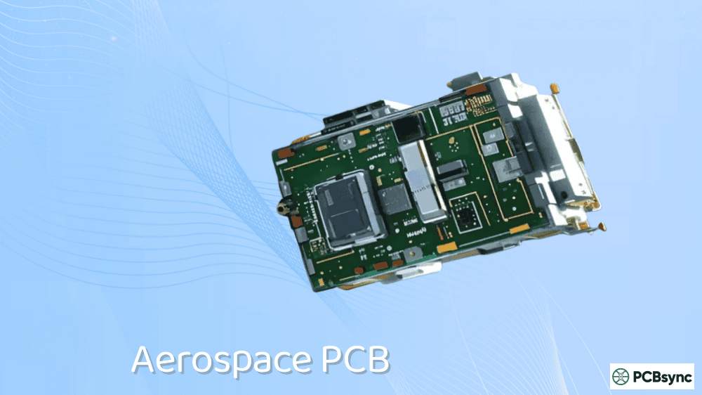
An aerospace PCB is a printed circuit board specifically engineered for aircraft, spacecraft, satellites, and defense systems. These boards represent the nervous system of modern aerospace technology—connecting and controlling everything from navigation systems to engine monitoring units.
What sets aerospace PCB apart from commercial-grade boards is the operating environment. Commercial electronics might face temperature variations of 20-30°C. Aerospace PCB assemblies routinely operate in environments ranging from -55°C to +125°C, with some space applications pushing beyond -170°C to +200°C. Add in extreme vibration during launch (up to 20G acceleration), cosmic radiation at high altitudes, and vacuum conditions in space, and you begin to understand why aerospace PCB manufacturing demands such stringent standards.
The aerospace and defense sector accounts for approximately 27% of the total PCB market, and this share continues to grow as systems become more electronically sophisticated. From the Full Authority Digital Engine Control (FADEC) systems managing jet engines to the Central Air Data Computers (CADC) processing flight information, aerospace PCB reliability directly impacts mission success and human safety.
Why Aerospace PCB Requirements Are Different
I’ve had engineers from other industries ask me why we can’t just use higher-quality commercial boards for aerospace applications. The answer lies in understanding the unique challenges these environments present.
Extreme Temperature Cycling
Aerospace PCB must withstand up to 2,000 thermal cycles from -40°C to 145°C—compared to just 300 cycles for standard boards. Space-bound boards face even more severe requirements, including thermal shock testing at 288°C for 10 seconds, repeated three times. This thermal cycling creates enormous stress on solder joints, vias, and layer interfaces, which is why material selection becomes so critical.
Vibration and Mechanical Stress
During rocket launch, PCBs experience vibration acceleration exceeding 20G—equivalent to a sustained strong earthquake. Aircraft components face continuous vibration throughout flight operations. Poor design choices that might go unnoticed in consumer electronics will cause immediate failure in aerospace applications. This is why through-hole technology still plays a role in certain aerospace PCB designs—those mechanical connections provide superior resistance to vibration-induced failures.
Radiation Exposure
High-energy cosmic rays can trigger Single Event Upset (SEU), causing stored data errors or even permanent component damage. For space applications, radiation-hardened components meeting MIL-PRF-38535 standards are mandatory. The aerospace PCB layout must also incorporate EMI shielding to protect against both external radiation and internally generated electromagnetic interference.
Long Operational Lifespan Requirements
Commercial products might have 3-5 year design lifespans. Aerospace PCB assemblies are expected to operate reliably for 10-15 years or longer, often in locations where maintenance access is limited or impossible. A satellite’s PCB can’t be repaired once it’s in orbit—it must work perfectly from day one through end of mission.
Essential Aerospace PCB Standards and Certifications
Understanding the standards framework is fundamental to aerospace PCB development. Here’s what you need to know about the key certifications and their requirements.
AS9100D Certification
AS9100D represents the cornerstone quality management standard for aerospace suppliers. Developed by the International Aerospace Quality Group (IAQG), it builds upon ISO9001 but adds aerospace-specific requirements including enhanced traceability, risk management protocols, and configuration control. Every aerospace PCB manufacturer worth considering holds this certification.
Key AS9100D requirements affecting aerospace PCB production include full traceability of materials and processes, mandatory First Article Inspection (FAI) per AS9102, and strict documentation control. If production lapses for more than 2 years or any design change occurs, a new FAI report is required.
IPC Standards for Aerospace PCB
IPC standards form the technical backbone of aerospace PCB manufacturing. All aerospace PCB assemblies must meet IPC-A-610 Class 3 or Class 3A acceptance criteria—the highest reliability standards in the industry. Class 3A represents space and military avionics addendum requirements that go beyond standard Class 3.
Key IPC Standards for Aerospace PCB:
Standard
Application
IPC-A-610 Class 3/3A
Acceptability standards for electronic assemblies; Class 3A is the highest reliability tier
IPC-6012DS
Space and military avionics addendum for rigid PCB qualification
IPC-6012ES
Performance and certification requirements for aerospace rigid PCBs
IPC-6013
Qualification and performance specification for flexible and rigid-flex PCBs
IPC-2221
Generic standard for PCB design covering layout, materials, and electrical properties
IPC-J-STD-001
Requirements for soldered electrical and electronic assemblies (includes Space Addendum)
Military Specifications (MIL-PRF Standards)
For defense applications, MIL-PRF standards define performance requirements. These aren’t optional—they’re mandatory compliance standards that aerospace PCB manufacturers must meet.
Critical MIL-PRF Standards:
MIL Standard
Scope
MIL-PRF-31032
Performance specification for multilayer printed wiring boards
MIL-PRF-55110
Qualification requirements for rigid single/double-sided and multilayer PCBs
MIL-PRF-50884
Performance specification for flexible and rigid-flex printed wiring boards
MIL-PRF-38535
Radiation-hardened component standards for space applications
MIL-STD-461
EMI/EMC requirements ensuring no electromagnetic interference
FAA and EASA Requirements
Civil aviation PCBs fall under FAA (Federal Aviation Administration) in the US and EASA (European Union Aviation Safety Agency) in Europe. Both agencies require environmental testing for temperature extremes, humidity, vibration, and EMI. The FAA uses FAR Part 21 for certification, while EASA follows Part 21, Subpart G with Production Organisation Approval (POA) requirements. Only certified factories can deliver to EASA programs.
Aerospace PCB Material Selection Guide
Material selection is where many aerospace PCB projects succeed or fail. Standard FR-4, while fine for commercial applications, simply cannot handle the thermal and mechanical demands of aerospace environments. Here’s what actually works in the field.
High-Tg FR-4 Laminates
Standard FR-4 has a glass transition temperature (Tg) around 130-140°C. High-Tg FR-4 pushes this to 170-180°C, providing better thermal stability for applications that don’t reach extreme temperatures. It’s more cost-effective than polyimide and works well for avionics systems in climate-controlled environments. However, for anything exposed to engine heat or space conditions, you’ll need something more robust.
Polyimide PCB Materials
Polyimide is the workhorse material for aerospace PCB applications requiring extreme temperature performance. With Tg values exceeding 250°C and operational temperature ranges from -200°C to +300°C, polyimide handles thermal conditions that would destroy other materials. DuPont’s Kapton polyimide films have been used in aerospace applications for decades, proving reliable in everything from satellite wiring to flexible circuits in high-temperature engine instrumentation.
Key polyimide properties for aerospace PCB applications include low coefficient of thermal expansion (CTE) around 12-14 ppm/°C, excellent dimensional stability through thermal cycling, low moisture absorption, and outstanding chemical resistance. The trade-off is cost—polyimide materials typically run 3-5 times more expensive than FR-4.
Ceramic and PTFE Substrates
For RF/microwave aerospace applications—radar systems, satellite communications, GPS—ceramic-filled laminates and PTFE (Teflon-based) materials become necessary. These offer extremely low dielectric loss, excellent thermal conductivity, and CTE values as low as 6-8 ppm/°C that closely match copper. Rogers Corporation materials like RO3003 and RT/duroid are industry standards for high-frequency aerospace PCB designs.
Good aerospace PCB design goes beyond just meeting specifications—it requires understanding how design choices affect long-term reliability in harsh environments. Here are the practical guidelines I’ve found most critical.
Aerospace PCB designs typically range from 2 to 42 layers, with most avionics applications falling in the 8-16 layer range. The minimum dielectric thickness between planes should be 3.5 mil to ensure mechanical strength and electrical isolation. Symmetrical stack-ups with uniform copper distribution prevent warping and twisting that could cause field failures.
For high-reliability applications, specify thickened hole copper at 35μm minimum (compared to 20μm for standard boards) using pulse plating technology. This ensures dense, uniform copper layers that resist micro-cracking through thermal cycling.
Thermal Management Design
Effective thermal management is non-negotiable in aerospace PCB design. Use thermal vias (typically 0.3mm drill, 1.0mm pitch) arranged in arrays under high-power components to conduct heat away from hotspots. For extreme thermal loads, heavy copper designs up to 20 oz provide the current carrying capacity and heat spreading needed for power electronics.
Metal-core PCBs using aluminum or copper substrates offer superior heat dissipation for applications like LED lighting systems and power converters. The metal core can also serve as a large ground plane, improving EMI performance in high-speed designs.
Signal Integrity Considerations
Aerospace systems increasingly handle high-speed data—10 Gbps and beyond for satellite communication links. Poor signal integrity leads to data loss and potential system failure. Use controlled impedance traces with tight tolerances, minimize via stubs, and route differential pairs with matched lengths (within 5 mils). Maintain ground plane clearance of at least 0.25mm from signal traces to reduce noise.
For high-voltage circuits common in power distribution systems, set clearance distances based on peak operating voltage and altitude conditions. IPC-2221 provides the reference standards for high-voltage clearance calculations. Insufficient clearance can cause arcing, particularly at high altitudes where air pressure is lower.
Redundancy and Fail-Safe Design
Single points of failure are unacceptable in aerospace PCB design. For critical systems like navigation and flight control, duplicate key components and circuits. Redundant vias on every layer guarantee electrical connection even if individual vias fail. Component placement should be strategic—keep critical components away from board edges where mechanical stress concentrates during vibration.
Aerospace PCB Manufacturing and Assembly
Manufacturing aerospace PCB assemblies requires capabilities and controls far beyond standard PCB production. Here’s what distinguishes aerospace-grade manufacturing.
Cleanroom Assembly Requirements
All aerospace PCB assembly must occur in Class 10,000 cleanroom and anti-static environments. Contamination that might be acceptable in commercial products can cause catastrophic failures in aerospace applications. This includes particulate contamination affecting solder joints and ionic contamination causing long-term corrosion.
Surface Mount Technology (SMT) Process
The aerospace PCB assembly process follows a rigorous sequence: solder paste printing → 3D SPI (solder paste inspection) → component placement → X-ray inspection → reflow soldering → 3D AOI (automated optical inspection) → value-added processing and testing. Each step includes verification checkpoints that would be considered excessive in commercial production but are essential for aerospace reliability.
Nitrogen reflow soldering replaces standard reflow for aerospace assemblies. Nitrogen’s inert properties prevent solder joint oxidation and reduce flux volatilization, resulting in higher-quality joints with improved long-term reliability.
Conformal Coating Application
Conformal coatings protect finished aerospace PCB assemblies from moisture, chemicals, radiation, and thermal stress. Coating selection depends on operating conditions:
Acrylic coatings: Service temperature -65°C to +125°C, good moisture resistance, easy to repair
Silicone coatings: Extended temperature range to +200°C, excellent flexibility for absorbing vibration
Parylene-C: Uniform coverage down to 1μm thickness, superior barrier properties, ideal for space applications
All coatings must comply with MIL-I-46058C requirements. Application occurs in humidity-controlled laminar flow booths with selective masking for connectors and test points.
Surface Finish Options
Preferred surface finishes for aerospace PCB include ENIG (Electroless Nickel Immersion Gold), hard gold for connector fingers and high-wear areas, and HASL for less demanding applications. ENIG offers the best combination of reliability, solderability, and corrosion resistance for most aerospace applications. Its inert surface minimizes outgassing concerns critical for space environments.
Aerospace PCB Testing and Quality Assurance
Testing represents where aerospace PCB production diverges most dramatically from commercial manufacturing. Every board undergoes testing that would be economically impossible in consumer electronics.
Environmental Stress Screening (ESS)
Environmental Stress Screening subjects aerospace PCB assemblies to accelerated aging conditions to identify early failures before deployment. This includes temperature cycling from -55°C to +125°C, vibration testing simulating launch and operational conditions, and combined environmental stresses. Boards that survive ESS have demonstrated robustness beyond what theoretical analysis can predict.
Thermal Shock Testing
Aerospace PCB undergoes thermal shock testing at 288°C for 10 seconds, repeated three times. This simulates the thermal gradients experienced during reflow soldering and identifies boards with marginal solder joints or material defects. Space-grade boards undergo even more severe protocols—up to 1,000 thermal cycles from -55°C to +125°C to simulate years of space temperature alternation.
Electrical Testing
In-Circuit Testing (ICT) checks for manufacturing defects including open circuits, shorts, and incorrect component values. For aerospace PCB, ICT must cover 100% of nets—no sampling allowed. Functional testing follows, simulating real-world operating conditions to verify the complete assembly performs as designed. AS9100 requires detailed documentation of all test results.
Inspection Methods
Aerospace PCB inspection combines multiple methods to catch defects that any single technique might miss:
3D SPI (Solder Paste Inspection): Verifies accurate solder paste application before component placement
3D X-ray: Examines hidden connections, BGA solder balls, and internal via structures
3D AOI: Inspects surface defects including misaligned components, cold solder joints, and bridging
Cross-sectional analysis: Destructive testing on sample boards to verify internal layer quality
Burn-in testing: Extended operational testing under stress conditions to identify infant mortality failures
Aerospace PCB Applications
Aerospace PCB technology enables critical systems across the aviation and space industries. Understanding these applications helps inform design priorities and material selection.
Avionics Systems
Flight control computers, navigation units, and cockpit displays rely on high-density interconnect (HDI) aerospace PCB designs that pack maximum functionality into minimum space and weight. Weight reduction directly affects fuel efficiency—every gram saved in PCB weight contributes to operational cost savings over the aircraft’s lifetime. Typical avionics applications use rigid-flex constructions for compact packaging and vibration resistance.
Satellite and Space Systems
Communication transceivers, data acquisition units, and payload controllers for satellites demand the highest-reliability aerospace PCB assemblies available. These boards must survive launch vibration, operate in vacuum conditions without outgassing, resist radiation damage, and function through extreme thermal cycling between sun exposure and shadow. Polyimide substrates with radiation-hardened components are standard for space applications.
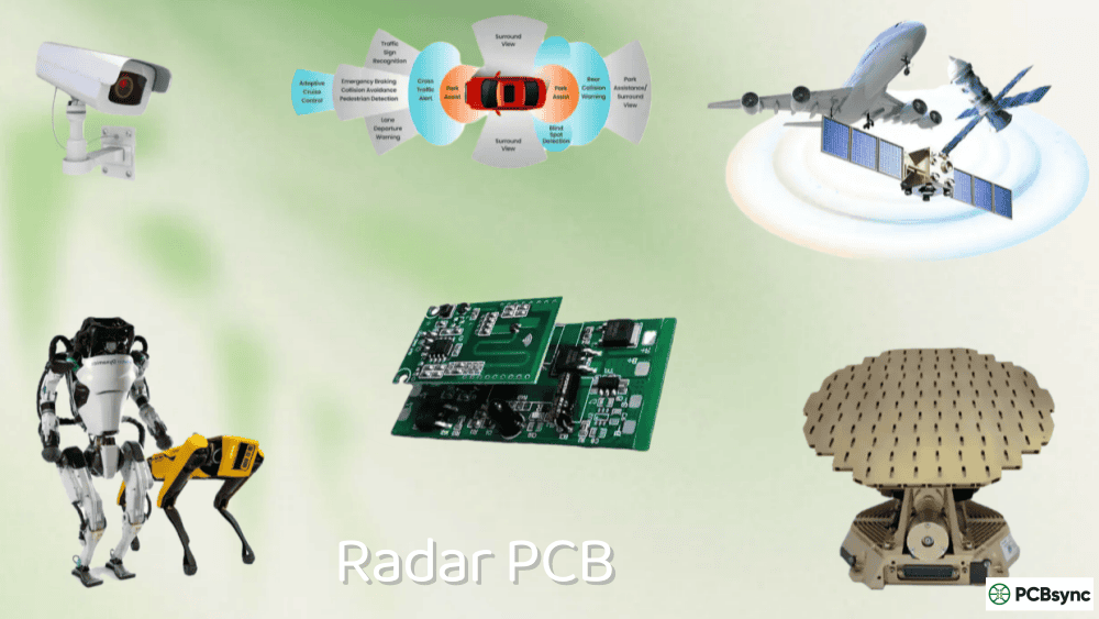
Radar and Communication Systems
Ground-based and airborne radar systems, satellite communications, and high-frequency data links require RF/microwave aerospace PCB using PTFE or ceramic-filled laminates. Signal integrity at frequencies exceeding several GHz demands precise impedance control and low-loss materials that maintain performance across the operating temperature range.
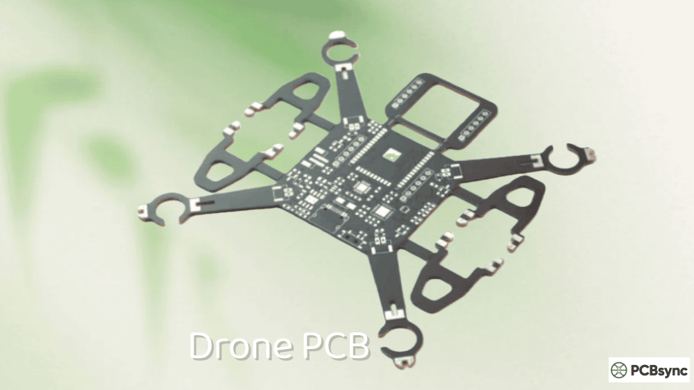
UAV and Drone Systems
Unmanned aerial vehicles require aerospace PCB that combines lightweight design with military-grade reliability. Flight control modules, navigation systems, and payload electronics must operate continuously in varying conditions while minimizing weight impact on flight endurance. Flexible and rigid-flex PCB constructions are common for fitting into compact UAV airframes.
Engine Control and Power Systems
Full Authority Digital Engine Control (FADEC) systems and power distribution units operate in some of the harshest thermal environments in aerospace. Heavy copper aerospace PCB designs up to 20 oz handle high current loads while dissipating significant heat. Polyimide substrates are mandatory for boards exposed to engine compartment temperatures.
Useful Resources for Aerospace PCB Development
Access to authoritative reference materials accelerates aerospace PCB development and helps ensure compliance. Here are the most valuable resources I recommend.
Standards Organizations
IPC Standards: www.ipc.org – Complete library of PCB design, manufacturing, and acceptance standards
SAE International: www.sae.org – AS9100 and other aerospace standards documentation
IAQG (International Aerospace Quality Group): www.iaqg.org – Aerospace quality standards development
Defense Logistics Agency: quicksearch.dla.mil – MIL-PRF specifications and military standards database
NASA Technical Reports Server: ntrs.nasa.gov – Space-grade electronics research and standards
Frequently Asked Questions About Aerospace PCB
1. What makes aerospace PCB different from commercial PCB?
Aerospace PCB differs from commercial boards in material selection, design standards, manufacturing processes, and testing requirements. Aerospace boards use high-temperature materials like polyimide (Tg 250°C+) instead of standard FR-4, must meet IPC Class 3/3A acceptance criteria with zero-defect tolerance, undergo environmental stress screening including thermal shock and vibration testing, and require full traceability of all materials and processes. Commercial boards might have 3-5% acceptable defect rates; aerospace boards require 100% reliability.
2. What certifications should an aerospace PCB manufacturer have?
At minimum, aerospace PCB manufacturers should hold AS9100D certification for quality management. For defense work, ITAR (International Traffic in Arms Regulations) registration is mandatory. Additional valuable certifications include Nadcap accreditation for critical processes, ISO 9001 as a foundation, and specific IPC certifications (IPC-A-610 CIS, IPC-A-620 CIS) for trained inspectors. Verify certifications before engaging any manufacturer—ask for current certificates and audit history.
3. Which PCB materials are best suited for space applications?
Space applications require polyimide substrates for their exceptional thermal stability (-200°C to +300°C operational range), low outgassing properties (critical in vacuum), and radiation resistance. For RF/microwave space systems, PTFE and ceramic-filled laminates maintain signal integrity. Standard FR-4 is never acceptable for space—it lacks the thermal and radiation resistance required. Material selection should also consider CTE matching with components to prevent solder joint failures through thermal cycling.
4. How long does aerospace PCB manufacturing typically take?
Aerospace PCB manufacturing takes significantly longer than commercial production due to rigorous quality controls. Standard 4-8 layer aerospace boards typically require 2-4 weeks. Complex multilayer designs (10+ layers) with HDI features may take 4-8 weeks. First article inspection adds time for initial production runs. Quick-turn prototypes for design validation are available from some manufacturers in 5-10 days, but full aerospace-qualified production always requires extended schedules to complete all required testing and documentation.
5. What testing is mandatory for aerospace PCB assemblies?
Mandatory testing for aerospace PCB includes 100% electrical testing (ICT and flying probe), automated optical inspection (AOI), X-ray inspection for hidden joints and BGAs, and functional testing under simulated operating conditions. Environmental testing requirements depend on the application but typically include thermal cycling, thermal shock at 288°C, vibration testing, and burn-in. Space-grade boards require additional radiation testing and outgassing measurements. All test results must be documented for AS9100 compliance and customer traceability requirements.
Conclusion
Aerospace PCB development demands a fundamentally different approach than commercial electronics. The combination of extreme environments, zero-tolerance reliability requirements, and long operational lifespans creates challenges that can only be met through rigorous attention to standards, materials, design, and manufacturing processes.
Whether you’re working on your first aerospace PCB project or optimizing an existing design, remember that compliance with AS9100, IPC Class 3/3A, and relevant MIL-PRF standards isn’t just bureaucratic overhead—these standards encode decades of hard-won knowledge about what works in aerospace applications and what doesn’t.
Start with material selection appropriate for your operating environment, design with redundancy and thermal management as priorities, partner with certified manufacturers who understand aerospace requirements, and never skip testing steps. The investment in doing aerospace PCB development correctly pays dividends in reliability that protects both mission success and human safety.
Inquire: Call 0086-755-23203480, or reach out via the form below/your sales contact to discuss our design, manufacturing, and assembly capabilities.
Quote: Email your PCB files to Sales@pcbsync.com (Preferred for large files) or submit online. We will contact you promptly. Please ensure your email is correct.
Notes: For PCB fabrication, we require PCB design file in Gerber RS-274X format (most preferred), *.PCB/DDB (Protel, inform your program version) format or *.BRD (Eagle) format. For PCB assembly, we require PCB design file in above mentioned format, drilling file and BOM. Click to download BOM template To avoid file missing, please include all files into one folder and compress it into .zip or .rar format.


