Inquire: Call 0086-755-23203480, or reach out via the form below/your sales contact to discuss our design, manufacturing, and assembly capabilities.
Quote: Email your PCB files to Sales@pcbsync.com (Preferred for large files) or submit online. We will contact you promptly. Please ensure your email is correct.
Notes: For PCB fabrication, we require PCB design file in Gerber RS-274X format (most preferred), *.PCB/DDB (Protel, inform your program version) format or *.BRD (Eagle) format. For PCB assembly, we require PCB design file in above mentioned format, drilling file and BOM. Click to download BOM template To avoid file missing, please include all files into one folder and compress it into .zip or .rar format.
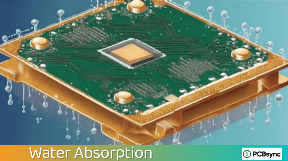
After 15 years of working with printed circuit boards across everything from consumer electronics to aerospace applications, I’ve learned that water absorption is one of those silent killers that can ruin an otherwise perfectly designed PCB. It’s not as glamorous as high-speed signal integrity or thermal management, but understanding how moisture interacts with your board materials can mean the difference between a product that lasts decades and one that fails within months.
Let me walk you through everything I’ve learned about water absorption in PCB materials, from the basic science to practical mitigation strategies.
Water absorption refers to the ability of PCB laminate materials to take up and retain moisture from their surrounding environment. Every PCB substrate, whether it’s the ubiquitous FR-4 or exotic PTFE-based materials, has some capacity to absorb water molecules. This characteristic is typically expressed as a percentage of weight gain after immersing the material in water for 24 hours under controlled conditions.
The resin systems used in PCBs are inherently hygroscopic, which means they naturally attract and hold water molecules from humid air or direct liquid contact. This isn’t a manufacturing defect; it’s simply the physics of how polymeric materials behave. The glass fiber reinforcement in most laminates doesn’t absorb significant moisture, but the epoxy resin matrix surrounding those fibers certainly does.
When we talk about water absorption values, we’re typically referencing tests performed according to IPC-TM-650 Method 2.6.2.1A, where samples are immersed in distilled water at 23°C for 24 hours. The resulting weight change tells us how much moisture the material can absorb under standardized conditions.
Why Water Absorption Matters for Your PCB Design
You might wonder why a fraction of a percent weight change matters. Here’s where practical experience comes in. I’ve seen production batches fail during reflow soldering because moisture trapped in the laminate vaporized explosively at lead-free temperatures (around 260°C). The steam pressure generated can reach 575 psi at these temperatures, enough force to blow apart via barrels or cause catastrophic delamination between copper layers.
Beyond assembly issues, absorbed moisture affects your board’s electrical performance in several critical ways:
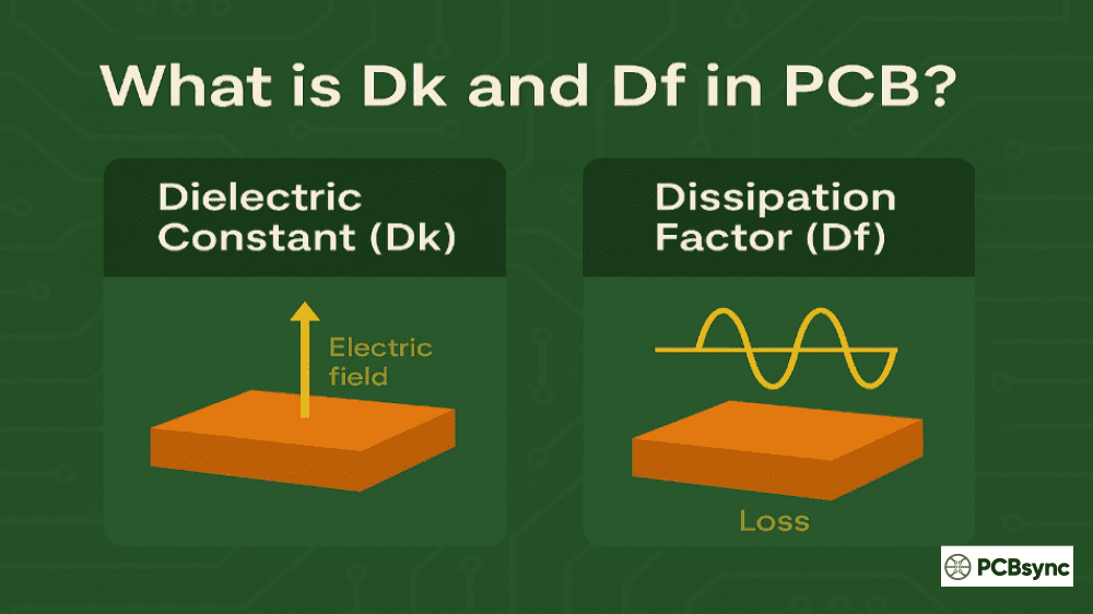
Dielectric Constant Shifts: Water has a dielectric constant around 80, compared to approximately 4.2 for standard FR-4. Even small amounts of absorbed moisture can shift your laminate’s effective Dk value, throwing off carefully calculated impedance values on high-speed signal traces.
Increased Dissipation Factor: Moisture increases signal losses, particularly at higher frequencies. If you’re designing RF circuits or high-speed digital interfaces, moisture-induced losses can degrade signal integrity significantly.
Reduced Insulation Resistance: The presence of water molecules creates paths for leakage current, potentially causing crosstalk between traces or even outright short circuits in severe cases.
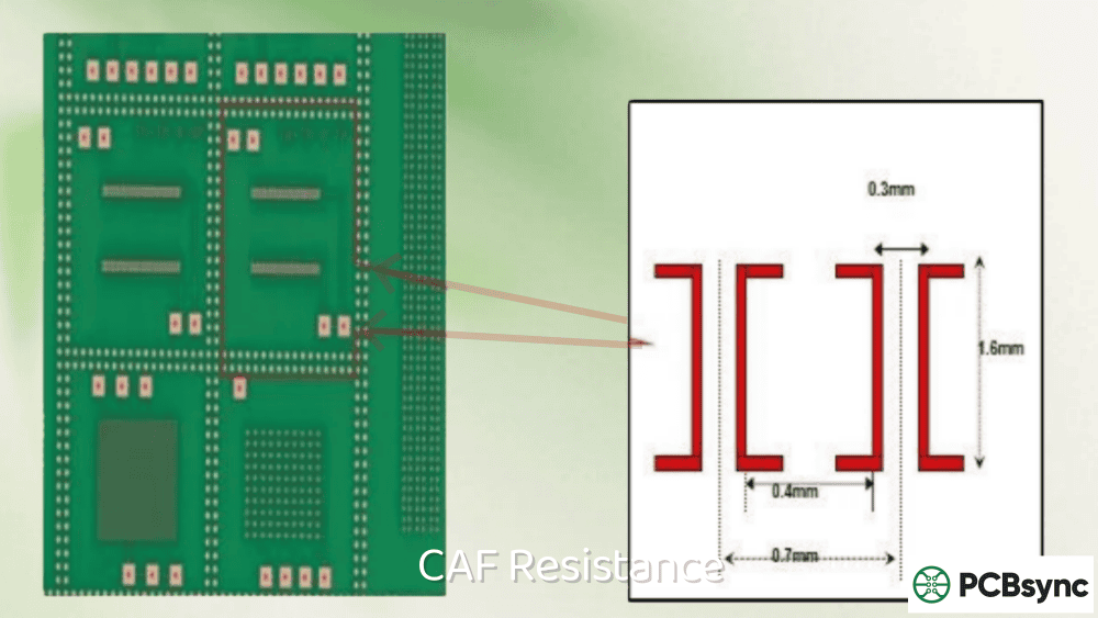
Conductive Anodic Filament (CAF) Formation: Perhaps the most insidious failure mode, CAF occurs when moisture enables electrochemical migration along the glass fiber-resin interfaces. Over time, conductive copper filaments grow through the laminate, eventually creating short circuits between adjacent conductors.
How Moisture Enters PCB Materials
Understanding the pathways for moisture ingress helps us design better protection strategies. There are two primary mechanisms at work:
Bulk Diffusion
This is the primary route for moisture absorption. Water molecules penetrate through the resin matrix following Fick’s Law of Diffusion, moving from regions of high concentration (the surrounding air or liquid) to lower concentration (inside the laminate). The rate depends on temperature, humidity level, and the specific resin formulation. Higher temperatures accelerate diffusion rates considerably.
Surface Adsorption
Moisture can also cling to exposed PCB surfaces, particularly on areas where the solder mask has been removed or incompletely cured. This surface moisture doesn’t necessarily penetrate deep into the laminate, but it can cause problems during thermal excursions and may eventually diffuse into the bulk material.
Water Absorption Rates of Common PCB Materials
Not all PCB materials absorb moisture equally. The table below compares water absorption characteristics of commonly used substrates:
Several important observations emerge from this data:
PTFE-based materials exhibit the lowest water absorption rates, making them ideal choices for applications in humid environments or where long-term reliability is paramount. The nearly zero water absorption of pure PTFE materials is one reason they dominate in aerospace and military applications despite their higher cost and manufacturing challenges.
Interestingly, polyimide materials used in flexible circuits show higher moisture absorption than rigid FR-4, which might seem counterintuitive given their reputation for durability. However, polyimide’s other properties, including excellent thermal stability and flexibility, often outweigh this drawback in appropriate applications.
Standard FR-4 with lower glass transition temperatures tends to absorb more moisture than high-Tg variants. This is one often-overlooked reason to specify high-Tg materials for boards that will see humid environments, even if the application doesn’t demand the thermal performance.
Effects of Moisture on PCB Reliability
Delamination During Soldering
When a moisture-laden PCB enters a reflow oven, the absorbed water rapidly vaporizes. At lead-free soldering temperatures (typically 245-260°C peak), the steam pressure generated can force layers apart. I’ve seen boards come out of reflow with visible blisters and blown-out via barrels. The vapor preferentially escapes through the weakest structural points, which are often plated through-holes or the copper-to-laminate interface.
The IPC guidelines recommend keeping moisture content below 0.1% by weight for high-temperature (260°C) soldering and below 0.2% for standard (230°C) processes. Exceeding these limits dramatically increases the risk of assembly failures.
Dimensional Instability
PCB materials expand when they absorb moisture. This expansion may seem trivial, but on fine-pitch BGA assemblies or high-density interconnects, even small dimensional changes can stress solder joints or cause registration issues between layers. Over time, cyclic absorption and desorption can fatigue solder connections.
Electrical Performance Degradation
Beyond the signal integrity issues mentioned earlier, moisture absorption can reduce the effective operating frequency range of high-frequency circuits. The increased dielectric losses at microwave frequencies can render otherwise functional RF designs unusable in humid conditions.
Long-Term Reliability Issues
CAF formation remains one of the most concerning moisture-related failure modes for long-life products. The electrochemical process that creates conductive filaments requires moisture, ionic contamination, and an electric field. In applications expected to operate for 10+ years, CAF resistance testing should be part of your qualification process.
IPC Standards for Water Absorption Testing
The electronics industry relies on standardized test methods to characterize material properties consistently. For water absorption, several IPC methods apply:
IPC-TM-650 Method 2.6.2.1A: The primary test method for measuring water absorption in metal-clad laminates. Samples are conditioned, weighed, immersed in distilled water at 23°C for 24 hours, and reweighed. Results are expressed as percentage weight gain.
IPC-TM-650 Method 2.6.2: Covers moisture absorption testing for flexible printed wiring materials, with slightly different procedures suited to flexible substrates.
IPC-TM-650 Method 2.6.28: Gravimetric method for determining moisture content in assembled PCBs, useful for verifying bake-out effectiveness.
IPC-4101: The specification for base materials includes moisture absorption requirements organized by material “slash sheets” (e.g., /24, /26, /99, /124) that define acceptable performance levels for different laminate grades.
IPC-1601: Provides comprehensive guidelines for handling and storage of PCBs to minimize moisture absorption before assembly, including recommended baking procedures.
Practical Strategies to Mitigate Water Absorption Issues
Material Selection
Choosing the right laminate for your application environment is the first line of defense. If your product will operate in humid conditions or outdoor environments, investing in lower-absorption materials pays dividends in reliability. High-Tg FR-4 offers improved moisture resistance over standard grades at modest cost increases.
For critical applications, consider PTFE-based materials or ceramic-filled composites. While more expensive and challenging to manufacture, their near-zero moisture absorption eliminates many reliability concerns.
Design Considerations
Your PCB layout can influence moisture-related reliability. Avoid designs with large uninterrupted copper planes on external layers when possible, as these can trap moisture during baking and actually increase localized moisture concentration before it eventually dissipates. Including an appropriate density of plated through-holes can improve moisture desorption rates during baking.
Consider the placement of high-reliability components relative to board edges and via patterns. Moisture diffuses from exposed edges inward, so critical circuits positioned near board centers may experience different moisture exposure than those near edges.
Manufacturing and Storage Controls
Work with your fabricator to ensure proper moisture control throughout manufacturing. PCBs should be stored in humidity-controlled environments (typically below 30% RH) and packaged in moisture barrier bags with desiccant packs and humidity indicator cards for shipment.
Implement floor-life tracking for unpacked PCBs. Once removed from protective packaging, boards begin absorbing moisture immediately. IPC guidelines recommend limiting exposure time before assembly based on board thickness and ambient conditions.
Pre-Assembly Baking
Baking PCBs before assembly remains the most effective method for removing absorbed moisture. Standard bake profiles range from 105°C to 125°C for durations of 2 to 24 hours, depending on board thickness, construction, and measured moisture content.
Board Thickness
Bake Temperature
Typical Duration
< 0.8 mm
105-115°C
2-4 hours
0.8 – 1.6 mm
115-125°C
4-8 hours
1.6 – 2.4 mm
120-125°C
8-16 hours
> 2.4 mm
120-125°C
16-24 hours
Important caveats apply. Excessive baking temperatures or durations can damage solder masks, oxidize surface finishes, or degrade the laminate itself. Never bake above the glass transition temperature of your material. Some surface finishes like OSP (Organic Solderability Preservative) are particularly sensitive to extended thermal exposure.
Conformal Coating and Encapsulation
For assembled boards operating in harsh environments, conformal coatings provide an additional moisture barrier. Options include acrylic, urethane, silicone, and parylene coatings, each with different performance characteristics:
Coating Type
Moisture Barrier
Temperature Range
Key Benefits
Acrylic
Good
-65°C to +125°C
Easy application, reworkable
Urethane
Excellent
-65°C to +125°C
Chemical resistance
Silicone
Good
-65°C to +200°C
High-temperature performance
Parylene
Excellent
-65°C to +150°C
Ultra-thin, uniform coverage
Epoxy
Excellent
-65°C to +150°C
Rigid, high protection
Parylene coatings, applied via vapor deposition, provide exceptional moisture protection in extremely thin layers (typically 0.5-25 μm). They’re commonly used in medical devices, aerospace electronics, and other high-reliability applications.
Useful Resources and Database Links
For engineers seeking deeper technical information, the following resources are invaluable:
IPC Standards Portal (ipc.org): Access to IPC-TM-650 test methods, IPC-4101 laminate specifications, and IPC-1601 handling guidelines.
Isola Group Technical Library (isola-group.com): Detailed datasheets and application notes for FR-4 and high-performance laminates, including moisture absorption data.
Rogers Corporation Design Support (rogerscorp.com): Comprehensive material data for PTFE and ceramic-filled laminates, including design calculators.
CALCE (Center for Advanced Life Cycle Engineering) at University of Maryland (calce.umd.edu): Academic research on PCB reliability, including moisture-related failure mechanisms.
IPC EDGE Online Learning (ipc.org/ipc-edge): Training courses on PCB materials and reliability.
electronics.org Test Methods: Free access to IPC-TM-650 test method documents.
Frequently Asked Questions About Water Absorption in PCBs
What is the acceptable water absorption percentage for FR-4 PCB material?
Standard FR-4 materials typically show water absorption of 0.10% to 0.20% when tested per IPC-TM-650 Method 2.6.2.1A (24-hour immersion at 23°C). High-Tg FR-4 variants often achieve lower values around 0.10%. For most general-purpose applications, values at or below 0.15% are considered acceptable. However, specific requirements depend on your application’s environmental conditions and reliability targets.
How long should I bake PCBs to remove moisture before soldering?
Baking duration depends primarily on board thickness and construction. Thin boards under 0.8mm typically require 2-4 hours at 105-115°C, while thick multilayer boards over 2.4mm may need 16-24 hours at 120-125°C. The key is achieving moisture content below 0.1% for lead-free assembly or below 0.2% for standard processes. Monitoring actual moisture content through gravimetric measurement provides more reliable results than time-based baking alone.
Can absorbed moisture cause PCB failure during reflow soldering?
Absolutely. Moisture absorbed by PCB laminates vaporizes rapidly during reflow, generating internal steam pressure that can exceed 575 psi at lead-free temperatures (260°C). This pressure can cause delamination between copper and dielectric layers, blow out plated through-hole barrels, or create measles (white spots) in the laminate. These defects may not be immediately visible but compromise long-term reliability. Proper pre-baking before assembly is essential for preventing moisture-induced reflow failures.
Which PCB material has the lowest water absorption for humid environments?
PTFE (Teflon) based materials offer the lowest water absorption rates, typically below 0.02%, with some formulations approaching zero. Ceramic substrates like alumina also exhibit virtually no moisture absorption. For applications requiring excellent moisture resistance without the cost and manufacturing complexity of PTFE, ceramic-filled hydrocarbon laminates like Rogers RO4350B offer a good compromise with absorption rates around 0.06%.
How does moisture affect PCB impedance and signal integrity?
Water has a dielectric constant of approximately 80, dramatically higher than typical PCB materials (4-5 for FR-4). When moisture absorbs into the laminate, it effectively increases the material’s dielectric constant, which lowers trace impedance. Additionally, moisture increases the dissipation factor, causing greater signal attenuation at high frequencies. For controlled-impedance designs, moisture absorption can shift impedance values outside acceptable tolerances and degrade high-speed signal quality.
Conclusion: Building Moisture-Resistant PCBs
Water absorption in PCB materials isn’t something you can eliminate entirely, but understanding how moisture interacts with different substrates empowers you to make informed design decisions. Start by selecting appropriate materials for your operating environment, implement proper handling and storage procedures throughout manufacturing, and apply conformal coatings where conditions warrant.
The most reliable approach combines multiple strategies: choosing lower-absorption materials where practical, designing boards that can be effectively baked before assembly, implementing rigorous moisture control in manufacturing, and protecting finished assemblies with appropriate coatings or encapsulation.
Remember that moisture-related failures often don’t appear immediately. They develop over months or years of service, making them particularly costly to diagnose and address. Investing effort upfront in understanding and mitigating water absorption issues pays substantial dividends in field reliability and customer satisfaction.
Inquire: Call 0086-755-23203480, or reach out via the form below/your sales contact to discuss our design, manufacturing, and assembly capabilities.
Quote: Email your PCB files to Sales@pcbsync.com (Preferred for large files) or submit online. We will contact you promptly. Please ensure your email is correct.
Notes: For PCB fabrication, we require PCB design file in Gerber RS-274X format (most preferred), *.PCB/DDB (Protel, inform your program version) format or *.BRD (Eagle) format. For PCB assembly, we require PCB design file in above mentioned format, drilling file and BOM. Click to download BOM template To avoid file missing, please include all files into one folder and compress it into .zip or .rar format.


