Inquire: Call 0086-755-23203480, or reach out via the form below/your sales contact to discuss our design, manufacturing, and assembly capabilities.
Quote: Email your PCB files to Sales@pcbsync.com (Preferred for large files) or submit online. We will contact you promptly. Please ensure your email is correct.
Notes: For PCB fabrication, we require PCB design file in Gerber RS-274X format (most preferred), *.PCB/DDB (Protel, inform your program version) format or *.BRD (Eagle) format. For PCB assembly, we require PCB design file in above mentioned format, drilling file and BOM. Click to download BOM template To avoid file missing, please include all files into one folder and compress it into .zip or .rar format.
When I first started working on defense contracts back in 2012, I quickly learned that designing a military PCB isn’t just about following a checklist—it’s about understanding why every specification exists. A single failure in an aerospace PCB powering a satellite communication system or a military radar unit can mean mission failure, lost equipment worth millions, or worse. That’s the reality we work with in this industry.
This guide covers everything you need to know about military and aerospace PCB design, from the fundamental MIL-SPEC standards to practical assembly considerations. Whether you’re transitioning from commercial electronics or looking to deepen your knowledge of defense-grade boards, you’ll find actionable information here.
Military PCBs and aerospace PCBs operate in environments that would destroy standard commercial boards within hours. We’re talking about temperature swings from -55°C to +125°C, constant vibration, exposure to radiation at high altitudes, and the need for decades of reliable operation without maintenance.
The fundamental difference comes down to three factors: reliability requirements, environmental extremes, and regulatory compliance. While a consumer electronics PCB might have an acceptable failure rate of 1 in 1,000 units, military applications often demand failure rates closer to 1 in 1,000,000. Aerospace PCB applications in satellites need to function for 15+ years without any possibility of repair.
Consider what happens inside a fighter jet during combat maneuvers—the electronics experience up to 9G forces while operating in an environment filled with electromagnetic interference from radar systems, communication equipment, and weapons systems. Every aerospace PCB in that aircraft must maintain perfect signal integrity under these conditions.
Key Differences Between Commercial and Military Grade PCBs
The alphabet soup of military specifications can be overwhelming at first, but each standard serves a specific purpose. Let me break down the ones you’ll encounter most frequently when designing military and aerospace PCBs.
MIL-PRF-31032: The Primary Performance Specification
MIL-PRF-31032 is the governing specification for military PCB manufacturing. It replaced the older MIL-PRF-55110 standard and establishes performance requirements for printed circuit boards while giving manufacturers flexibility to implement best commercial practices.
The specification operates through a Qualified Manufacturers List (QML) program managed by the Defense Logistics Agency (DLA). To get your aerospace PCB certified under this specification, your manufacturer must:
Establish an internal Technical Review Board (TRB)
Submit PCB samples for qualification testing every two years
Perform monthly sampling of demanding military PCBs to DLA-certified labs
Maintain ongoing compliance audits
The MIL-PRF-31032 family includes several slash sheets for specific board types:
Specification
Board Type
MIL-PRF-31032/1
Rigid multilayer, thermosetting resin
MIL-PRF-31032/2
Rigid single/double layer
MIL-PRF-31032/3
Flexible single/double layer
MIL-PRF-31032/4
Rigid-flex and flexible multilayer
MIL-PRF-31032/5
Rigid multilayer for high-frequency
MIL-PRF-31032/6
Single/double layer for high-frequency
MIL-PRF-55110: Legacy Standard Still in Use
While you can no longer qualify new products to MIL-PRF-55110, it remains in play for legacy military programs. Many defense systems designed decades ago still require boards manufactured to this specification. The military moves slowly when it comes to change, and there’s significant business supporting these legacy requirements.
MIL-PRF-50884: Flexible Circuit Requirements
For flexible PCBs used in aerospace applications, MIL-PRF-50884 sets the performance standards. Flex circuits are increasingly common in military systems where weight reduction and space constraints matter—think about wiring harnesses in aircraft or connections between moving parts in targeting systems.
Aerospace PCB Design Standards: IPC and AS9100
Beyond military specifications, aerospace PCB design must comply with industry standards that ensure quality and reliability across the global supply chain.
IPC Class 3 and Class 3A Requirements
IPC-A-610 defines three classes of electronic assemblies, with Class 3 representing high-performance products where continued operation is critical. Class 3A, found in the IPC-6012DS addendum, goes even further for space and military avionics applications.
For your aerospace PCB to meet Class 3A requirements, every aspect of design and manufacturing faces scrutiny:
Copper plating: Minimum 25 μm (0.001″) in plated through holes
Conductor width reduction: Maximum 20% from artwork
Surface defects: Zero tolerance for measling, crazing that affects function
AS9100D: Quality Management for Aerospace
AS9100D certification is the aerospace industry’s quality management standard, building on ISO 9001 with additional requirements specific to aviation, space, and defense. While AS9100 focuses on quality systems rather than product specifications, it’s essential for any manufacturer supplying aerospace PCBs.
The standard requires:
Product safety considerations throughout design and production
Critical Design Considerations for Military PCB Projects
After reviewing hundreds of aerospace PCB designs over my career, I’ve identified the factors that separate reliable military boards from those that fail qualification testing. The difference often lies in understanding that military PCB design isn’t just about meeting specifications—it’s about anticipating failure modes and designing them out before they occur.
Layer Stackup and Aspect Ratio Guidelines
Proper stackup design forms the foundation of any reliable aerospace PCB. For military applications, I recommend maintaining a maximum aspect ratio of 10:1 for plated through holes. This means a 100 mil (2.5mm) thick board should have minimum hole diameters of 10 mil (0.25mm).
The stackup should be symmetrical to prevent warpage during thermal excursions. Copper weight should be balanced across the board thickness—if you have 2 oz copper on layer 1, match it with 2 oz on the opposite external layer. Internal copper distribution should also be balanced to minimize stress during lamination and soldering.
For high-layer-count aerospace PCB designs (20+ layers), consider using sequential lamination with buried vias to maintain aspect ratios while achieving the required density. This approach, while more expensive, significantly improves reliability compared to pushing aspect ratios beyond 12:1.
Thermal Management Strategies
Heat is the enemy of reliability. In military applications, your aerospace PCB might need to dissipate significant power while operating in an environment where ambient temperatures already exceed 85°C. Here’s what works:
Heavy copper construction using 2-4 oz/ft² copper (or heavier for power applications) improves heat spreading and reduces thermal resistance. Many military power distribution boards use copper weights up to 20 oz/ft² in critical areas.
Thermal via arrays beneath high-power components provide direct paths to internal copper planes or external heatsinks. I typically specify 0.3mm diameter vias on 1.0mm pitch, filled and capped for reliability under thermal cycling.
Material selection matters enormously. Standard FR-4 has a glass transition temperature (Tg) around 130°C—far too low for military applications. Instead, specify materials like:
Military equipment experiences vibration levels that would shake apart commercial electronics. The MIL-STD-810G specification defines environmental testing requirements, and your aerospace PCB design must anticipate these stresses.
Component mounting requires careful attention. Through-hole components generally survive vibration better than surface mount, but SMT is often necessary for density. When using SMT, consider underfilling BGAs and adding corner staking for large packages.
Board geometry affects resonant frequency. Avoid aspect ratios greater than 3:1 where possible, and ensure mounting points are positioned to minimize board flexure. A symmetrical stackup with uniform copper distribution reduces warping that can concentrate stress.
Solder joint design for military applications often specifies larger pad sizes and fillet heights compared to commercial standards. The additional solder volume provides mechanical strength and better fatigue resistance.
Signal Integrity and EMI/EMC Compliance
Military systems operate in electromagnetically contested environments. Your aerospace PCB must not only function despite interference but also avoid creating interference that affects other systems. MIL-STD-461 defines the EMI/EMC requirements.
Design practices that help achieve compliance:
Implement solid ground planes immediately adjacent to signal layers
Keep high-speed traces away from board edges
Use guard traces around sensitive clock signals
Maintain controlled impedance for all high-speed signals (typically 50Ω single-ended, 100Ω differential)
Include EMI filtering at all cable interfaces
Redundancy and Fault Tolerance
Mission-critical aerospace PCB designs often incorporate redundancy strategies that would seem excessive in commercial applications. Triple modular redundancy (TMR) for critical circuits ensures continued operation even with component failures. Backup power paths with automatic failover prevent single points of failure in power distribution.
Beyond circuit redundancy, consider failure containment in your military PCB design. Faults in one section shouldn’t propagate to affect other functions. This means careful partitioning of power rails, isolation between functional blocks, and sometimes physical separation of redundant circuits on separate boards.
For radiation environments common in aerospace applications, single-event upset (SEU) mitigation becomes essential. Error-correcting codes for memory, voting circuits for digital logic, and current limiting for latch-up protection are standard features in space-grade electronics.
Design for Manufacturability in Military Applications
While pushing technology limits might seem desirable, reliability often improves with conservative design choices. For aerospace PCB projects, I recommend:
Generous design rules: Use 4/4 mil trace/space minimum even if your manufacturer can achieve 3/3 mil. The additional margin reduces yield loss and improves long-term reliability.
Standard via sizes: Stick with 10 mil finished hole diameter for standard vias unless density absolutely requires smaller. Larger holes plate more reliably and survive thermal cycling better.
Component spacing: Allow extra clearance around high-power components and between different voltage domains. This simplifies rework if needed and improves test access.
Test point accessibility: Include test points for all critical signals, accessible from one side of the board if possible. In-circuit testing coverage should approach 100% for military assemblies.
Panelization considerations: Work with your manufacturer early to optimize panel layout. Efficient panelization reduces cost while maintaining quality—but never compromise electrical requirements for panel efficiency.
Material Selection for Aerospace PCB Applications
Choosing the right materials can determine whether your military PCB passes qualification testing or fails catastrophically during environmental stress screening.
Laminate Requirements
For aerospace PCB applications, laminate selection criteria include:
Thermal performance: Tg should be at least 20°C above maximum operating temperature. For most military applications, this means Tg ≥ 170°C minimum.
Dimensional stability: Low coefficient of thermal expansion (CTE) in the Z-axis prevents via cracking during thermal cycling. Target CTE below 60 ppm/°C.
Moisture absorption: Low moisture absorption (<0.5%) prevents delamination during reflow and operation in humid environments.
CAF resistance: Conductive Anodic Filament (CAF) growth can cause shorts between conductors. High-reliability materials offer enhanced CAF resistance.
Surface Finishes for Military Applications
Surface finish selection affects solderability, shelf life, and long-term reliability:
For aerospace PCB applications requiring wire bonding or extended storage before assembly, ENIG or ENEPIG finishes are typically specified.
Conformal Coating Requirements
Conformal coatings protect aerospace PCBs from moisture, contamination, and environmental degradation. MIL-I-46058 (now superseded by IPC-CC-830) defines qualification requirements.
Common coating types for military applications:
Acrylic (AR): Good moisture resistance, easy rework
Silicone (SR): Wide temperature range, flexible
Polyurethane (UR): Excellent chemical resistance
Parylene (XY): Superior barrier properties, thin application
Epoxy (ER): Hardest, best abrasion resistance
Typical coating thickness for military applications is 25-75 μm (1-3 mils), applied by spray, dip, or selective coating methods.
Military PCB Assembly Requirements
Assembly of aerospace PCBs demands attention to every detail, from component sourcing to final inspection.
Component Sourcing and Authenticity
Counterfeit components represent one of the greatest risks in military electronics manufacturing. A single fake part can cause system failure in the field—potentially with catastrophic consequences.
AS6171 defines requirements for counterfeit electronic part detection and avoidance. Key practices include:
Purchasing only from authorized distributors or original manufacturers
Performing incoming inspection with X-ray, decapsulation, or electrical testing
Maintaining full traceability from component manufacture through assembly
Verifying date codes and lot codes against manufacturer records
For aerospace PCB assemblies, components should meet appropriate military specifications:
Thermal Cycling Profiles: For aerospace PCB qualification, thermal cycling is perhaps the most revealing test. The repeated expansion and contraction stresses every material interface, solder joint, and via barrel in the assembly. A typical military thermal cycling profile might specify:
Temperature range: -55°C to +125°C
Ramp rate: 10-15°C per minute
Dwell time: 10-15 minutes at each extreme
Number of cycles: 100-1000 depending on application
Failures during thermal cycling typically appear as cracked solder joints, via barrel fractures, or delamination. Each failure mode tells you something about your design or manufacturing process that needs correction.
Vibration Testing Methodology: Random vibration testing per MIL-STD-810G Method 514 subjects aerospace PCB assemblies to the vibration profiles they’ll experience in service. Testing is performed in three orthogonal axes, with the board operating and under monitoring. Power spectral density (PSD) profiles are tailored to the specific platform—aircraft, ground vehicles, and naval vessels each have characteristic vibration signatures.
I’ve seen boards that passed all other testing fail during vibration due to resonance issues. The key is ensuring no natural frequency of the board assembly falls within the primary excitation range of the intended platform. Sometimes this requires stiffening the board, adding constraints, or repositioning heavy components.
Cross-Section Analysis: Destructive physical analysis (DPA) through microsectioning provides direct evidence of manufacturing quality. For military aerospace PCB qualification, cross-sections reveal:
Copper plating thickness in via barrels
Layer registration accuracy
Presence of voids, cracks, or delamination
Solder joint quality and intermetallic formation
Typical sampling plans require cross-sections from multiple locations on each panel, with measurements compared against specification limits.
ITAR Compliance for Defense PCB Projects
The International Traffic in Arms Regulations (ITAR) adds another layer of complexity to military PCB manufacturing. If your board is designed for a defense article on the U.S. Munitions List (USML), strict controls apply.
Registration Requirements
Any company manufacturing defense articles must register with the Directorate of Defense Trade Controls (DDTC). This applies to:
PCB fabricators producing boards for defense systems
Assembly houses handling military electronics
Design firms with access to controlled technical data
Technical Data Protection
ITAR-controlled technical data includes Gerber files, assembly drawings, and specifications for defense articles. Protecting this data requires:
Restricting access to U.S. persons only
Implementing cybersecurity measures aligned with NIST SP 800-171
Encrypting data in transit and at rest
Maintaining access logs and audit trails
Penalties for ITAR violations are severe—up to $1 million per violation and potential criminal prosecution. Major defense contractors including Boeing, Lockheed Martin, and Northrop Grumman have faced significant penalties for ITAR breaches.
Selecting ITAR-Compliant Partners
When sourcing aerospace PCB fabrication and assembly, verify your suppliers:
Are registered with DDTC
Have documented ITAR compliance programs
Can provide secure data transfer methods
Maintain U.S.-only manufacturing for controlled items
Choosing a Military PCB Manufacturer
Selecting the right manufacturing partner can determine project success or failure. Here’s what to evaluate:
Essential Certifications
At minimum, your aerospace PCB manufacturer should hold:
MIL-PRF-31032 certification for the technology level required
AS9100D certification for quality management
ITAR registration if producing defense articles
NADCAP accreditation for special processes (if applicable)
Technical Capabilities
Verify the manufacturer can support your specific requirements:
Military contracts require extensive documentation. Ensure your manufacturer provides:
Certificates of Conformance (C of C)
Material certifications and test reports
Process traveler documentation
Cross-section analysis reports
First Article Inspection reports per AS9102
Applications of Military and Aerospace PCBs
Understanding where these boards are used helps clarify why specifications are so demanding. Each application domain presents unique challenges that drive specific design requirements.
Defense Electronics Applications
Communication Systems: Modern military communication relies on software-defined radios, encrypted data links, and satellite communication terminals. These aerospace PCB designs require excellent RF performance with controlled impedance traces, careful grounding, and EMI shielding. The boards must operate reliably across wide temperature ranges while maintaining signal integrity for data rates often exceeding 1 Gbps.
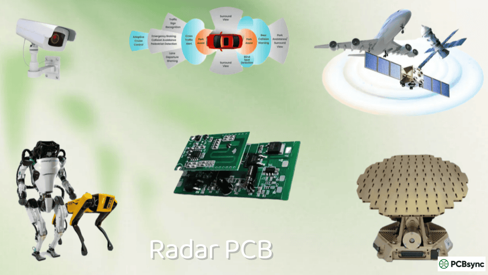
Radar and Electronic Warfare: Phased array radar systems can contain thousands of transmit/receive modules, each built around high-frequency aerospace PCBs using specialized RF laminates like Rogers 4003C or PTFE materials. Electronic warfare systems require even more demanding performance, processing wideband signals while generating jamming waveforms across multiple frequency bands simultaneously.
Weapons Guidance Systems: Perhaps no application demands more from military PCBs than weapons guidance. These boards experience extreme G-forces during launch and maneuvering while performing real-time navigation and targeting calculations. The combination of high reliability requirements and harsh operating environment makes guidance system PCBs among the most challenging to design and manufacture.
Unmanned Systems: UAVs and autonomous ground vehicles rely extensively on military-grade electronics for navigation, communication, and mission systems. These platforms often operate for extended periods without maintenance, requiring boards that can handle thermal cycling from day/night temperature swings and vibration from propulsion systems.
Aerospace and Space Applications
Commercial and Military Avionics: Modern aircraft contain dozens of line-replaceable units (LRUs) controlling everything from engine performance to flight surfaces. These aerospace PCB assemblies must meet DO-254 (hardware) and DO-178C (software) certification requirements in addition to standard aerospace quality standards.
Satellite Systems: Spacecraft electronics face unique challenges including vacuum operation, radiation exposure, and extreme thermal cycling during orbital transitions between sunlight and shadow. Aerospace PCBs for space applications require radiation-hardened components, specialized conformal coatings for outgassing prevention, and designs validated for 15+ year operational life without any possibility of repair.
Launch Vehicle Electronics: Rocket avionics must survive launch vibration levels far exceeding aircraft requirements while controlling propulsion, guidance, and payload deployment. These one-time-use systems require absolute reliability—there’s no second chance if the electronics fail during launch.
Frequently Asked Questions About Military and Aerospace PCBs
What is the difference between IPC Class 3 and MIL-SPEC PCBs?
IPC Class 3 defines acceptance criteria for high-reliability electronic assemblies through the IPC organization’s standards. MIL-SPEC (such as MIL-PRF-31032) adds government-specific requirements including qualification testing, ongoing compliance verification, and DLA oversight. A military PCB must meet IPC Class 3 requirements as a baseline, but the MIL-SPEC certification adds additional testing, documentation, and process control requirements that go beyond IPC standards. Many manufacturers can produce IPC Class 3 boards, but MIL-SPEC certification requires DLA approval and ongoing compliance.
How long does it take to qualify a manufacturer for MIL-PRF-31032?
The qualification process for MIL-PRF-31032 typically takes 12-18 months from initial application to DLA approval. This includes establishing a Technical Review Board, developing and implementing a quality plan, producing qualification test vehicles, submitting samples for testing at DLA-certified laboratories, and passing an on-site audit. Once qualified, manufacturers must maintain certification through monthly sampling, annual audits, and biennial requalification testing. The investment in time and resources is significant, which is why relatively few PCB fabricators hold this certification.
Can I use commercial off-the-shelf components in military PCB assemblies?
Using COTS components in military applications is increasingly common and is sometimes encouraged to reduce costs and improve availability. However, several conditions apply. The components must be evaluated for reliability in the intended operating environment, and additional screening or qualification testing may be required. For critical applications, MIL-SPEC components remain mandatory. When COTS components are used, they typically require upscreening to military temperature ranges and documentation of their reliability characteristics. Programs like the DESC (Defense Electronics Supply Center) drawing system allow COTS components with appropriate testing and documentation.
What environmental testing is required for aerospace PCB qualification?
Aerospace PCB qualification typically requires a battery of environmental tests per MIL-STD-810 and related specifications. Common tests include thermal shock (rapid transitions between temperature extremes), temperature cycling (gradual transitions over extended periods), humidity exposure, vibration (sinusoidal and random), mechanical shock, altitude simulation, salt fog exposure for corrosion resistance, and sand/dust exposure. The specific test requirements depend on the intended application and are typically defined in the procurement specification. For space applications, additional testing for vacuum operation and radiation tolerance is required.
How do I ensure traceability for military PCB assemblies?
Full traceability for military aerospace PCB assemblies requires documentation at every stage from raw materials through finished product. This includes material certifications for laminates, copper, and surface finishes; component lot codes and date codes linked to manufacturer certificates; process documentation showing equipment used, operator identification, and process parameters; inspection records with inspector certification; test data for all in-process and final testing; and serialization of individual assemblies. Modern manufacturing execution systems (MES) can automate much of this documentation, but the requirement for paper records and long-term archive (typically 7+ years) remains. AS9102 First Article Inspection reports provide a template for comprehensive documentation.
Conclusion
Designing and manufacturing military and aerospace PCBs requires understanding both the technical requirements and the regulatory framework that governs this industry. The specifications exist for good reasons—electronic failures in defense and aerospace applications can have consequences far beyond warranty returns.
If you’re entering this market, start by building relationships with qualified suppliers who understand the requirements. The learning curve is steep, but the standards provide clear guidance once you understand the framework. Every successful military PCB project I’ve worked on started with thorough planning and ended with rigorous testing—there are no shortcuts when reliability matters this much.
The investment in proper design, qualified materials, certified manufacturing, and comprehensive testing pays off in products that perform when they’re needed most. That’s what military and aerospace PCB engineering is really about.
Key Takeaways for Aerospace PCB Success
Looking back at the projects that succeeded versus those that struggled, several patterns emerge:
Start with specifications: Read the applicable MIL-SPECs, IPC standards, and program requirements thoroughly before beginning design. Assumptions about requirements lead to costly redesigns.
Choose qualified partners: Your manufacturer’s certifications and experience matter more than their price. A lower quote from an unqualified shop will cost more in the long run through yield issues, test failures, and schedule delays.
Design for test: Build testability into your aerospace PCB from the start. Complete test coverage catches problems before they reach the field, where failures cost exponentially more to address.
Document everything: Military programs require traceability that may seem excessive. Establish documentation practices early and maintain them consistently throughout the program.
Plan for the long term: Military systems remain in service for decades. Design with obsolescence management in mind, and maintain technical data packages that will allow requalification if components become unavailable.
The military and aerospace PCB industry isn’t for everyone—the barriers to entry are high, and the consequences of failure are severe. But for engineers who embrace the challenge, it offers the opportunity to work on some of the most demanding and consequential electronic systems ever built.
Inquire: Call 0086-755-23203480, or reach out via the form below/your sales contact to discuss our design, manufacturing, and assembly capabilities.
Quote: Email your PCB files to Sales@pcbsync.com (Preferred for large files) or submit online. We will contact you promptly. Please ensure your email is correct.
Notes: For PCB fabrication, we require PCB design file in Gerber RS-274X format (most preferred), *.PCB/DDB (Protel, inform your program version) format or *.BRD (Eagle) format. For PCB assembly, we require PCB design file in above mentioned format, drilling file and BOM. Click to download BOM template To avoid file missing, please include all files into one folder and compress it into .zip or .rar format.


