Inquire: Call 0086-755-23203480, or reach out via the form below/your sales contact to discuss our design, manufacturing, and assembly capabilities.
Quote: Email your PCB files to Sales@pcbsync.com (Preferred for large files) or submit online. We will contact you promptly. Please ensure your email is correct.
Notes: For PCB fabrication, we require PCB design file in Gerber RS-274X format (most preferred), *.PCB/DDB (Protel, inform your program version) format or *.BRD (Eagle) format. For PCB assembly, we require PCB design file in above mentioned format, drilling file and BOM. Click to download BOM template To avoid file missing, please include all files into one folder and compress it into .zip or .rar format.
If you’ve spent any time designing LED products or troubleshooting thermal issues in lighting assemblies, you already know that the PCB beneath those LEDs matters more than most people realize. A well-designed lighting PCB can mean the difference between a product that lasts 50,000 hours and one that fails within months.
I’ve worked on lighting PCB projects ranging from simple indicator strips to high-power automotive headlamps, and I can tell you firsthand: thermal management is everything. This guide will walk you through what makes lighting PCBs unique, the different types available, design considerations that actually matter, and real-world applications across industries.
A lighting PCB (printed circuit board) is a specialized circuit board designed specifically for mounting and powering light-emitting diodes (LEDs). Unlike standard FR4 boards used in consumer electronics, lighting PCBs must handle the significant heat that LEDs generate during operation.
Here’s the thing most people don’t understand about LEDs: they’re efficient at converting electricity to light, but they still produce substantial heat at the junction point. That heat needs to go somewhere. If it doesn’t dissipate properly, you’ll see brightness degradation, color shift, and premature failure.
A lighting PCB typically consists of three main layers:
Circuit Layer (Copper): This provides the conductive pathways connecting LEDs and other components. Copper thickness typically ranges from 1oz to 3oz depending on current requirements.
Dielectric Layer: This insulating layer sits between the copper traces and the base material. In metal-core PCBs, this layer is critical for thermal transfer while maintaining electrical isolation.
Base Layer: This can be aluminum, copper, FR4, ceramic, or flexible materials depending on the application requirements.
The substrate material you choose directly impacts thermal conductivity, which determines how effectively heat transfers away from your LED chips. Standard FR4 has thermal conductivity around 0.3 W/mK, while aluminum substrates range from 1-8 W/mK. That’s a significant difference when you’re pushing power through high-density LED arrays.
Types of Lighting PCBs
Choosing the right lighting PCB type depends on your specific application requirements: power level, form factor, operating environment, and budget constraints. Let me break down each type based on practical experience.
Aluminum Core Lighting PCB
Aluminum-based lighting PCBs (also called metal-core PCBs or MCPCBs) are the workhorses of the LED industry. They’re cost-effective, lightweight, and provide excellent thermal dissipation for most applications.
The structure is straightforward: copper circuit layer on top, thermally conductive dielectric in the middle, and aluminum base underneath. The aluminum core acts as an integrated heat spreader, eliminating the need for separate heat sinks in many applications.
I typically recommend aluminum lighting PCBs for applications drawing 1W or more per LED, including street lights, commercial fixtures, and automotive applications. The thermal conductivity of the dielectric layer is what really matters here, typically ranging from 1W/mK for standard products up to 8W/mK for high-performance versions.
Copper Core Lighting PCB
When aluminum isn’t enough, copper-core lighting PCBs step in. Copper has roughly twice the thermal conductivity of aluminum (approximately 400 W/mK versus 205 W/mK), making it ideal for high-power LED applications where heat density is extreme.
The downside? Cost and weight. Copper PCBs are significantly heavier and more expensive than aluminum alternatives. I’ve used them in automotive headlamp assemblies and high-bay industrial fixtures where thermal performance justified the premium.
FR4 Lighting PCB
Standard FR4 glass-epoxy boards work fine for low-power LED applications where thermal management isn’t critical. Think indicator lights, backlighting in displays, or decorative lighting with low LED density.
The key limitation is thermal conductivity: FR4 sits around 0.3-0.5 W/mK, which means heat doesn’t transfer through the board effectively. For low-power applications (0.25W LEDs or less), this is acceptable. For anything higher, you’ll need to add thermal vias, copper pours, or external heat sinking.
Flexible Lighting PCB
Flexible lighting PCBs use polyimide (PI) or PET substrates that can bend and conform to curved surfaces. LED strip lights are the most common application, but I’ve also used them in automotive interior lighting and wearable applications.
One important note: flexible lighting PCBs generally have poorer thermal dissipation than rigid alternatives. The thin substrate and lack of metal core limits heat spreading capability. This is fine for low-power applications, but high-density LED strips often require aluminum channels as secondary heat sinks.
Ceramic Lighting PCB
Ceramic substrates like aluminum nitride (AlN) or aluminum oxide (Al₂O₃) offer exceptional thermal performance combined with excellent electrical insulation. AlN ceramic can achieve thermal conductivity up to 285 W/mK.
The trade-off is cost and manufacturability. Ceramic lighting PCBs are significantly more expensive and require specialized processing. I’ve only used them in high-reliability applications like UV curing systems and medical surgical lighting where performance and reliability justify the premium.
Lighting PCB Materials Comparison
Understanding material properties helps you make informed decisions. Here’s a practical comparison:
Material
Thermal Conductivity (W/mK)
Relative Cost
Weight
Best Applications
Aluminum Core
1-8
Low-Medium
Light
Street lights, commercial fixtures, automotive
Copper Core
380-400
High
Heavy
High-power headlamps, industrial lighting
FR4
0.3-0.5
Low
Light
Indicators, low-power backlighting
Flexible (PI)
0.2-0.4
Medium
Very Light
LED strips, curved surfaces, wearables
Ceramic (AlN)
170-285
Very High
Medium
Medical, UV, high-reliability applications
Ceramic (Al₂O₃)
24-28
High
Medium
High-temperature environments
The dielectric layer thermal conductivity varies significantly between products:
Dielectric Type
Thermal Conductivity (W/mK)
Typical Thickness
Notes
Standard Prepreg
0.8-1.5
75-150μm
Cost-effective, most applications
Enhanced Ceramic-Filled
2.0-3.0
75-100μm
Better thermal performance
High-Performance
5.0-8.0
50-100μm
Premium applications
Lighting PCB Design Considerations
Getting the design right matters more than choosing expensive materials. Here are the factors that actually impact real-world performance.
Thermal Management Strategy
Heat kills LEDs. Junction temperature directly affects light output, color stability, and lifespan. The rule of thumb I follow: every 10°C reduction in junction temperature can increase LED lifetime by approximately 10,000 hours.
Effective thermal management in lighting PCB design includes:
Adequate copper area: Large copper pours under and around LED footprints improve heat spreading. I typically use 2oz or 3oz copper for high-power applications.
Thermal vias: Plated through-holes beneath LED thermal pads transfer heat to bottom layers or directly to heat sinks. Via diameter of 0.3-0.5mm with 1.2mm pitch works well for most applications.
Proper dielectric selection: Thinner dielectric layers reduce thermal resistance. A 75μm dielectric transfers heat more effectively than 150μm, but you need to balance this against voltage isolation requirements.
Heat sink interface: The connection between your lighting PCB and external heat sink matters. Thermal interface materials (TIMs) fill air gaps and improve thermal transfer.
Current Regulation and Power Design
LEDs are current-driven devices. Inconsistent current means inconsistent brightness and accelerated degradation. Your lighting PCB design should account for:
Trace width: Calculate copper trace width based on current requirements. For a 1A current on 1oz copper, you’ll need approximately 0.5-1mm trace width minimum. Use online calculators or IPC-2221 standards for precise values.
Current limiting: Either integrate current-limiting resistors or design for constant-current driver ICs. For simple strips, resistors work fine. For high-power applications, dedicated driver circuits provide better efficiency and protection.
Voltage drop: Long LED strips suffer from voltage drop along the trace length. You can mitigate this by using heavier copper, adding parallel power traces, or injecting power at multiple points.
LED Spacing and Light Distribution
Proper LED spacing affects both thermal performance and optical quality:
Thermal spacing: LEDs need enough separation that heat from one doesn’t significantly impact neighbors. Minimum spacing depends on power level, but 15-20mm is typical for 1W LEDs on aluminum substrates.
Optical uniformity: For even light distribution, LED spacing relates to beam angle and distance to diffuser. Tighter spacing gives more uniform output but increases thermal density.
Standard configurations: Common spacings include 16.7mm for 60 LEDs/meter strips and 8.3mm for 120 LEDs/meter high-density strips.
PCB Layout Best Practices
From my experience, these layout details prevent common problems:
Polarity markings: Clear cathode/anode indicators prevent assembly errors. Use silk screen legends and asymmetric pad shapes.
Thermal pad design: LED thermal pads should connect to large copper areas. Don’t isolate them with narrow necks that restrict heat flow.
Fiducial marks: Include fiducials for automated pick-and-place assembly. Two corner fiducials minimum, three is better.
Panelization: Design for efficient panel utilization. Include break-tabs or V-scores for easy depaneling without damaging LEDs.
EMI and Noise Considerations
While not as critical as in RF applications, electromagnetic interference can affect LED driver performance:
Signal routing: Keep high-frequency switching signals from LED drivers away from sensitive circuits.
Decoupling capacitors: Place ceramic capacitors close to driver ICs to filter high-frequency noise.
Lighting PCB Applications by Industry
LED lighting PCBs have penetrated virtually every industry. Here’s how requirements differ across applications.
Automotive Lighting PCB
Automotive applications present unique challenges: extreme temperature ranges (-40°C to +125°C), vibration, humidity, and strict reliability requirements.
Headlamps: High-power LED headlamps typically use copper-core or premium aluminum lighting PCBs with enhanced thermal management. Junction temperature control is critical for maintaining consistent color temperature and light output.
Tail lights and indicators: These applications use lower power LEDs but still require automotive-grade materials and construction to meet vibration and temperature cycling requirements.
Interior lighting: Flexible and rigid-flex lighting PCBs are common for dashboard backlighting, ambient lighting, and display illumination.
Street and Industrial Lighting PCB
Street lights and high-bay industrial fixtures push thermal management to the limit:
Power levels: Street lights commonly range from 50W to 200W+ requiring substantial heat dissipation.
Environmental exposure: Outdoor fixtures face temperature cycling, humidity, UV exposure, and occasional physical impact.
I’ve seen too many street light failures caused by inadequate thermal design. The lesson: don’t underestimate accumulated heat in enclosed fixtures.
Medical Lighting PCB
Medical applications demand precision and reliability:
Surgical lighting: Operating room lights require high CRI (color rendering index), consistent color temperature, and zero tolerance for failure during procedures.
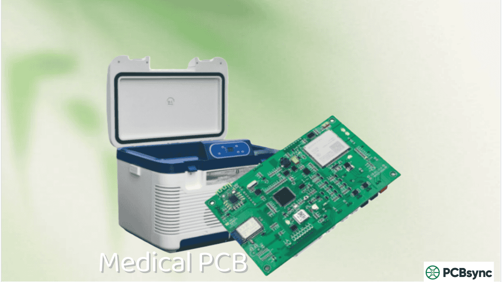
Diagnostic equipment: Endoscopes, examination lights, and dental curing lights use specialized lighting PCBs often with ceramic substrates for reliability.
Sterilization compatibility: Some medical applications require lighting PCBs that can withstand repeated sterilization cycles.
Consumer Electronics Lighting PCB
Consumer applications prioritize cost-effectiveness and form factor:
Display backlighting: Laptops, TVs, and monitors use edge-lit or direct-lit LED backlighting with tight thickness constraints.
Smartphone flash: Compact high-power LED modules require efficient thermal dissipation in minimal space.
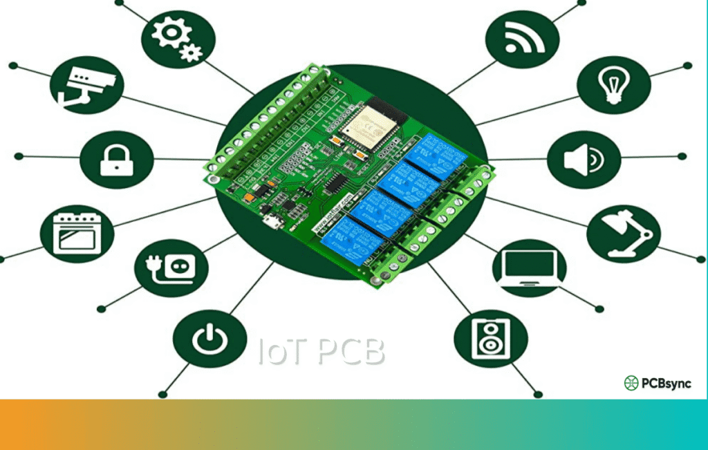
Smart home devices: LED indicators and notification lights in IoT devices use low-power lighting PCBs.
Horticultural Lighting PCB
Plant growth applications have unique spectral requirements:
Spectrum control: Grow lights use specific red and blue wavelengths optimized for plant photosynthesis.
High intensity: Commercial growing operations use high-power fixtures requiring robust thermal management.
Long operating hours: 12-18 hour daily operation for months at a time demands reliable lighting PCB design.
Understanding the manufacturing process helps you specify requirements correctly and communicate effectively with suppliers. Here’s what happens when your lighting PCB design goes into production.
Material Preparation
The process begins with raw materials: copper-clad laminates for the circuit layer and base substrates (aluminum, copper, or FR4). For metal-core lighting PCBs, the dielectric layer comes pre-bonded to the metal base from laminate suppliers.
Quality manufacturers verify incoming material specifications including:
Dielectric thermal conductivity testing
Copper purity and thickness verification
Base metal flatness and surface condition
Material certificates and lot traceability
Circuit Imaging and Etching
The copper circuit pattern is created through photolithographic imaging:
Photoresist application to copper surface
UV exposure through artwork film or direct laser imaging
Developing to remove unexposed resist
Chemical etching to remove unwanted copper
Resist stripping to reveal final circuit pattern
For lighting PCBs with heavy copper (2oz+), the etching process requires careful control to maintain trace width accuracy. Undercutting can narrow traces below design specifications.
Drilling and Routing
CNC drilling creates component holes and thermal vias. For lighting PCBs, thermal via arrays under LED pads require precise registration to maximize thermal transfer.
Typical thermal via specifications:
Diameter: 0.3-0.5mm
Pitch: 1.0-1.5mm
Plating: 25μm minimum copper
Routing defines the board outline and any internal cutouts. V-scoring or tab routing enables panelization for efficient assembly.
Surface Finish
Surface finish protects exposed copper and affects solderability. Common options for lighting PCBs include:
For LED lighting applications, I typically specify HASL or ENIG. OSP works for cost-sensitive applications but limits rework options.
Solder Mask Application
Solder mask protects circuits from oxidation and prevents solder bridges during assembly. For lighting PCBs, solder mask color affects light reflectivity:
White solder mask: Maximum light reflection, common for LED strips and fixtures
Black solder mask: Minimum reflection, used when stray light is problematic
Green solder mask: Standard, good visibility for inspection
White solder mask is almost universal for lighting PCB applications because it improves fixture efficiency by reflecting light that would otherwise be absorbed by the board.
Quality Testing
Reputable manufacturers test lighting PCBs before shipment:
Electrical testing: Continuity and isolation verification
Thermal testing: Dielectric breakdown and thermal resistance
Request thermal conductivity certificates for metal-core lighting PCBs. The dielectric thermal performance is critical and should be verified.
Lighting PCB Assembly Considerations
Getting LEDs onto your lighting PCB requires attention to process details that differ from standard SMT assembly.
Reflow Soldering Profile
LED components have temperature limits that constrain reflow profiles. Typical LED maximum temperatures are 260°C for 10 seconds or less. Ceramic LEDs tolerate higher temperatures than plastic-packaged parts.
Standard reflow profile considerations:
Preheat ramp: 1-3°C/second
Soak zone: 150-200°C for 60-120 seconds
Peak temperature: 245-260°C
Time above liquidus: 60-90 seconds maximum
Cooling ramp: 4-6°C/second maximum
Metal-core lighting PCBs have higher thermal mass than FR4, which affects reflow profile optimization. The aluminum base acts as a heat sink during reflow, potentially causing insufficient solder melting if the profile isn’t adjusted.
LED Handling and ESD Protection
LEDs are ESD-sensitive components. Proper handling procedures include:
Grounded workstations and personnel
ESD-safe packaging and transport
Humidity control to prevent static buildup
Verification of ESD protection at each handling step
LED bins (brightness and color sorting) should be tracked through assembly to maintain consistency within fixtures.
Thermal Interface Application
For lighting PCBs that mount to heat sinks, thermal interface material (TIM) application is critical:
Thermal grease: Applied in thin layers (25-75μm), requires controlled thickness for optimal performance. Too thick increases thermal resistance; too thin causes air gaps.
Thermal pads: Pre-cut to shape, consistent thickness, easier application but generally higher thermal resistance than grease.
Phase change materials: Solid at room temperature, soften under operating heat to conform to surfaces. Good compromise between grease performance and pad convenience.
These tools and references have proven valuable in my lighting PCB projects:
Design Software
KiCad (Free): Open-source PCB design software suitable for lighting PCB projects. Good community support and extensive component libraries. Download: https://www.kicad.org/
Thermal Via Calculator: Useful for estimating thermal via array performance in lighting PCB applications.
LED Manufacturer Resources
Major LED manufacturers provide detailed thermal design guidance:
Cree/Wolfspeed: LED application notes covering thermal management.
Osram/ams-OSRAM: Technical documentation for automotive and general lighting.
Lumileds: Thermal design guides for high-power LED applications.
Samsung LED: Reference designs and thermal simulation data.
Frequently Asked Questions About Lighting PCBs
What is the best material for a lighting PCB?
The best material depends on your application. For most LED lighting applications drawing more than 1W total power, aluminum-core PCBs offer the best balance of thermal performance, weight, and cost. Copper-core PCBs are better for high-power applications like automotive headlamps where thermal demands are extreme. FR4 works fine for low-power indicators and decorative lighting where heat isn’t a significant concern.
How does thermal conductivity affect lighting PCB performance?
Thermal conductivity directly determines how quickly heat transfers from LED junctions through the PCB to ambient air or heat sinks. Higher thermal conductivity means lower junction temperatures, which translates to brighter output, more stable color, and longer LED lifespan. The dielectric layer thermal conductivity typically ranges from 1-8 W/mK and is often the thermal bottleneck in lighting PCB designs.
Can I use a standard FR4 PCB for LED lighting?
Yes, but with limitations. FR4 works for low-power applications like indicator LEDs, keyboard backlighting, or decorative lighting with widely spaced LEDs. For applications with LED power above 0.5W or high LED density, the poor thermal conductivity of FR4 (0.3-0.5 W/mK) will cause excessive junction temperatures. You can partially compensate by adding thermal vias and copper pours, but metal-core PCBs are the better choice for most lighting applications.
What copper thickness should I use for lighting PCBs?
Copper thickness depends on current requirements. For typical LED strips with currents under 500mA, 1oz (35μm) copper is adequate. For high-power applications drawing 1A or more, use 2oz (70μm) or 3oz (105μm) copper. Heavier copper also improves heat spreading, which benefits thermal performance beyond just current capacity. Calculate trace width using IPC-2221 standards or online calculators based on your specific current and acceptable temperature rise.
How long do lighting PCBs last?
Properly designed lighting PCBs can support LED operation for 50,000+ hours. The PCB itself rarely fails; it’s the LEDs and driver components that typically limit system life. The key factor is keeping junction temperatures low through effective thermal design. Poorly designed lighting PCBs that allow excessive LED temperatures can reduce system life to 10,000 hours or less. Environmental factors like humidity, temperature cycling, and contamination also affect longevity.
Final Thoughts on Lighting PCB Design
Successful lighting PCB design comes down to respecting the thermal challenge. LEDs are remarkably efficient, but they’re not magic: excess heat needs somewhere to go. Choose your substrate material based on realistic thermal requirements, not just initial cost. Design adequate thermal paths from LED junctions to ambient. And don’t forget that the connection between your lighting PCB and heat sinks matters just as much as the board itself.
The lighting industry continues evolving toward higher power densities and more demanding applications. The fundamentals covered here will serve you well, but always validate your designs with thermal simulation or physical testing before committing to production volumes.
If you’re sourcing lighting PCBs, look for manufacturers with demonstrated experience in your application area. Request thermal performance data for their dielectric materials, and don’t hesitate to ask for reference designs or application notes. Good suppliers want to help you succeed because successful products mean repeat business.
The market for LED lighting continues expanding, and with it, demand for well-designed lighting PCBs. Whether you’re working on next-generation automotive systems, smart city infrastructure, or innovative consumer products, the principles in this guide will help you build lighting solutions that perform reliably for years to come.
Inquire: Call 0086-755-23203480, or reach out via the form below/your sales contact to discuss our design, manufacturing, and assembly capabilities.
Quote: Email your PCB files to Sales@pcbsync.com (Preferred for large files) or submit online. We will contact you promptly. Please ensure your email is correct.
Notes: For PCB fabrication, we require PCB design file in Gerber RS-274X format (most preferred), *.PCB/DDB (Protel, inform your program version) format or *.BRD (Eagle) format. For PCB assembly, we require PCB design file in above mentioned format, drilling file and BOM. Click to download BOM template To avoid file missing, please include all files into one folder and compress it into .zip or .rar format.


